Mellanox Technologies MIS5300 Hardware Installation Manual
- Categorie
- Șasiu echipament de rețea
- Tip
- Hardware Installation Manual
Acest manual este potrivit și pentru

www.mellanox.com
324-Port InfiniBand QDR SwitchX®
Switch Platform Hardware Installation Guide
PN:MIS5300
Rev 1.6

Document Number: 3304
Mellanox Technologies
2

InfiniBand Switch Platform Hardware User Manual
Mellanox Technologies
3
Table of Contents
List of Tables . . . . . . . . . . . . . . . . . . . . . . . . . . . . . . . . . . . . . . . . . . . . . . . . . . . . . . 5
List of Figures . . . . . . . . . . . . . . . . . . . . . . . . . . . . . . . . . . . . . . . . . . . . . . . . . . . . . 6
Revision History . . . . . . . . . . . . . . . . . . . . . . . . . . . . . . . . . . . . . . . . . . . . . . . . . . . 8
About this Manual . . . . . . . . . . . . . . . . . . . . . . . . . . . . . . . . . . . . . . . . . . . . . . . . . . 8
Chapter 1 Installation. . . . . . . . . . . . . . . . . . . . . . . . . . . . . . . . . . . . . . . . . . . . . . 10
1.1 Installation Safety Warnings . . . . . . . . . . . . . . . . . . . . . . . . . . . . . . . . . . 10
1.2 Environmental and Safety Recommendations . . . . . . . . . . . . . . . . . . . . 14
1.3 Chassis Package Contents . . . . . . . . . . . . . . . . . . . . . . . . . . . . . . . . . . . 15
1.4 Leaf Package Contents. . . . . . . . . . . . . . . . . . . . . . . . . . . . . . . . . . . . . . 16
1.5 Management Package Contents. . . . . . . . . . . . . . . . . . . . . . . . . . . . . . . 16
1.6 Physical Installation. . . . . . . . . . . . . . . . . . . . . . . . . . . . . . . . . . . . . . . . . 16
1.6.1 Starting with the Rack . . . . . . . . . . . . . . . . . . . . . . . . . . . . . . . . . . . . . . . 17
1.6.2 ESD Connection. . . . . . . . . . . . . . . . . . . . . . . . . . . . . . . . . . . . . . . . . . . . 17
1.6.3 Installation Procedure . . . . . . . . . . . . . . . . . . . . . . . . . . . . . . . . . . . . . . . 18
1.6.4 Installing the Cable Holder. . . . . . . . . . . . . . . . . . . . . . . . . . . . . . . . . . . . 37
1.6.5 Ground Connections. . . . . . . . . . . . . . . . . . . . . . . . . . . . . . . . . . . . . . . . 38
1.7 Power Connections . . . . . . . . . . . . . . . . . . . . . . . . . . . . . . . . . . . . . . . . . 39
1.7.1 Powering Up the Switch Platform. . . . . . . . . . . . . . . . . . . . . . . . . . . . . . . 40
1.8 InfiniBand QSFP Cable Installation. . . . . . . . . . . . . . . . . . . . . . . . . . . . . 41
1.8.1 Supported Approved Cables . . . . . . . . . . . . . . . . . . . . . . . . . . . . . . . . . . 42
1.8.2 Cable Power Classes. . . . . . . . . . . . . . . . . . .
. . . . . . . . . . . . . . . . . . . . . 42
1.9 Hot Swap Insertion and Extraction . . . . . . . . . . . . . . . . . . . . . . . . . . . . . 42
1.9.1 Power Supply Units . . . . . . . . . . . . . . . . . . . . . . . . . . . . . . . . . . . . . . . . . 42
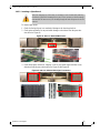
1.9.2 Leaf Boards . . . . . . . . . . . . . . . . . . . . . . . . . . . . . . . . . . . . . . . . . . . . . . . 44
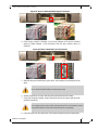
1.9.3 Spine Boards . . . . . . . . . . . . . . . . . . . . . . . . . . . . . . . . . . . . . . . . . . . . . . 47
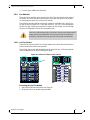
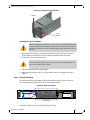
1.9.4 Fan Modules . . . . . . . . . . . . . . . . . . . . . . . . . . . . . . . . . . . . . . . . . . . . . . 52
1.9.5 Management Module . . . . . . . . . . . . . . . . . . . . . . . . . . . . . . . . . . . . . . . . 54
1.9.6 Switch Shut-Down Procedures . . . . . . . . . . . . . . . . . . . . . . . . . . . . . . . . 56
Chapter 2 Interfaces. . . . . . . . . . . . . . . . . . . . . . . . . . . . . . . . . . . . . . . . . . . . . . . 58
2.1 LED Status Indicators . . . . . . . . . . . . . . . . . . . . . . . . . . . . . . . . . . . . . . . 58
2.1.1 Power Supply Unit LEDs . . . . . . . . . . . . . . . . . . . . . . . . . . . . . . . . . . . . . 58
2.1.2 Leaf Board LED Indicators. . . . . . . . . . . . . . . . . . . . . . . . . . . . . . . . . . . . 60
2.1.3 Spine Board LED Indicators. . . . . . . . . . . . . .
. . . . . . . . . . . . . . . . . . . . . 61
2.1.4 Spine Side Panel Display LED Indicators . . . .
. . . . . . . . . . . . . . . . . . . . 62
2.1.5 Management Module LED Indicators. .
. . . . . . . . . . . . . . . . . . . . . . . . . . 63
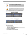
2.1.6 Port Connector Interfaces . . . . . . . . . . . . . . . . . . . . . . . . . . . . . . . . . . . . 65
2.2 Air Flow . . . . . . . . . . . . . . . . . . . . . . . . . . . . . . . . . . . . . . . . . . . . . . . . . . 66
2.3 QSFP Cable Power Budget Classification. . . . . . . . . . . . . . . . . . . . . . . . 66
2.4 Management Module Interfaces . . . . . . . . . . . . . . . . . . . . . . . . . . . . . . . 66
2.4.1 I2C . . . . . . . . . . . . . . . . . . . . . . . . . . . . . . . . . . . . . . . . . . . . . . . . . . . . . . 66
2.4.2 CONSOLE . . . . . . . . . . . . . . . . . . . . . . . . . . . . . . . . . . . . . . . . . . . . . . . . 66
2.4.3 MGT– Management. . . . . . . . . . . . . . . . . . . . . . . . . . . . . . . . . . . . . . . . . 66
2.4.4 USB . . . . . . . . . . . . . . . . . . . . . . . . . . . . . . . . . . . . . . . . . . . . . . . . . . . . . 67

InfiniBand Switch Platform Hardware User Manual
Mellanox Technologies
4
2.4.5 Reset – RST. . . . . . . . . . . . . . . . . . . . . . . . . . . . . . . . . . . . . . . . . . . . . . . 67
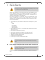
Chapter 3 Chassis Power Up. . . . . . . . . . . . . . . . . . . . . . . . . . . . . . . . . . . . . . . . 68
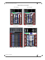
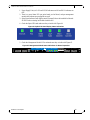
3.1 Power Supply and Spine Board Indicator Status at Power ON. . . . . . . . 68
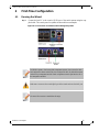
Chapter 4 First-Time Configuration . . . . . . . . . . . . . . . . . . . . . . . . . . . . . . . . . . 70
4.1 Running the Wizard. . . . . . . . . . . . . . . . . . . . . . . . . . . . . . . . . . . . . . . . . 70
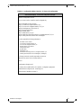
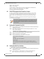
4.2 Re-Running the Wizard. . . . . . . . . . . . . . . . . . . . . . . . . . . . . . . . . . . . . . 75
4.3 Downloading FabricIT Software and Documents . . . . . . . . . . . . . . . . . . 75
4.4 Installing Licenses. . . . . . . . . . . . . . . . . . . . . . . . . . . . . . . . . . . . . . . . . . 76
4.5 Getting and Inserting the License Key. . . . . . . . . . . . . . . . . . . . . . . . . . . 76
4.6 FabricIT Management and Inspection License . . . . . . . . . . . . . . . . . . . . 78
4.7 Starting the Command Line (CLI) . . . . . . . . . . . . . . . . . . . . . . . . . . . . . . 78
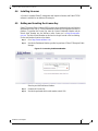
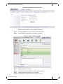
4.8 Starting the Web User Interface . . . . . . . . . . . . . . . . . . . . . . . . . . . . . . . 78
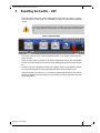
Chapter 5 Resetting the Switch – RST . . . . . . . . . . . . . . . . . . . . . . . . . . . . . . . . 81
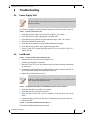
Chapter 6 Troubleshooting . . . . . . . . . . . . . . . . . . . . . . . . . . . . . . . . . . . . . . . . . 82
6.1 Power Supply Unit. . . . . . . . . . . . . . . . . . . . . . . . . . . . . . . . . . . . . . . . . . 82
6.2 Leaf Board. . . . . . . . . . . . . . . . . . . . . . . . . . . . . . . . . . . . . . . . . . . . . . . . 82
6.3 Management Module. . . . . . . . . . . . . . . . . . . . . . . . . . . . . . . . . . . . . . . . 83
6.4 Spine Board. . . . . . . . . . . . . . . . . . . . . . . . . . . . . . . . . . . . . . . . . . . . . . . 84
6.5 FabricIT Software . . . . . . . . . . . . . . . . . . . . . . . . . . . . . . . . . . . . . . . . . . 84
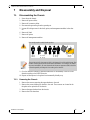
Chapter 7 Disassembly and Disposal. . . . . . . . . . . . . . . . . . . . . . . . . . . . . . . . . 85
7.1 Disassembling the Chassis . . . . . . . . . . . . . . . . . . . . . . . . . . . . . . . . . . . 85
7.1.1 Removing the Chassis. . . . . . . . . . . . . . . . . . . . . . . . . . . . . . . . . . . . . . . 85
7.1.2 Removing the Bottom Shelf . . . . . . . . . . . . . . . . . . . . . . . . . . . . . . . . . . . 86
7.2 Disposal. . . . . . . . . . . . . . . . . . . . . . . . . . . . . . . . . . . . . . . . . . . . . . . . . . 86
Appendix A Installation Safety Warnings . . . . . . . . . . . . . . . . . . . . . . . . . . . . . 87
A.1 Installation Safety Warnings (English) . . . . . . . . . . . . . . . . . . . . . . . . 87
A.2 安裝安全性警告 (Chinese) . . . . . . . . . . . . . . . . . . . . . . . . . . . . . . . . . 91
A.3 Avertissements de sécurité pour l'installation (French) . . . . . . . . . . . 96
A.4 Installation Sicherheitshinweise(German). . . . . . . . . . . . . . . . . . . . . 101
A.5 Advertencias de seguridad de instalación (Spanish) . . . . . . . . . . . . 105
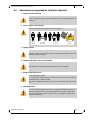
A.6 Предупреждения по технике безопасности при установке (Russian) 109
A.7 Avertismente privind siguranţa la instalare (Romanian) . . . . . . . . . . 113
A.8 Sigurnosna upozorenja za instaliranje (Croatian). . . . . . . . . . . . . . . 118

InfiniBand Switch Platform Hardware User Manual
Mellanox Technologies
5
List of Tables
Table 1: Revision History of this User’s Manual. . . . . . . . . . . . . . . . . . . . . . . . . . . . . . . . . 8
Table 2: Reference Documents and Websites. . . . . . . . . . . . . . . . . . . . . . . . . . . . . . . . . . 9
Table 3: Leaf Status LED. . . . . . . . . . . . . . . . . . . . . . . . . . . . . . . . . . . . . . . . . . . . . . . . . 60
Table 4: Connector Physical and Logical Link Indications
. . . . . . . . . . . . . . . . . . . . . . . . 60
Table 5: Spine Status LED. . . . . . . . . . . . . . . . . . . . . . . . . . . . . . . . . . . . . . . . . . . . . . . . 61
Table 6: Spine Fan Status LED . . . . . . . . . . . . . . . . . . . . . . . . . . . . . . . . . . . . . . . . . . . . 62
Table 7: Spine to Leaf IB Link Status. . . . . . . . . . . . . . . . . . . . . . . . . . . . . . . . . . . . . . . . 62
Table 8: LEDs Display for Normal Operation. . . . . . . . . . . . . . . . . . . . . . . . . . . . . . . . . . 63
Table 9: LEDs Display for Normal Operation. . . . . . . . . . . . . . . . . . . . . . . . . . . . . . . . . . 64
Table 10: Management Module PSU LED Configurations . . . . . . . . . . . . . . . . . . . . . . . . 64
Table 11: Management Module S.Fan LED Configurations . . . . . . . . . . . . . . . . . . . . . . . 65
Table 12: Management Module L.Fan LED Configurations . . . . . . . . . . . . . . . . . . . . . . . 65
Table 13: Management Module MASTER LED Configurations . . . . . . . . . . . . . . . . . . . . 65
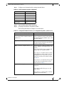
Table 14: Serial Terminal Program Configuration . . . . . . . . . . . . . . . . . . . . . . . . . . . . . . . 71
Table 15: Configuration Wizard Session - IP Configuration by DHCP. . . . . . . . . . . . . . . . 71
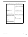
Table 16: Configuration Wizard Session - IP Zeroconf Configuration
. . . . . . . . . . . . . . . . 73
Table 17: Configuration Wizard Session - St
atic IP Configuration. . . . . . . . . . . . . . . . . . . 74

InfiniBand Switch Platform Hardware User Manual
Mellanox Technologies
6
List of Figures
Figure 1: Distance Between the Vertical Supports . . . . . . . . . . . . . . . . . . . . . . . . . . . . . 17
Figure 2: Installation Kit Parts . . . . . . . . . . . . . . . . . . . . . . . . . . . . . . . . . . . . . . . . . . . . . 20
Figure 3: Shock and Tilt Stickers . . . . . . . . . . . . . . . . . . . . . . . . . . . . . . . . . . . . . . . . . . . 21
Figure 4: Container Screws . . . . . . . . . . . . . . . . . . . . . . . . . . . . . . . . . . . . . . . . . . . . . . . 22
Figure 5: Vertical Rack Supports Dimension . . . . . . . . . . . . . . . . . . . . . . . . . . . . . . . . . . 24
Figure 6: Placement of Chassis in Rack . . . . . . . . . . . . . . . . . . . . . . . . . . . . . . . . . . . . . 24
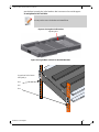
Figure 7: Adjustable Shelf Brackets . . . . . . . . . . . . . . . . . . . . . . . . . . . . . . . . . . . . . . . . 25
Figure 8: Top of Shelf Bracket . . . . . . . . . . . . . . . . . . . . . . . . . . . . . . . . . . . . . . . . . . . . . 25
Figure 9: Placing the Shelf Bracket . . . . . . . . . . . . . . . . . . . . . . . . . . . . . . . . . . . . . . . . . 26
Figure 10: Caged Nut Locations for the Shelf Brackets . . . . . . . . . . . . . . . . . . . . . . . . . . 26
Figure 11: Shelf Brackets . . . . . . . . . . . . . . . . . . . . . . . . . . . . . . . . . . . . . . . . . . . . . . . . . . 27
Figure 12: U Numbering Above Shelf . . . . . . . . . . . . . . . . . . . . . . . . . . . . . . . . . . . . . . . . . 27
Figure 13: Putting the Chassis in the Rack Using a Fork Lift . . . . . . . . . . . . . . . . . . . . . . . 28
Figure 14: Putting the Chassis in the Rack Using a Mechanical Lift . . . . . . . . . . . . . . . . . 29
Figure 15: Place the Upper Bracket Offset . . . . . . . . . . . . . . . . . . . . . . . . . . . . . . . . . . . . . 29
Figure 16: Attach the Shelf Extension . . . . . . . . . . . . . . . . . . . . . . . . . . . . . . . . . . . . . . . . 30
Figure 17: Caged Nut Placement by U Numbers . . . . . . . . . . . . . . . . . . . . . . . . . . . . . . . . 31
Figure 18: Location for the Lock-Down Bar . . . . . . . . . . . . . . . . . . . . . . . . . . . . . . . . . . . . 31
Figure 19: Fork Lift . . . . . . . . . . . . . . . . . . . . . . . . . . . . . . . . . . . . . . . . . . . . . . . . . . . . . . . 32
Figure 20: Mechanical Lift . . . . . . . . . . . . . . . . . . . . . . . . . . . . . . . . . . . . . . . . . . . . . . . . . 32
Figure 21: Face Plate Mounting Bolt Locations . . . . . . . . . . . . . . . . . . . . . . . . . . . . . . . . . 33
Figure 22: Upper Bracket Installation . . . . . . . . . . . . . . . . . . . . . . . . . . . . . . . . . . . . . . . . 33
Figure 23: Upper Brackets and Offset Location . . . . . . . . . . . . . . . . . . . . . . . . . . . . . . . . . 34
Figure 24: Offset to Upper Bracket Bolts . . . . . . . . . . . . . . . . . . . . . . . . . . . . . . . . . . . . . . 34
Figure 25: Location for the Lock-Down Bar . . . . . . . . . . . . . . . . . . . . . . . . . . . . . . . . . . . . 34
Figure 26: Lock-Down Bar . . . . . . . . . . . . . . . . . . . . . . . . . . . . . . . . . . . . . . . . . . . . . . . . . 35
Figure 27: Lock-Down Bars Bolt and Washer Order . . . . . . . . . . . . . . . . . . . . . . . . . . . . . 35
Figure 28: Spine Side with Filler Panels . . . . . . . . . . . . . . . . . . . . . . . . . . . . . . . . . . . . . . . 36
Figure 29: Cable Holder . . . . . . . . . . . . . . . . . . . . . . . . . . . . . . . . . . . . . . . . . . . . . . . . . . 37
Figure 30: Ground Connection . . . . . . . . . . . . . . . . . . . . . . . . . . . . . . . . . . . . . . . . . . . . . 39
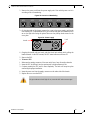
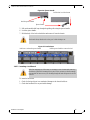
Figure 31: Multiple Power Inlets – Electric Caution Notification . . . . . . . . . . . . . . . . . . . . . 40
Figure 32: Spine Module . . . . . . . . . . . . . . . . . . . . . . . . . . . . . . . . . . . . . . . . . . . . . . . . . . 41
Figure 33: Power Cord Numbering . . . . . . . . . . . . . . . . . . . . . . . . . . . . . . . . . . . . . . . . . . . 43
Figure 34: Power Supply . . . . . . . . . . . . . . . . . . . . . . . . . . . . . . . . . . . . . . . . . . . . . . . . . . 43
Figure 35: Leaf Board Numbering . . . . . . . . . . . . . . . . . . . . . . . . . . . . . . . . . . . . . . . . . . . 44
Figure 36: Ejector Handle . . . . . . . . . . . . . . . . . . . . . . . . . . . . . . . . . . . . . . . . . . . . . . . . . . 45
Figure 37: Leaf Release . . . . . . . . . . . . . . . . . . . . . . . . . . . . . . . . . . . . . . . . . . . . . . . . . . . 45

InfiniBand Switch Platform Hardware User Manual
Mellanox Technologies
7
Figure 38: Intact vs Defected Signal Connectors . . . . . . . . . . . . . . . . . . . . . . . . . . . . . . . . 46
Figure 39: Intact vs Defected Power Pin Holders . . . . . . . . . . . . . . . . . . . . . . . . . . . . . . . . 46
Figure 40: Management Module Numbering . . . . . . . . . . . . . . . . . . . . . . . . . . . . . . . . . . . 48
Figure 41: Spine Board Extraction . . . . . . . . . . . . . . . . . . . . . . . . . . . . . . . . . . . . . . . . . . 48
Figure 42: Intact vs Defected Mechanics . . . . . . . . . . . . . . . . . . . . . . . . . . . . . . . . . . . . . . 50
Figure 43: Intact vs Defected Side Signal Connectors . . . . . . . . . . . . . . . . . . . . . . . . . . . . 50
Figure 44: Intact vs Defected Middle Signal Connectors . . . . . . . . . . . . . . . . . . . . . . . . . . 51
Figure 45: Intact vs Defected Power Pin Holders . . . . . . . . . . . . . . . . . . . . . . . . . . . . . . . . 51
Figure 46: Leaf Fan Locations on the Chassis . . . . . . . . . . . . . . . . . . . . . . . . . . . . . . . . . . 52
Figure 47: Leaf Fan Module Extraction . . . . . . . . . . . . . . . . . . . . . . . . . . . . . . . . . . . . . . . 53
Figure 48: Spine Fan Module . . . . . . . . . . . . . . . . . . . . . . . . . . . . . . . . . . . . . . . . . . . . . . 53
Figure 49: Fan Status LED on the Spine Module . . . . . . . . . . . . . . . . . . . . . . . . . . . . . . . 54
Figure 50: Management Module . . . . . . . . . . . . . . . . . . . . . . . . . . . . . . . . . . . . . . . . . . . 55
Figure 51: Intact vs Defected Signal Connectors . . . . . . . . . . . . . . . . . . . . . . . . . . . . . . . . 55
Figure 52: Intact vs Defected Power Pin Holders . . . . . . . . . . . . . . . . . . . . . . . . . . . . . . . . 56
Figure 53: Power Supply Unit Status Indications . . . . . . . . . . . . . . . . . . . . . . . . . . . . . . . 58
Figure 54: PSU Cover On and Off . . . . . . . . . . . . . . . . . . . . . . . . . . . . . . . . . . . . . . . . . 59
Figure 55: Leaf Board Led Indicators . . . . . . . . . . . . . . . . . . . . . . . . . . . . . . . . . . . . . . . . . 60
Figure 56: Spine Status LEDs . . . . . . . . . . . . . . . . . . . . . . . . . . . . . . . . . . . . . . . . . . . . . . 61
Figure 57: Spine Side Panel Display Status Indications . . . . . . . . . . . . . . . . . . . . . . . . . . 62
Figure 58: Management Module Status Indications . . . . . . . . . . . . . . . . . . . . . . . . . . . . . 63
Figure 59: Management Module LEDs . . . . . . . . . . . . . . . . . . . . . . . . . . . . . . . . . . . . . . . . 64
Figure 60: Port Numbering . . . . . . . . . . . . . . . . . . . . . . . . . . . . . . . . . . . . . . . . . . . . . . . . . 65
Figure 61: Top and Bottom Ports . . . . . . . . . . . . . . . . . . . . . . . . . . . . . . . . . . . . . . . . . . . . 65
Figure 62: Management Module Interfaces . . . . . . . . . . . . . . . . . . . . . . . . . . . . . . . . . . . . 66
Figure 63: Reset Button . . . . . . . . . . . . . . . . . . . . . . . . . . . . . . . . . . . . . . . . . . . . . . . . . . . 67
Figure 64: Spine Side Panel Display Status Indications . . . . . . . . . . . . . . . . . . . . . . . . . . 69
Figure 65: Management Module Status Indications for Normal Operation . . . . . . . . . . . . 69
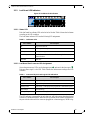
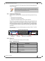
Figure 66: Console Ports for SX60xx/SX65xx Managed Systems . . . . . . . . . . . . . . . . . . . 70
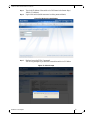
Figure 67: License Key Entitlement Number . . . . . . . . . . . . . . . . . . . . . . . . . . . . . . . . . . . 76
Figure 68: License Key Generation Form . . . . . . . . . . . . . . . . . . . . . . . . . . . . . . . . . . . . . 77
Figure 69: FabricIT Status/Licensing . . . . . . . . . . . . . . . . . . . . . . . . . . . . . . . . . . . . . . . . . 77
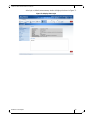
Figure 70: MLNX-OS Login Window . . . . . . . . . . . . . . . . . . . . . . . . . . . . . . . . . . . . . . . . . 79
Figure 71: EULA Prompt . . . . . . . . . . . . . . . . . . . . . . . . . . . . . . . . . . . . . . . . . . . . . . . . . . 79
Figure 72: Display After Login . . . . . . . . . . . . . . . . . . . . . . . . . . . . . . . . . . . . . . . . . . . . . . 80
Figure 73: Reset Button . . . . . . . . . . . . . . . . . . . . . . . . . . . . . . . . . . . . . . . . . . . . . . . . . . . 81
Figure 74: Mechanical Lifting Device . . . . . . . . . . . . . . . . . . . . . . . . . . . . . . . . . . . . . . . . . 86

InfiniBand Switch Platform Hardware User Manual
Mellanox Technologies
8
Revision History
About this Manual
This manual provides installation and set-up instructions for the IS5300 GT series QSFP
Chassis InfiniBand Switch Platform.
Intended Audience
This manual is intended for users and system administrators responsible for installing
and setting up the chassis platform.
The manual assumes familiarity with the InfiniBand
®
architecture specification.
Table 1 - Revision History of this User’s Manual
Revision Date Details
1.6 Feb. 2014 Rearranged document: Consolidated installation sections under
Chapter 1, “Installation,” on page 10; updated Chapter 1, “Overview,”
on page 12; and re-ordered sections).
Added:
• Figure 59, “Management Module LEDs,” on page 64
Updated:
• Section 1.4, “Power Supply Redundancy,” on page 15
• Section 1.6.3.5, “Installing the Shelf,” on page 23
• Section 1.6.4, “Installing the Cable Holder,” on page 37
• Section 1.9, “Hot Swap Insertion and Extraction,” on page 42
• Section 7.1, “Disassembling the Chassis,” on page 85
• Appendix A, “Installation Safety Warnings,” on page 87
1.5 July 2011 Changes to Resetting the Switch section
1.4 Nov. 2010
• Changes to parts list
• Minor changes to installation procedure
1.3 Oct. 2010 Added air flow direction
1.2 Oct. 2010 Added step screw in bolts from offset to upper bracket.
1.1 Aug. 2010
• Added weight lifting warning
• Added “Remove all protective plastic film from all sides and top of the
chassis.”
• Added cable power classes
1.0.1 July 2010 Added last page with barcode
1.0 July 2010 First release

InfiniBand Switch Platform Hardware User Manual
Mellanox Technologies
9
Related Documentation
The documentation set accompanying the QSFP Chassis InfiniBand Switch platform
includes the following:
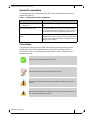
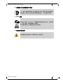
Conventions
Throughout this manual, the name IS5300 and the terms chassis and switch are used to
describe the 324 port QSFP InfiniBand chassis, unless explicitly indicated otherwise.
The following icons are used throughout this document to indicat
e information that is
important to the user.
Table 2 - Reference Documents and Websites
Document Name Description
InfiniBand Architecture Specification,
Vol. 1, Release 1.2.1
The InfiniBand Architecture Specification that is provided by
IBTA
Switch Product Release Notes For possible hardware issues see the switch support product
page.
This requires a customer support login. Look up the rele-
vant SwitchX®-based switch system/se
ries release note file.
Mellanox MLNX-OS® User Manual
for
VPI
This document contains information regarding configuring and
managing Mellanox Technologies SwitchX® switch platforms
listing all of the commands available through MLNX-OS with
explanations and examples.
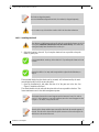
This symbol makes recommendations to the user.
This symbol indicates information that is helpful to the user.
This symbol indicates a situation that can potentially cause damage to hardware or
software.
Warning! This symbol indicates a situation that can potentially cause personal injury
and / or damage to hardware or software.

InfiniBand Switch Platform Hardware User Manual
Mellanox Technologies
10
1Installation
Installation and initialization of the chassis is a simple process requiring attention to the
normal mechanical, power, and thermal precautions for rack-mounted equipment. Your
Chassis will be shipped in two packages one with the all of the leafs (leaf package) that
are ordered and an extra management module should it be ordered, and the second pack-
age (chassis package) with all of
the rest of the parts.
The chassis requires initial configuration
to get the chassis and Fabric management up
and running through remote management. See the Installation Guide that is packed in the
box for the instructions to make the initial configuration.
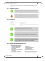
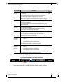
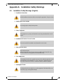
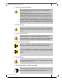
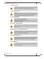
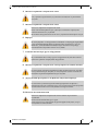
1.1 Installation Safety Warnings
These safety warnings are in English. For French, German, Spanish, Russian, and Roma-
nian see the Appendixes.
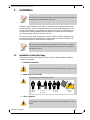
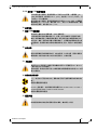
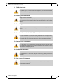
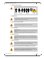
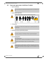
1. Installation Instructions
2. Bodily Injury Due to Weight
3. Heavy Equipment
This chassis can be installed in standard 19” racks that have depths between 65cm and
80cm between the vertical supports of the rack.
This unit is intended for installation in a Restricted Access Location. A restricted
access area can be accessed only through the use of a special tool, lock and key, or
other means of security.
Read all installation instructions before connecting the equipment to the power source.
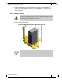
Use enough people to safely lift this product.
This equipment is very heavy and should be moved using a mechanical lift to avoid
injuries.
<40 lbs
<18 kgs
40 - 70 lbs
18 - 32 kgs
70 - 121 lbs
32 - 55 kgs
>121 lbs
>55 kgs

InfiniBand Switch Platform Hardware User Manual
Mellanox Technologies
11
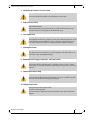
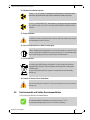
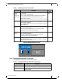
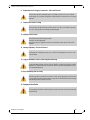
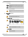
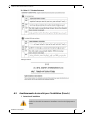
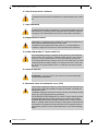
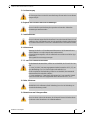
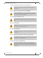
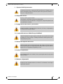
4. Installation in Restricted Access Location
5. Risk of Electric Shock!
6. Over-temperature
7. Stacking the Chassis
8. Redundant Power Supply Connection - Electrical Hazard
9. Double Pole/Neutral Fusing
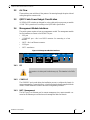
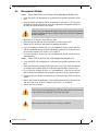
10. Multiple Power Inlets ,
This unit is intended for installation in a Restricted Access Location.
Risk of Electric Shock!
With the fan module removed power pins are accessible within the module cavity.
DO NOT insert tools or body parts into the fan module cavity.
This equipment should not be operated in an area with an ambient temperature exceed-
ing the maximum recommended: 45°C (113°F). Moreover, to guarantee proper air
flow, allow at least 8cm (3 inches) of clearance around the ventilation openings.
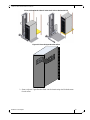
The chassis should not be stacked on any other equipment. If the chassis falls, it can
cause bodily injury and equipment damage.
This product includes a redundant power or a blank in its place. In case of a blank
power supply, do not operate the product with the blank cover removed or not securely
fastened.
This system has double pole/neutral fusing. Remove all power cords before opening
the cover of this product or touching any internal parts.
Risk of electric shock and energy hazard.
The PSUs are all independent.
Disconnect all power supplies to ensure a powered down state inside of the switch
platform.

InfiniBand Switch Platform Hardware User Manual
Mellanox Technologies
12
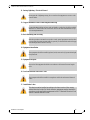
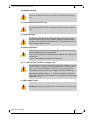
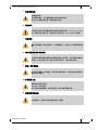
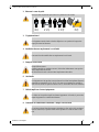
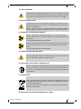
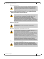
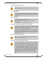
11. During Lightning - Electrical Hazard
12. Copper InfiniBand Cable Connecting/Disconnecting
13. Rack Mounting and Servicing
14. Equipment Installation
15. Equipment Disposal
16. Local and National Electrical Codes
17. Installation Codes
During periods of lightning activity, do not work on the equipment or connect or dis-
connect cables.
Copper InfiniBand cables are heavy and not flexible, as such they should be carefully
attached to or detached from the connectors. Refer to the cable manufacturer for spe-
cial warnings/instructions.
When this product is mounted or serviced in a rack, special precautions must be taken
to ensure that the system remains stable. In general you should fill the rack with equip-
ment starting from the bottom to the top.
This equipment should be installed, replaced, and/or serviced only by trained and qual-
ified personnel.
Disposal of this equipment should be in accordance to all national laws and regula-
tions.
This equipment should be installed in compliance with local and national electrical
codes.
This device must be installed according to the latest version of the country
national electrical codes. For North America, equipment must be installed in
accordance to the applicable requirements in the US National Electrical Code
and the Canadian Electrical Code.

InfiniBand Switch Platform Hardware User Manual
Mellanox Technologies
13
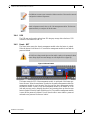
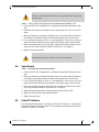
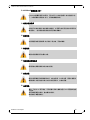
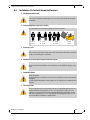
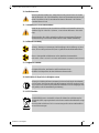
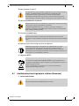
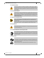
18. Battery Replacement
19. UL Listed and CSA Certified Power Supply Cord
20. High Leakage Current
21. Add GND connection information
22. Installation codes
23. Interconnection Of Units
Warning: Replace only with UL Recognized battery, certified for maximum
abnormal charging current not less than 4mA
There is a risk of explosion should the battery be replaced with a battery of an
incorrect type.
Dispose of used batteries according to the instructions.
For North American power connection, select a power supply cord that is UL Listed
and CSA Certified, 3 - conductor, [16 AWG], terminated with a molded plug rated at
125 V, [13 A], with a minimum length of 1.5m [six feet] but no longer than 4.5m.
For European connection, select a power supply cord that is internationally
harmonized and marked “<HAR>”, 3 - conductor, minimum 1.0 mm
2
wire,
rated at 300 V, with a PVC insulated jacket. The cord must have a molded plug
rated at 250 V, 10 A.
Warning: High leakage current; Earth connection essential before connecting supply.
Before connecting this device to the power line, the protective earth terminal screws of
this device must be connected to the protective earth in the building installation.
(GND Connection Information):
The building installation shall provide a means for a connection to protective earth;
and the equipment shall be permanently connected to that by a service person.
A SERVICE PERSON shall check whether or not the socket - outlet from which the
equipment is to be powered provides a connection to the building protective earth. If
not, the SERVICE PERSON shall arrange for the installation of a PROTECTIVE
EARTHING CONDUCTOR from the separate protective earthing terminal to the pro-
tective earth wire in the building. The equipment shall be installed in area where equi-
potential bonding exists ((such as a telecommunication centre or a dedicated computer
room).
This device must be installed according to the latest version of the country national
electrical codes. For North America, equipment must be installed in accordance to the
applicable requirements in the US National Electrical Code and the Canadian Electri-
cal Code.
Cables for connecting to the unit RS232 and Ethernet Interfaces must be UL
certified type DP-1 or DP-2. (Note- when residing in non LPS circuit)
Overcurrent Protection: A readily accessible Listed branch circuit overcurrent
protective device rated 20 A must be incorporated in the building wiring.

InfiniBand Switch Platform Hardware User Manual
Mellanox Technologies
14
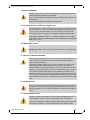
24. Hazardous Radiation Exposure
25. Proper Enclosure
26. Do Not Use the Switch as a Shelf or Work Space
27. WEEE Directive
28. Country of Norway Power Restrictions
1.2 Environmental and Safety Recommendations
The following are Mellanox recommendations.
Caution – Use of controls or adjustment or performance of procedures other
than those specified herein may result in hazardous radiation exposure.
CLASS 1 LASER PRODUCT and reference to the most recent laser standards
IEC 60 825-1:1993 + A1:1997 + A2:2001 and EN 60825-1:1994+A1:1996+
A2:2001
A suitable electrical, mechanical and fire enclosure shall be provided by the end prod-
uct manufacturer and or the end user.
Caution: Slide/rail mounted equipment is not to be used as a shelf or a work space. The
rails are not intended for sliding the unit away from the rack. It is for permanent instal-
lation at final resting place only, not used for service and maintenance
According to the WEEE Directive 2002/96/EC, all waste electrical and electronic
equipment (EEE) should be collected separately and not disposed of with regular
household waste.
Dispose of this product and all of its parts in a responsible and environmentally
friendly way.
This unit is intended for connection to a TN power system and an IT power system of
Norway only.
Recommended ambient temperature in the System room is 20
o
± 5
o
C.
Recommended humidity range is 40% ± 15% without condensing.

InfiniBand Switch Platform Hardware User Manual
Mellanox Technologies
15
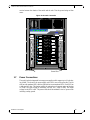
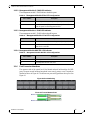
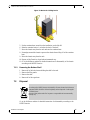
1.3 Chassis Package Contents
The package includes:
• 1 chassis with the following modules inst
alled:
•9 spines
• 1 management module
•4 fans
• 6 PSUs
• 1 installation guide
• 1 box containing various other parts
• 1 installation kit box
• 1 box containing 6 power cords 250v 15a 2.0M, C14 to C13, USA UL Standard
• 1 cable management kit
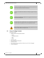
It is highly recommended that the installation sites be as isolated as possible from all
sources of radio transmissions and electrical interference.
It is highly recommended that the installation site building be equipped with a light-
ning rod.
It is highly recommended that the installation site be equipped with smoke detectors
and a fire alarm warning system.
The system requires a KVA rated UPS system. It is recommended that a UPS system
be installed to protect the equipment in the event of unexpected power failure.
Make sure that the outlets and circuits will not be overloaded. Spread out the load over
at least two or three circuits or use a 3 phase circuit.

InfiniBand Switch Platform Hardware User Manual
Mellanox Technologies
16
Before you install your new IS5300 series chassis, unpack the system and check to make
sure that all the parts have been sent, check this against the parts list. Check the parts for
visible damage that may have occurred during shipping.
1.4 Leaf Package Contents
The leafs are ordered by the customer and are shipped 4 to a box. The customer will
receive as many boxes as needed to fill the order.
1.5 Management Package Contents
When a second management module is ordered the package includes:
• 1 management module ordered by the customer
•
1 RJ45 to DB9 harness
1.6 Physical Installation
The switch platform uses 18U of rack space in a standard 19” rack, 16U for the chassis
and 2U for the shelf. The switch ships from the factory with mounting holes on the spine
side. There are upper brackets to connect the leaf side to the rack near the top of the chas-
sis, and there are two lock-down bars to secure the
chassis to the shelf. The weight of the
switch is supported from underneath the unit by the shelf.
This chassis can be installed in standard 19” racks tha
t have between 65cm and 80cm
between the vertical supports of the rack. Make sure that a fully populated rack including
cables will have sufficient air flow for cooling.
If anything is damaged or missing, contact your customer representative immediately.
The rack mounting holes conform to the EIA-310 standard for 19-inch racks. Guaran-
tee proper ventilation, by leaving 8cm (3”) of space to the front and rear of the switch.
This will ensure proper air flow through the chassis. This is crucial for maintaining
good airflow at ambient temperature. In particular, route cables such that they do not
impede the air into or out of the chassis.
Warning: This equipment is very heavy. Safety is the first concern. Make sure that
adequate manpower and proper equipment is used for transporting and moving the
chassis.
The fully loaded chassis weighs:
212.36 kg (468 LBS) full configuration
90 kg (199 LBS) empty configuration
154kg (339 LBS.) shipped configuration
Choose a rack which is able to support the mechanical and environmental characteris-
tics of a fully populated switch chassis.

InfiniBand Switch Platform Hardware User Manual
Mellanox Technologies
17
1.6.1 Starting with the Rack
Rack Recommendation
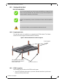
1.6.1.1 Preparing the Rack
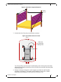
The rack may need to be modified to accommodate the IS5300 c
hassis. The distance
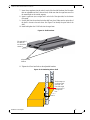
between the vertical supports must be between 65 and 80cm.
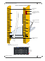
Figure 1: Distance Between the Vertical Supports
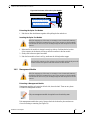
1.6.2 ESD Connection
Before starting any procedure on the IS5300 switch system:
1. Put an ESD prevention wrist strap on your wrist, and
make sure there is good contact
between your body and the strap.
Due to the space required by up to 324 connector cables Mellanox recommends a rack
that is 100 cm long and 80cm wide. This will allow for proper cable management and
enough ventilation to properly cool the chassis.
Mellanox recommends that you remove both sides of the rack to make the installation
easier.
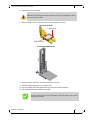
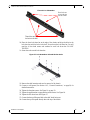
You will need a fork lift, to move and insert the chassis into the rack.
This edge of the shelf must be as
close as possible to the inside of
the door when closed.
Vertical Supports
Between 65 and 80 cm.

InfiniBand Switch Platform Hardware User Manual
Mellanox Technologies
18
2. Plug the other end of the wrist strap to a valid ground. Make sure that this is a tight
fit.
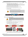
1.6.3 Installation Procedure
1.6.3.1 Requirements
You will need:
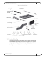
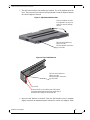
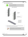
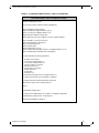
1.6.3.2 Installation and Cable Management Kit Parts
• Parts included in the installation kit:
Installing the chassis will be a lot easier if you can remove the sides of the rack.
You will need a fork lift, to move and insert the chassis into the rack.
• #2 phillips screwdriver • #3 phillips screwdriver
• a fork lift • a grounding lug
• measuring tape • ground wire of sufficient length and gauge to properly ground the
cha
ssis
The installation will be much easier with a power screwdriver.
It is recommended to use AWG6 or 4mm diameter wire for grounding purposes.
It is recommended to have at least two people for the duration of the installation proce-
dure. Use a mechanical lift to raise this chassis. If not, use enough manpower to ensure
the safety and wellbeing of all of the people involved in the installation.
- 1 shelf with brackets pre-installed - 1 shelf extension
- 1 left side upper bracket offset - 1 right side upper bracket offset
- 2 lock down bars - 2 upper bracket washers
- 8 lock washers for the upper brackets to
vertical support
- 1 nut Size M-6 for ground post
- 10 hex head bolts – 8 for the upper
brackets and 2 for the shelf extension
- 26 caged nuts 12 for the shelf and 8 for the
chassis faceplate and 6 for the filler panels

InfiniBand Switch Platform Hardware User Manual
Mellanox Technologies
19
• Parts included in the cable management installation kit:
- 26 pan head screws for the caged nuts 12
for the shelf and 8 for the chassis faceplate
and 6 for the filler panels
- 32 hex head bolts – 20 for the lock down
bars and 12 for the upper brackets to upper
bracket offsets
- 32 lock washers – 20 for the lock down
bars and 12 for the upper brackets to
upper bracket offsets
- 12 flat head screws for the upper bracket
offsets
- 2 upper brackets - 1 socket nut driver 8mm
- 1 open end ratchet wrench 10mm - 1 socket nut driver 10mm
- 1 socket wrench - 1 socket nut driver 14mm
- 2 extensions for the socket driver - 1 box wrench
- 2 flat washers for the shelf extension - 6 two hole lock washers for lock down bars
- Bottom filler panel - Top filler panel
- 1 cable management rack RH - 1 cable management rack LH
- 14 caged nuts M6 - 14 M6 bolts
- 9 cable management shelves

InfiniBand Switch Platform Hardware User Manual
Mellanox Technologies
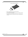
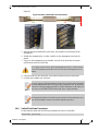
20
Figure 2: Installation Kit Parts
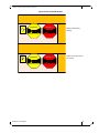
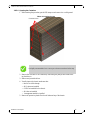
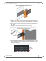
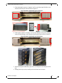
1.6.3.3 Container Mishandling
The container has shock and tilt stickers applied. These will turn
red if the container has
been mishandled or roughly handled. Upon receipt of the container look for and inspect
the shock and tilt stickers to confirm that they have not tripped. If one or more are red
notify the shipper and Mellanox. This on its own does not indicate damage to the con-
tents. But, be sure to carefully inspect
the contents if any of the shock and tilt stickers
have tripped.
Shelf
Caged nuts
Upper bracket
Lock washers
Phillips pan head
screw
Upper bracket offset
Shelf extension
Lock-down bar
Flat washers
hex head bolt
Upper bracket
washer
Flat head screw
Bottom filler panel
Top filler panel
Lock-down bar 2 hole
lock washer
Pagina se încarcă...
Pagina se încarcă...
Pagina se încarcă...
Pagina se încarcă...
Pagina se încarcă...
Pagina se încarcă...
Pagina se încarcă...
Pagina se încarcă...
Pagina se încarcă...
Pagina se încarcă...
Pagina se încarcă...
Pagina se încarcă...
Pagina se încarcă...
Pagina se încarcă...
Pagina se încarcă...
Pagina se încarcă...
Pagina se încarcă...
Pagina se încarcă...
Pagina se încarcă...
Pagina se încarcă...
Pagina se încarcă...
Pagina se încarcă...
Pagina se încarcă...
Pagina se încarcă...
Pagina se încarcă...
Pagina se încarcă...
Pagina se încarcă...
Pagina se încarcă...
Pagina se încarcă...
Pagina se încarcă...
Pagina se încarcă...
Pagina se încarcă...
Pagina se încarcă...
Pagina se încarcă...
Pagina se încarcă...
Pagina se încarcă...
Pagina se încarcă...
Pagina se încarcă...
Pagina se încarcă...
Pagina se încarcă...
Pagina se încarcă...
Pagina se încarcă...
Pagina se încarcă...
Pagina se încarcă...
Pagina se încarcă...
Pagina se încarcă...
Pagina se încarcă...
Pagina se încarcă...
Pagina se încarcă...
Pagina se încarcă...
Pagina se încarcă...
Pagina se încarcă...
Pagina se încarcă...
Pagina se încarcă...
Pagina se încarcă...
Pagina se încarcă...
Pagina se încarcă...
Pagina se încarcă...
Pagina se încarcă...
Pagina se încarcă...
Pagina se încarcă...
Pagina se încarcă...
Pagina se încarcă...
Pagina se încarcă...
Pagina se încarcă...
Pagina se încarcă...
Pagina se încarcă...
Pagina se încarcă...
Pagina se încarcă...
Pagina se încarcă...
Pagina se încarcă...
Pagina se încarcă...
Pagina se încarcă...
Pagina se încarcă...
Pagina se încarcă...
Pagina se încarcă...
Pagina se încarcă...
Pagina se încarcă...
Pagina se încarcă...
Pagina se încarcă...
Pagina se încarcă...
Pagina se încarcă...
Pagina se încarcă...
Pagina se încarcă...
Pagina se încarcă...
Pagina se încarcă...
Pagina se încarcă...
Pagina se încarcă...
Pagina se încarcă...
Pagina se încarcă...
Pagina se încarcă...
Pagina se încarcă...
Pagina se încarcă...
Pagina se încarcă...
Pagina se încarcă...
Pagina se încarcă...
Pagina se încarcă...
Pagina se încarcă...
Pagina se încarcă...
Pagina se încarcă...
Pagina se încarcă...
Pagina se încarcă...
Pagina se încarcă...
Pagina se încarcă...
-
 1
1
-
 2
2
-
 3
3
-
 4
4
-
 5
5
-
 6
6
-
 7
7
-
 8
8
-
 9
9
-
 10
10
-
 11
11
-
 12
12
-
 13
13
-
 14
14
-
 15
15
-
 16
16
-
 17
17
-
 18
18
-
 19
19
-
 20
20
-
 21
21
-
 22
22
-
 23
23
-
 24
24
-
 25
25
-
 26
26
-
 27
27
-
 28
28
-
 29
29
-
 30
30
-
 31
31
-
 32
32
-
 33
33
-
 34
34
-
 35
35
-
 36
36
-
 37
37
-
 38
38
-
 39
39
-
 40
40
-
 41
41
-
 42
42
-
 43
43
-
 44
44
-
 45
45
-
 46
46
-
 47
47
-
 48
48
-
 49
49
-
 50
50
-
 51
51
-
 52
52
-
 53
53
-
 54
54
-
 55
55
-
 56
56
-
 57
57
-
 58
58
-
 59
59
-
 60
60
-
 61
61
-
 62
62
-
 63
63
-
 64
64
-
 65
65
-
 66
66
-
 67
67
-
 68
68
-
 69
69
-
 70
70
-
 71
71
-
 72
72
-
 73
73
-
 74
74
-
 75
75
-
 76
76
-
 77
77
-
 78
78
-
 79
79
-
 80
80
-
 81
81
-
 82
82
-
 83
83
-
 84
84
-
 85
85
-
 86
86
-
 87
87
-
 88
88
-
 89
89
-
 90
90
-
 91
91
-
 92
92
-
 93
93
-
 94
94
-
 95
95
-
 96
96
-
 97
97
-
 98
98
-
 99
99
-
 100
100
-
 101
101
-
 102
102
-
 103
103
-
 104
104
-
 105
105
-
 106
106
-
 107
107
-
 108
108
-
 109
109
-
 110
110
-
 111
111
-
 112
112
-
 113
113
-
 114
114
-
 115
115
-
 116
116
-
 117
117
-
 118
118
-
 119
119
-
 120
120
-
 121
121
-
 122
122
-
 123
123
-
 124
124


Mellanox Technologies MIS5300 Hardware Installation Manual
- Categorie
- Șasiu echipament de rețea
- Tip
- Hardware Installation Manual
- Acest manual este potrivit și pentru
în alte limbi
- English: Mellanox Technologies MIS5300
Lucrări înrudite
-
Mellanox Technologies MIS5200Q-4DNC Hardware Installation Manual
-
-
-
-
-
-
-
-
Mellanox Technologies MSX6036G-2SRS Manual de utilizare
-
Mellanox Technologies SX6025 Manual de utilizare
Alte documente
-
LG PCS200R Manual de utilizare
-
i-PRO i-PRO WV-S71300-F3 Network Camera Manual de utilizare
-
-
Yamaha BRK-TV2 Ghid de instalare
-
Megger SFC250 Manual de utilizare
-
Cisco Systems MDS 9500 Manual de utilizare
-
Tetra MAX 24V Colors LED Signage Ghid de instalare
-
-
HP DesignJet 1000 Printer series Ghid de referință
-
DeLOCK 85650 Fișa cu date