www.mellanox.com
Mellanox 1U Switch and Gateway Systems
Hardware User Manual
Models: SX6005/SX6012/SX6015/SX6018/
SX6025/SX6036/SX6036G
Rev. 1.2

Document Number: MLNX-15-4047
Mellanox Technologies
2
Mellanox Technologies
350 Oakmead Parkway Suite 100
Sunnyvale, CA 94085
U.S.A.
www.mellanox.com
Tel: (408) 970-3400
Fax: (408) 970-3403
Mellanox Technologies, Ltd.
Hakidma 26
Ofer Industrial Park
Yokneam 2069200
Israel
www.mellanox.com
Tel: +972 (0)74 723 7200
Fax: +972 (0)4 959 3245
© Copyright 2015. Mellanox Technologies. All Rights Reserved.
Mellanox®, Mellanox logo, BridgeX®, ConnectX®, Connect-IB®, CoolBox®, CORE-Direct®, GPUDirect®, InfiniBridge®,
InfiniHost®, InfiniScale®, Kotura®, Kotura logo, Mellanox Connect. Accelerate. Outperform logo, Mellanox Federal
Systems® Mellanox Open Ethernet®, MetroX®, MLNX-OS®, Open Ethernet logo, PhyX®, ScalableHPC®, SwitchX®,
TestX®, The Generation of Open Ethernet logo, UFM®, Virtual Protocol Interconnect®, Voltaire® and Voltaire logo are
registered trademarks of Mellanox Technologies, Ltd.
CyPU™, ExtendX™, FabricIT™, FPGADirect™, HPC-X™, Mellanox Care™, Mellanox CloudX™, Mellanox NEO™,
Mellanox Open Ethernet™, Mellanox PeerDirect™, Mellanox Virtual Modular Switch™, MetroDX™, NVMeDirect™,
StPU™, Switch-IB™, Unbreakable-Link™ are trademarks of Mellanox Technologies, Ltd.
All other trademarks are property of their respective owners.
NOTE:
THIS HARDWARE, SOFTWARE OR TEST SUITE PRODUCT (“PRODUCT(S)”) AND ITS RELATED
DOCUMENTATION ARE PROVIDED BY MELLANOX TECHNOLOGIES “AS-IS” WITH ALL FAULTS OF ANY
KIND AND SOLELY FOR THE PURPOSE OF AIDING THE CUSTOMER IN TESTING APPLICATIONS THAT USE
THE PRODUCTS IN DESIGNATED SOLUTIONS. THE CUSTOMER'S MANUFACTURING TEST ENVIRONMENT
HAS NOT MET THE STANDARDS SET BY MELLANOX TECHNOLOGIES TO FULLY QUALIFY THE PRODUCT(S)
AND/OR THE SYSTEM USING IT. THEREFORE, MELLANOX TECHNOLOGIES CANNOT AND DOES NOT
GUARANTEE OR WARRANT THAT THE PRODUCTS WILL OPERATE WITH THE HIGHEST QUALITY. ANY
EXPRESS OR IMPLIED WARRANTIES, INCLUDING, BUT NOT LIMITED TO, THE IMPLIED WARRANTIES OF
MERCHANTABILITY, FITNESS FOR A PARTICULAR PURPOSE AND NONINFRINGEMENT ARE DISCLAIMED.
IN NO EVENT SHALL MELLANOX BE LIABLE TO CUSTOMER OR ANY THIRD PARTIES FOR ANY DIRECT,
INDIRECT, SPECIAL, EXEMPLARY, OR CONSEQUENTIAL DAMAGES OF ANY KIND (INCLUDING, BUT NOT
LIMITED TO, PAYMENT FOR PROCUREMENT OF SUBSTITUTE GOODS OR SERVICES; LOSS OF USE, DATA,
OR PROFITS; OR BUSINESS INTERRUPTION) HOWEVER CAUSED AND ON ANY THEORY OF LIABILITY,
WHETHER IN CONTRACT, STRICT LIABILITY, OR TORT (INCLUDING NEGLIGENCE OR OTHERWISE)
ARISING IN ANY WAY FROM THE USE OF THE PRODUCT(S) AND RELATED DOCUMENTATION EVEN IF
ADVISED OF THE POSSIBILITY OF SUCH DAMAGE.

Mellanox Technologies
3
Table of Contents
Revision History . . . . . . . . . . . . . . . . . . . . . . . . . . . . . . . . . . . . . . . . . . . . . . . . . . . . . . . . . . . 8
About this Manual . . . . . . . . . . . . . . . . . . . . . . . . . . . . . . . . . . . . . . . . . . . . . . . . . . . . . . . . . 9
Chapter 1 Introduction to Mellanox SX60XX Systems . . . . . . . . . . . . . . . . . . . . . . . . . 11
1.1 Overview . . . . . . . . . . . . . . . . . . . . . . . . . . . . . . . . . . . . . . . . . . . . . . . . . . . . . . . 11
1.2 Speed and Switching . . . . . . . . . . . . . . . . . . . . . . . . . . . . . . . . . . . . . . . . . . . . . . 12
1.3 Management Interfaces and FRUs. . . . . . . . . . . . . . . . . . . . . . . . . . . . . . . . . . . . 13
1.4 Features . . . . . . . . . . . . . . . . . . . . . . . . . . . . . . . . . . . . . . . . . . . . . . . . . . . . . . . . 13
1.4.1 Network Management Features . . . . . . . . . . . . . . . . . . . . . . . . . . . . . . . . . . . . . . 13
1.4.2 InfiniBand Features. . . . . . . . . . . . . . . . . . . . . . . . . . . . . . . . . . . . . . . . . . . . . . . . 13
1.4.3 Gateway Features . . . . . . . . . . . . . . . . . . . . . . . . . . . . . . . . . . . . . . . . . . . . . . . . . 14
1.5 Certifications . . . . . . . . . . . . . . . . . . . . . . . . . . . . . . . . . . . . . . . . . . . . . . . . . . . . 14
1.6 Ordering Information. . . . . . . . . . . . . . . . . . . . . . . . . . . . . . . . . . . . . . . . . . . . . . 14
Chapter 2 Installation . . . . . . . . . . . . . . . . . . . . . . . . . . . . . . . . . . . . . . . . . . . . . . . . . . . . 17
2.1 Safety Warnings. . . . . . . . . . . . . . . . . . . . . . . . . . . . . . . . . . . . . . . . . . . . . . . . . . 17
2.2 Air Flow. . . . . . . . . . . . . . . . . . . . . . . . . . . . . . . . . . . . . . . . . . . . . . . . . . . . . . . . 18
2.3 Package Contents. . . . . . . . . . . . . . . . . . . . . . . . . . . . . . . . . . . . . . . . . . . . . . . . . 20
2.4 Mounting Options . . . . . . . . . . . . . . . . . . . . . . . . . . . . . . . . . . . . . . . . . . . . . . . . 21
2.4.1 19” Systems Mounting . . . . . . . . . . . . . . . . . . . . . . . . . . . . . . . . . . . . . . . . . . . . . 21
2.4.2 Side-by-Side . . . . . . . . . . . . . . . . . . . . . . . . . . . . . . . . . . . . . . . . . . . . . . . . . . . . . 26
2.4.3 Table Top . . . . . . . . . . . . . . . . . . . . . . . . . . . . . . . . . . . . . . . . . . . . . . . . . . . . . . . 30
2.5 Grounding . . . . . . . . . . . . . . . . . . . . . . . . . . . . . . . . . . . . . . . . . . . . . . . . . . . . . . 32
2.6 Cable Installation. . . . . . . . . . . . . . . . . . . . . . . . . . . . . . . . . . . . . . . . . . . . . . . . . 33
2.6.1 Using a Breakout Cable . . . . . . . . . . . . . . . . . . . . . . . . . . . . . . . . . . . . . . . . . . . . 33
2.7 Initial Power On. . . . . . . . . . . . . . . . . . . . . . . . . . . . . . . . . . . . . . . . . . . . . . . . . . 36
2.8 System Bring-Up . . . . . . . . . . . . . . . . . . . . . . . . . . . . . . . . . . . . . . . . . . . . . . . . 38
2.8.1 Configuring Network Attributes . . . . . . . . . . . . . . . . . . . . . . . . . . . . . . . . . . . . . . 38
2.8.2 Remote Connection. . . . . . . . . . . . . . . . . . . . . . . . . . . . . . . . . . . . . . . . . . . . . . . . 42
2.9 FRU Replacements . . . . . . . . . . . . . . . . . . . . . . . . . . . . . . . . . . . . . . . . . . . . . . . 43
2.9.1 Power Supply and Fans . . . . . . . . . . . . . . . . . . . . . . . . . . . . . . . . . . . . . . . . . . . . 43
Chapter 3 Interfaces . . . . . . . . . . . . . . . . . . . . . . . . . . . . . . . . . . . . . . . . . . . . . . . . . . . . . 46
3.1 Data Interfaces. . . . . . . . . . . . . . . . . . . . . . . . . . . . . . . . . . . . . . . . . . . . . . . . . . . 46
3.1.1 Speed. . . . . . . . . . . . . . . . . . . . . . . . . . . . . . . . . . . . . . . . . . . . . . . . . . . . . . . . . . . 46
3.1.2 RS232 (Console) . . . . . . . . . . . . . . . . . . . . . . . . . . . . . . . . . . . . . . . . . . . . . . . . . . 47
3.1.3 Management . . . . . . . . . . . . . . . . . . . . . . . . . . . . . . . . . . . . . . . . . . . . . . . . . . . . . 47
3.1.4 USB. . . . . . . . . . . . . . . . . . . . . . . . . . . . . . . . . . . . . . . . . . . . . . . . . . . . . . . . . . . . 47
3.1.5 I2C. . . . . . . . . . . . . . . . . . . . . . . . . . . . . . . . . . . . . . . . . . . . . . . . . . . . . . . . . . . . . 48
3.1.6 Reset Button . . . . . . . . . . . . . . . . . . . . . . . . . . . . . . . . . . . . . . . . . . . . . . . . . . . . . 48
3.2 LEDs . . . . . . . . . . . . . . . . . . . . . . . . . . . . . . . . . . . . . . . . . . . . . . . . . . . . . . . . . . 48
3.2.1 LED Notifications . . . . . . . . . . . . . . . . . . . . . . . . . . . . . . . . . . . . . . . . . . . . . . . . . 48
3.3 Inventory Pull-out Tab. . . . . . . . . . . . . . . . . . . . . . . . . . . . . . . . . . . . . . . . . . . . . 53

Mellanox Technologies
4
Chapter 4 Software Management. . . . . . . . . . . . . . . . . . . . . . . . . . . . . . . . . . . . . . . . . . . 55
4.1 InfiniBand Subnet Manager. . . . . . . . . . . . . . . . . . . . . . . . . . . . . . . . . . . . . . . . . 55
4.2 Fabric Inspector (Diagnostics). . . . . . . . . . . . . . . . . . . . . . . . . . . . . . . . . . . . . . . 55
4.3 Upgrading Software (on Managed Systems). . . . . . . . . . . . . . . . . . . . . . . . . . . . 56
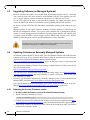
4.4 Updating Firmware on Externally Managed Systems . . . . . . . . . . . . . . . . . . . . . 56
4.4.1 Obtaining the Current Firmware version . . . . . . . . . . . . . . . . . . . . . . . . . . . . . . . 56
4.4.2 Reprogramming the System Through The I2C Port . . . . . . . . . . . . . . . . . . . . . . . 57
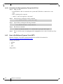
4.4.3 How to Get Mellanox Firmware Tools (MFT) . . . . . . . . . . . . . . . . . . . . . . . . . . . 58
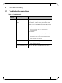
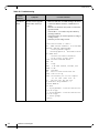
Chapter 5 Troubleshooting . . . . . . . . . . . . . . . . . . . . . . . . . . . . . . . . . . . . . . . . . . . . . . . . 59
5.1 Troubleshooting Instructions. . . . . . . . . . . . . . . . . . . . . . . . . . . . . . . . . . . . . . . . 59
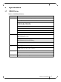
Chapter 6 Specifications . . . . . . . . . . . . . . . . . . . . . . . . . . . . . . . . . . . . . . . . . . . . . . . . . . 61
6.1 SX6005 Series . . . . . . . . . . . . . . . . . . . . . . . . . . . . . . . . . . . . . . . . . . . . . . . . . . . 61
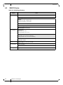
6.2 SX6012 Series . . . . . . . . . . . . . . . . . . . . . . . . . . . . . . . . . . . . . . . . . . . . . . . . . . . 62
6.3 SX6015 Series . . . . . . . . . . . . . . . . . . . . . . . . . . . . . . . . . . . . . . . . . . . . . . . . . . . 63
6.4 SX6018 Series . . . . . . . . . . . . . . . . . . . . . . . . . . . . . . . . . . . . . . . . . . . . . . . . . . . 64
6.5 SX6025 Series . . . . . . . . . . . . . . . . . . . . . . . . . . . . . . . . . . . . . . . . . . . . . . . . . . . 65
6.6 SX6036 Series . . . . . . . . . . . . . . . . . . . . . . . . . . . . . . . . . . . . . . . . . . . . . . . . . . . 66
6.7 SX6036G Series. . . . . . . . . . . . . . . . . . . . . . . . . . . . . . . . . . . . . . . . . . . . . . . . . . 67
Appendix A Accessory and Replacement Parts . . . . . . . . . . . . . . . . . . . . . . . . . . . . . . . 68
Appendix B Thermal Threshold Definitions . . . . . . . . . . . . . . . . . . . . . . . . . . . . . . . . . 69
Appendix C Interface Specifications . . . . . . . . . . . . . . . . . . . . . . . . . . . . . . . . . . . . . . . . 70
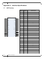
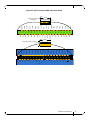
C.1 QSFP Interface . . . . . . . . . . . . . . . . . . . . . . . . . . . . . . . . . . . . . . . . . . . . . . . . 70
C.2 RJ-45 CONSOLE and I2C Interface . . . . . . . . . . . . . . . . . . . . . . . . . . . . . . . 72
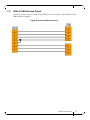
C.3 RJ45 to DB9 Harness Pinout . . . . . . . . . . . . . . . . . . . . . . . . . . . . . . . . . . . . . 73
Appendix D Disassembly and Disposal . . . . . . . . . . . . . . . . . . . . . . . . . . . . . . . . . . . . . . 74
D.1 Disassembly Procedure . . . . . . . . . . . . . . . . . . . . . . . . . . . . . . . . . . . . . . . . . 74
D.2 Disposal . . . . . . . . . . . . . . . . . . . . . . . . . . . . . . . . . . . . . . . . . . . . . . . . . . . . . 74
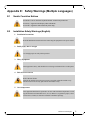
Appendix E Safety Warnings (Multiple Languages) . . . . . . . . . . . . . . . . . . . . . . . . . . . 75
E.1 Nordic Countries Notices . . . . . . . . . . . . . . . . . . . . . . . . . . . . . . . . . . . . . . . . 75
E.2 Installation Safety Warnings (English) . . . . . . . . . . . . . . . . . . . . . . . . . . . . . 75
E.3 (תירבע) הנקתהב תוחיטב תורהזא . . . . . . . . . . . . . . . . . . . . . . . . . . . . . . . . . . . . . . 78
E.4 安裝安全性警告 (Chinese) . . . . . . . . . . . . . . . . . . . . . . . . . . . . . . . . . . . . . . 82
E.5 Avertissements de sécurité pour l'installation (French) . . . . . . . . . . . . . . . . . 85
E.6 Installation Sicherheitshinweise(German) . . . . . . . . . . . . . . . . . . . . . . . . . . . 88
E.7 Advertencias de seguridad de instalación (Spanish) . . . . . . . . . . . . . . . . . . . 92
E.8 Предупреждения по технике безопасности при установке (Russian) . . . 95
E.9 Avertismente privind siguranţa la instalare (Romanian) . . . . . . . . . . . . . . . . 98
E.10 Sigurnosna upozorenja za instaliranje (Croatian). . . . . . . . . . . . . . . . . . . . . 102
E.11 Avvertenze di sicurezza per l’installazione (italiano) . . . . . . . . . . . . . . . . . 105
E.12 Montaj Güvenlik Uyarıları (Türkçe) . . . . . . . . . . . . . . . . . . . . . . . . . . . . . . 109

Mellanox Technologies
5
List of Figures
Figure 1: InfiniBand Systems Family Front Side View . . . . . . . . . . . . . . . . . . . . . . . . . . . . . . . . . .12
Figure 2: Air Flow Direction Marking - Connector Side Inlet to Power Side Outlet . . . . . . . . . . .19
Figure 3: Air Flow Direction Marking - Power Side Inlet to Connector Side Outlet . . . . . . . . . . .19
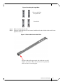
Figure 4: Rack Rail Kit Parts . . . . . . . . . . . . . . . . . . . . . . . . . . . . . . . . . . . . . . . . . . . . . . . . . . . . . .21
Figure 5: Screwing on the Rail . . . . . . . . . . . . . . . . . . . . . . . . . . . . . . . . . . . . . . . . . . . . . . . . . . . . .22
Figure 6: Inserting the Caged Nuts . . . . . . . . . . . . . . . . . . . . . . . . . . . . . . . . . . . . . . . . . . . . . . . . .23
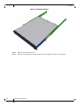
Figure 7: Slide the Rail into the Rail Slide . . . . . . . . . . . . . . . . . . . . . . . . . . . . . . . . . . . . . . . . . . .23
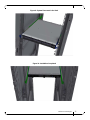
Figure 8: Installing the Slides . . . . . . . . . . . . . . . . . . . . . . . . . . . . . . . . . . . . . . . . . . . . . . . . . . . . .24
Figure 9: System Placement in the Rack . . . . . . . . . . . . . . . . . . . . . . . . . . . . . . . . . . . . . . . . . . . . .25
Figure 10: Installation Completed . . . . . . . . . . . . . . . . . . . . . . . . . . . . . . . . . . . . . . . . . . . . . . . . . . .25
Figure 11: Installation Kit Parts for a Side by Side Installation . . . . . . . . . . . . . . . . . . . . . . . . . . . .26
Figure 12: Screw on the System Mounted Rails . . . . . . . . . . . . . . . . . . . . . . . . . . . . . . . . . . . . . . . .27
Figure 13: Two Systems Frame . . . . . . . . . . . . . . . . . . . . . . . . . . . . . . . . . . . . . . . . . . . . . . . . . . . .28
Figure 14: Placement of Frame in the Rack . . . . . . . . . . . . . . . . . . . . . . . . . . . . . . . . . . . . . . . . . . . .28
Figure 15: Placing the Spacer in the Rack . . . . . . . . . . . . . . . . . . . . . . . . . . . . . . . . . . . . . . . . . . . . .29
Figure 16: Using the Spacer Bushings . . . . . . . . . . . . . . . . . . . . . . . . . . . . . . . . . . . . . . . . . . . . . . . .29
Figure 17: Insert System into Frame . . . . . . . . . . . . . . . . . . . . . . . . . . . . . . . . . . . . . . . . . . . . . . . . .30
Figure 18: Placing the Bumpers . . . . . . . . . . . . . . . . . . . . . . . . . . . . . . . . . . . . . . . . . . . . . . . . . . . . .31
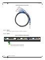
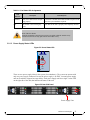
Figure 19: Cable Orientation . . . . . . . . . . . . . . . . . . . . . . . . . . . . . . . . . . . . . . . . . . . . . . . . . . . . . . .33
Figure 20: Breakout or Fanout Cable . . . . . . . . . . . . . . . . . . . . . . . . . . . . . . . . . . . . . . . . . . . . . . . . .34
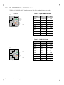
Figure 21: SX6018 Port Splitting Options . . . . . . . . . . . . . . . . . . . . . . . . . . . . . . . . . . . . . . . . . . . . .34
Figure 22: 6036(G) Port Splitting Options . . . . . . . . . . . . . . . . . . . . . . . . . . . . . . . . . . . . . . . . . . . . .35
Figure 23: Examples of Port Mapping Assignment . . . . . . . . . . . . . . . . . . . . . . . . . . . . . . . . . . . . . .36
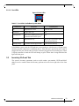
Figure 24: System Status LEDs 5 Minutes After Power On . . . . . . . . . . . . . . . . . . . . . . . . . . . . . . .37
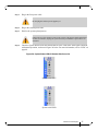
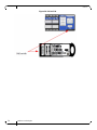
Figure 25: Two Power Inlets - Electric Caution Notifications . . . . . . . . . . . . . . . . . . . . . . . . . . . . .38
Figure 26: Power Supply Unit Extraction . . . . . . . . . . . . . . . . . . . . . . . . . . . . . . . . . . . . . . . . . . . . .44
Figure 27: PS Unit Pulled Out . . . . . . . . . . . . . . . . . . . . . . . . . . . . . . . . . . . . . . . . . . . . . . . . . . . . . .44
Figure 28: Fan Module Latches . . . . . . . . . . . . . . . . . . . . . . . . . . . . . . . . . . . . . . . . . . . . . . . . . . . . .45
Figure 29: System Status LEDs - Front and Rear sides . . . . . . . . . . . . . . . . . . . . . . . . . . . . . . . . . . .49
Figure 30: Fan Status LED - Front and Rear sides . . . . . . . . . . . . . . . . . . . . . . . . . . . . . . . . . . . . . .50
Figure 31: Power Status LED . . . . . . . . . . . . . . . . . . . . . . . . . . . . . . . . . . . . . . . . . . . . . . . . . . . . . .51
Figure 32: Rear Side Panel . . . . . . . . . . . . . . . . . . . . . . . . . . . . . . . . . . . . . . . . . . . . . . . . . . . . . . . .51
Figure 33: Port LEDs . . . . . . . . . . . . . . . . . . . . . . . . . . . . . . . . . . . . . . . . . . . . . . . . . . . . . . . . . . . . .53
Figure 34: Pull-out Tab . . . . . . . . . . . . . . . . . . . . . . . . . . . . . . . . . . . . . . . . . . . . . . . . . . . . . . . . . . .54
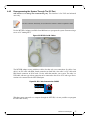
Figure 35: MTUSB-1 with Cables . . . . . . . . . . . . . . . . . . . . . . . . . . . . . . . . . . . . . . . . . . . . . . . . . . .57
Figure 36: I2C Cable Connected to SX6025 . . . . . . . . . . . . . . . . . . . . . . . . . . . . . . . . . . . . . . . . . . .57

Mellanox Technologies
6
Figure 37: QSFP Connector Male and Female Views . . . . . . . . . . . . . . . . . . . . . . . . . . . . . . . . . . . .71
Figure 38: RJ45 to DB9 Harness Pinout . . . . . . . . . . . . . . . . . . . . . . . . . . . . . . . . . . . . . . . . . . . . . .73

Mellanox Technologies
7
List of Tables
Table 1: Revision History Table . . . . . . . . . . . . . . . . . . . . . . . . . . . . . . . . . . . . . . . . . . . . . . . . . . . .8
Table 2: References . . . . . . . . . . . . . . . . . . . . . . . . . . . . . . . . . . . . . . . . . . . . . . . . . . . . . . . . . . . . .9
Table 3: Speed and Switching Capabilities . . . . . . . . . . . . . . . . . . . . . . . . . . . . . . . . . . . . . . . . . .12
Table 4: Management Interfaces and FRUs . . . . . . . . . . . . . . . . . . . . . . . . . . . . . . . . . . . . . . . . . .13
Table 5: Ordering Part Numbers (OPNs) . . . . . . . . . . . . . . . . . . . . . . . . . . . . . . . . . . . . . . . . . . . .14
Table 6: Air Flow Label Legend . . . . . . . . . . . . . . . . . . . . . . . . . . . . . . . . . . . . . . . . . . . . . . . . . . .18
Table 7: Installation Kit Options . . . . . . . . . . . . . . . . . . . . . . . . . . . . . . . . . . . . . . . . . . . . . . . . . .21
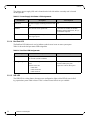
Table 8: Port Splitting Options . . . . . . . . . . . . . . . . . . . . . . . . . . . . . . . . . . . . . . . . . . . . . . . . . . . .35
Table 9: Serial Terminal Program Configuration . . . . . . . . . . . . . . . . . . . . . . . . . . . . . . . . . . . . . .39
Table 10: Configuration Wizard Session - DHCP . . . . . . . . . . . . . . . . . . . . . . . . . . . . . . . . . . . . . .39
Table 11: Configuration Wizard Session - Static IP Configuration . . . . . . . . . . . . . . . . . . . . . . . . .41
Table 12: Status LEDs . . . . . . . . . . . . . . . . . . . . . . . . . . . . . . . . . . . . . . . . . . . . . . . . . . . . . . . . . . .49
Table 13: System Status LED Assignments . . . . . . . . . . . . . . . . . . . . . . . . . . . . . . . . . . . . . . . . . . .50
Table 14: Fan Status LED Assignments . . . . . . . . . . . . . . . . . . . . . . . . . . . . . . . . . . . . . . . . . . . . . .50
Table 15: Power Supply Unit Status LED Assignments . . . . . . . . . . . . . . . . . . . . . . . . . . . . . . . . .52
Table 16: Bad Port LED Assignments . . . . . . . . . . . . . . . . . . . . . . . . . . . . . . . . . . . . . . . . . . . . . . .52
Table 17: Port LEDs in InfiniBand System Mode . . . . . . . . . . . . . . . . . . . . . . . . . . . . . . . . . . . . . .53
Table 18: Troubleshooting . . . . . . . . . . . . . . . . . . . . . . . . . . . . . . . . . . . . . . . . . . . . . . . . . . . . . . . .59
Table 19: SX6005 Specifications . . . . . . . . . . . . . . . . . . . . . . . . . . . . . . . . . . . . . . . . . . . . . . . . . . .61
Table 20: SX6012 Specifications . . . . . . . . . . . . . . . . . . . . . . . . . . . . . . . . . . . . . . . . . . . . . . . . . . .62
Table 21: SX6015 Specifications . . . . . . . . . . . . . . . . . . . . . . . . . . . . . . . . . . . . . . . . . . . . . . . . . . .63
Table 22: SX6018 Specifications . . . . . . . . . . . . . . . . . . . . . . . . . . . . . . . . . . . . . . . . . . . . . . . . . . .64
Table 23: SX6025 Specifications . . . . . . . . . . . . . . . . . . . . . . . . . . . . . . . . . . . . . . . . . . . . . . . . . . .65
Table 24: SX6036 Specifications . . . . . . . . . . . . . . . . . . . . . . . . . . . . . . . . . . . . . . . . . . . . . . . . . . .66
Table 25: SX6036G Specifications . . . . . . . . . . . . . . . . . . . . . . . . . . . . . . . . . . . . . . . . . . . . . . . . . .67
Table 26: OPNs for Replacement Parts . . . . . . . . . . . . . . . . . . . . . . . . . . . . . . . . . . . . . . . . . . . . . .68
Table 27: RJ-45 CONSOLE Pinout . . . . . . . . . . . . . . . . . . . . . . . . . . . . . . . . . . . . . . . . . . . . . . . . .72
Table 28: RJ-45 I2C Pinout . . . . . . . . . . . . . . . . . . . . . . . . . . . . . . . . . . . . . . . . . . . . . . . . . . . . . . .72

Mellanox Technologies
8
Revision History
Table 1 - Revision History Table
Date Revision Description
June 2015 1.2 Added Hebrew safety warnings
Added Japan VCCI Statement
Updated “Specifications”
Updated “Mounting Options”
January 2015 1.1 Minor formatting edits
January 2015 1.0 First release of the new edition

Mellanox Technologies
9
About this Manual
This manual describes the installation and basic use of the Mellanox InfiniBand/VPI systems.
Intended Audience
This manual is intended for IT managers and system administrators.
References
Table 2 - References
Document Description
InfiniBand Architecture Specifica-
tion, Volume 1, Release 1.2.1 and
1.3
The InfiniBand Architecture Specification that is provided by IBTA
SwitchX® Switch System
Hardware Release Notes
For possible hardware issues see the switch support product page. This
document can be found on the support web page for this product.
MLNX-OS® User Manual This document contains information regarding configuring and manag-
ing MLNX-OS software- see http://www.mellanox.com/page/mlnx_os.

Mellanox Technologies
10
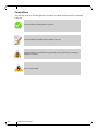
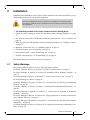
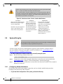
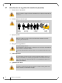
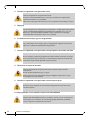
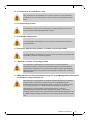
Conventions
The following icons are used throughout this document to indicate information that is important
to the user.
This icon makes recommendations to the user.
This icon indicates information that is helpful to the user.
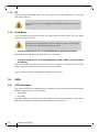
This icon indicates a situation that can potentially cause personal injury or damage to
hardware or software.
Risk of electric shock!

Mellanox Technologies
11
1 Introduction to Mellanox SX60XX Systems
1.1 Overview
The SX60XX systems provide the highest performing fabric solution in a 1U form factor by
delivering up to 4Tb/s of non-blocking bandwidth with 200ns port-to-port latency.
These systems are the industry's most cost-effective building blocks for embedded systems and
storage with a need for low port density systems. Whether looking at price-to-performance or
energy-to-performance, these systems offer superior performance, power and space, reducing
capital and operating expenses, and providing the best return-on-investment. The systems are an
ideal choice for smaller departmental or back-end clustering uses with high-performance needs,
such as storage, data base and GPGPU clusters.
Powerful servers combined with high-performance storage and applications that use increasingly
complex computations are causing data bandwidth requirements to spiral upward. As servers are
deployed with next generation processors, High-Performance Computing (HPC) environments
and Enterprise Data Centers (EDC) need every last bit of bandwidth delivered with Mellanox’s
FDR InfiniBand systems.
Built with Mellanox’s sixth generation SwitchX®-2 InfiniBand FDR 56Gb/s system device,
these standalone systems are an ideal choice for top-of-rack leaf connectivity or for building
small to extremely large sized clusters.
These systems enable efficient computing with features such as static routing, adaptive routing,
and advanced congestion management. These features ensure the maximum effective fabric
bandwidth by eliminating congestion.
The managed systems comes with an onboard subnet manager, enabling simple, out-of-the-box
fabric bring-up for up to 648 nodes. MLNX-OS® software delivers complete chassis manage
-
ment of firmware, power supplies, fans, ports and other interfaces.
Mellanox’s edge systems can also be coupled with Mellanox’s Unified Fabric Manager (UFM®)
software for managing scale-out InfiniBand computing environments. UFM enables data center
operators to efficiently provision, monitor and operate the modern data center fabric. UFM
boosts application performance and ensures that the fabric is up and running at all times.
InfiniBand systems come as internally or externally managed. Internally managed systems come
with a CPU that runs the management software (MLNX-OS®) and management ports which are
used to transfer management traffic into the system. Externally managed systems come without
the CPU and management ports and are managed using firmware tools.
Mellanox's InfiniBand to Ethernet gateway, built with Mellanox's SwitchX®-2 based systems,
provides the most cost-effective, high-performance solution for data center unified connectivity
solutions. Mellanox's gateways enable data centers to operate at up to 56Gb/s network speeds
while seamlessly connecting to 1, 10 and 40GbE networks with low latency (400ns). Existing
LAN infrastructures and management practices can be preserved, easing deployment and provid
-
ing significant return-on-investment.

Introduction to Mellanox SX60XX Systems
Mellanox Technologies
12
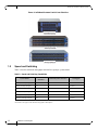
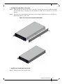
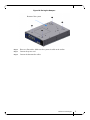
Figure 1: InfiniBand Systems Family Front Side View
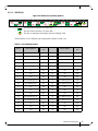
1.2 Speed and Switching
Table 3 describes maximum throughput and interface speed per system model.
*The switches can support 10Gb/s interfaces using QSFP to SFP adapters
Table 3 - Speed and Switching Capabilities
System Model
10GbE* SFP+
Interfaces
40/56GbE QSFP+ Interfaces Throughput
SX6005 (externally managed) N/A 12 1.34Tb/s
SX6012 (internally managed) N/A 12 1.34Tb/s
SX6015 (externally managed) N/A 18 2.02Tb/s
SX6018 (internally managed) N/A 18 2.02Tb/s
SX6025 (externally managed) N/A 36 4.03Tb/s
SX6036G (internally managed) N/A 36 4.03Tb/s

Mellanox Technologies
13
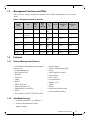
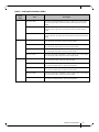
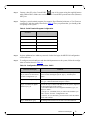
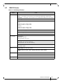
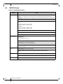
1.3 Management Interfaces and FRUs
Table 4 lists the various management interfaces and available replacement parts per system
model.
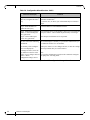
1.4 Features
1.4.1 Network Management Features
1.4.2 InfiniBand Features
• Compliant with IBTA 1.2.1 and IBTA 1.3
• Link Layer Retransmission (LLR)
• Adaptive routing*
Table 4 - Management Interfaces and FRUs
System
Model
USB
MGT
Ports
Qty.
MGT
Ports
Location
I
2
C
Console
Replaceable
PSU
Replaceable
Fan
SX6005 N/A N/A N/A Front
Rear
N/A N/A N/A
SX6012 Front
(mini-USB)
1 Front Rear Front N/A N/A
SX6015 N/A N/A N/A Front
Rear
N/A 2 FRUs 1 FRU
SX6018 Front 2 Front (x2) Rear Front 2 FRUs 1 FRU
SX6025 N/A N/A N/A Front
Rear
N/A 2 FRUs 1 FRU
SX6036 Front 2 Front (x2) Rear Front 2 FRUs 1 FRU
SX6036G Front 2 Front (x2) Rear Front 2 FRUs 1 FRU
• 100/1000 MbE Management port (managed
systems only)
• In-Band Management
• Serial Console Port
• RADIUS
•TACACS+
• LDAP
•SSHv2
• DHCP/Zeroconf
• Industry Standard CLI
• Management over IPv4/IPv6
•Telnet
• File download via SCP, FTP & TFTP client
•Dual SW Image
• Network Time Protocol (NTP)
•Syslog
• Auto Temperature Control
• System alarms
• Port Counters
• Event notification
• SNMP v1,v2,v3
•E-Mail
•WebUI
• Predefined scheduled scripts
• System health monitoring

Introduction to Mellanox SX60XX Systems
Mellanox Technologies
14
• Congestion control**
• Port mirroring**
• Fabric Inspector
• Embedded Subnet Manager (SM)
* Roadmap feature - this feature is not yet available.
** Supported in managed systems only.
1.4.3 Gateway Features
• InfiniBand to Ethernet bridging
• High Availability
1.5 Certifications
The list of certifications (such as EMC, Safety and others) per system for different regions of the
world is located on the Mellanox website at:
http://www.mellanox.com/page/environmental_compliance
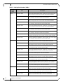
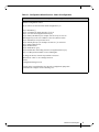
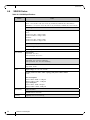
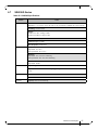
1.6 Ordering Information
the following table lists ordering information for the available systems. Please pay attention to
the airflow direction when ordering your system. For more details, see
“Air Flow” on page 18._
Gateway is supported inbox in SX6036G. In other systems it can be achieved via
license upgrade.
Table 5 - Ordering Part Numbers (OPNs)
System
Model
OPN Description
SX6005 MSX6005F-1BFS SwitchX®-2 based FDR InfiniBand 1U Switch, 12 QSFP+ ports, 1 Power Supply
(AC), unmanaged, short depth, P2C airflow, Rail Kit must be purchased separately,
RoHS6
MSX6005T-1BFS SwitchX®-2 based FDR-10 InfiniBand 1U Switch, 12 QSFP+ ports, 1 Power Supply
(AC), unmanaged, short depth, P2C airflow, Rail Kit must be purchased separately,
RoHS6
SX6012 MSX6012F-1BFS SwitchX®-2 based FDR InfiniBand 1U Switch, 12 QSFP+ ports, 1 Power Supply
(AC), PPC460, short depth, P2C airflow, Rail Kit must be purchased separately,
RoHS6
MSX6012F-1BRS SwitchX®-2 based FDR InfiniBand 1U Switch, 12 QSFP+ ports, 1 Power Supply
(AC), PPC460, short depth, C2P airflow, Rail Kit must be purchased separately,
RoHS6
MSX6012F-2BFS SwitchX®-2 based FDR InfiniBand 1U Switch, 12 QSFP+ ports, 2 Power Supplies
(AC), PPC460, short depth, P2C airflow, Rail Kit must be purchased separately,
RoHS6

Mellanox Technologies
15
MSX6012F-2BRS SwitchX®-2 based FDR InfiniBand 1U Switch, 12 QSFP+ ports, 2 Power Supply
(AC), PPC460, short depth, C2P airflow, Rail Kit must be purchased separately,
RoHS6
MSX6012T-1BFS SwitchX®-2 based FDR-10 InfiniBand 1U Switch, 12 QSFP+ ports, 1 Power Supply
(AC), PPC460, short depth, P2C airflow, Rail Kit must be purchased separately,
RoHS6
MSX6012T-2BFS SwitchX®-2 based FDR-10 InfiniBand 1U Switch, 12 QSFP+ ports, 2 Power Sup-
plies (AC), PPC460, short depth, P2C airflow, Rail Kit must be purchased separately,
RoHS6
SX6015 MSX6015F-1BRS SwitchX®-2 based FDR InfiniBand 1U Switch, 18 QSFP+ ports, 1 Power Supply
(AC), unmanaged, short depth, C2P airflow, Rail Kit, RoHS6
MSX6015F-1SFS SwitchX®-2 based FDR InfiniBand 1U Switch, 18 QSFP+ ports, 1 Power Supply
(AC), unmanaged, standard depth, P2C airflow, Rail Kit, RoHS6
MSX6015T-1BRS SwitchX®-2 based FDR-10 InfiniBand 1U Switch, 18 QSFP+ ports, 1 Power Supply
(AC), unmanaged, short depth, C2P airflow, Rail Kit, RoHS6
MSX6015T-1SFS SwitchX®-2 based FDR-10 InfiniBand 1U Switch, 18 QSFP+ ports, 1 Power Supply
(AC), unmanaged, standard depth, P2C airflow, Rail Kit, RoHS6
SX6018 MSX6018F-1BRS SwitchX®-2 based FDR InfiniBand 1U Switch, 18 QSFP+ ports, 1 Power Supply
(AC), PPC460, short depth, C2P airflow, Rail Kit, RoHS6
MSX6018F-1SFS SwitchX®-2 based FDR InfiniBand 1U Switch, 18 QSFP+ ports, 1 Power Supply
(AC), PPC460, standard depth, P2C airflow, Rail Kit, RoHS6
MSX6018F-2SRS SwitchX®-2 based FDR InfiniBand 1U Switch, 18 QSFP+ ports, 2 Power Supplies
(AC), PPC460, standard depth, C2P airflow, Rail Kit, RoHS6
MSX6018T-1BRS SwitchX®-2 based FDR-10 InfiniBand 1U Switch, 18 QSFP+ ports, 1 Power Supply
(AC), PPC460, short depth, C2P airflow, Rail Kit, RoHS6
MSX6018T-1SFS SwitchX®-2 based FDR-10 InfiniBand 1U Switch, 18 QSFP+ ports, 1 Power Supply
(AC), PPC460, standard depth, P2C airflow, Rail Kit, RoHS6
Table 5 - Ordering Part Numbers (OPNs)
System
Model
OPN Description

Introduction to Mellanox SX60XX Systems
Mellanox Technologies
16
SX6025 MSX6025F-1BRR SwitchX® based FDR InfiniBand Switch, 36 QSFP ports, 1 Power Supply, Short
depth, Unmanaged, Connector side to PSU side airflow, Rail Kit and RoHS6
MSX6025F-1BRS SwitchX®-2 based FDR InfiniBand 1U Switch, 36 QSFP+ ports, 1 Power Supply
(AC), unmanaged, short depth, C2P airflow, Rail Kit, RoHS6
MSX6025F-1SFR SwitchX® based FDR InfiniBand Switch, 36 QSFP ports, 1 Power Supply, Standard
depth, Unmanaged, PSU side to Connector side airflow, Rail Kit and RoHS6
MSX6025F-1SFS SwitchX®-2 based FDR InfiniBand 1U Switch, 36 QSFP+ ports, 1 Power Supply
(AC), unmanaged, standard depth, P2C airflow, Rail Kit, RoHS6
MSX6025F-1SRR SwitchX® based FDR InfiniBand Switch, 36 QSFP ports, 1 Power Supply, Standard
depth, Unmanaged, Connector side to PSU side airflow, Rail Kit and RoHS6
MSX6025F-1SRS SwitchX®-2 based FDR InfiniBand 1U Switch, 36 QSFP+ ports, 1 Power Supply
(AC), unmanaged, standard depth, C2P airflow, Rail Kit, RoHS6
MSX6025T-1BRS SwitchX®-2 based FDR-10 InfiniBand 1U Switch, 36 QSFP+ ports, 1 Power Supply
(AC), unmanaged, short depth, C2P airflow, Rail Kit, RoHS6
MSX6025T-1SFR SwitchX® based FDR10 InfiniBand Switch, 36 QSFP ports, 1 Power Supply, Stan-
dard depth, Unmanaged, PSU side to Connector side airflow, Rail Kit and RoHS6
MSX6025T-1SFS SwitchX®-2 based FDR-10 InfiniBand 1U Switch, 36 QSFP+ ports, 1 Power Supply
(AC), unmanaged, standard depth, P2C airflow, Rail Kit, RoHS6
SX6036 MSX6036F-1BFR SwitchX® based FDR InfiniBand Switch, 36 QSFP ports, 1 Power Supply, Short
depth, Managed, PSU side to Connector side airflow, Rail Kit and RoHS6
MSX6036F-1BRR SwitchX® based FDR InfiniBand Switch, 36 QSFP ports, 1 Power Supply, Short
depth, Managed, Connector side to PSU side airflow, Rail Kit and RoHS6
MSX6036F-1BRS SwitchX®-2 based FDR InfiniBand 1U Switch, 36 QSFP+ ports, 1 Power Supply
(AC), PPC460, short depth, C2P airflow, Rail Kit, RoHS6
MSX6036F-1SFR SwitchX® based FDR InfiniBand Switch, 36 QSFP ports, 1 Power Supply, Standard
depth, Managed, PSU side to Connector side airflow, Rail Kit and RoHS6
MSX6036F-1SFS SwitchX®-2 based FDR InfiniBand 1U Switch, 36 QSFP+ ports, 1 Power Supply
(AC), PPC460, standard depth, P2C airflow, Rail Kit, RoHS6
MSX6036T-1BRR SwitchX® based FDR10 InfiniBand Switch, 36 QSFP ports, 1 Power Supply, Short
depth, Managed, Connector side to PSU side airflow, Rail Kit and RoHS6
MSX6036T-1BRS SwitchX®-2 based FDR-10 InfiniBand 1U Switch, 36 QSFP+ ports, 1 Power Supply
(AC), PPC460, short depth, C2P airflow, Rail Kit, RoHS6
MSX6036T-1SFR SwitchX® based FDR10 InfiniBand Switch, 36 QSFP ports, 1 Power Supply, Stan-
dard depth, Managed, PSU side to Connector side airflow, Rail Kit and RoHS6
MSX6036T-1SFS SwitchX®-2 based FDR-10 InfiniBand 1U Switch, 36 QSFP+ ports, 1 Power Supply
(AC), PPC460, standard depth, P2C airflow, Rail Kit, RoHS6
SX6036G MSX6036G-2BFS SwitchX®-2 based InfiniBand to Ethernet 1U gateway, 36 QSFP+ ports, 2 Power
Supplies (AC), PPC460, short depth, P2C airflow, Rail Kit, RoHS6
MSX6036G-2SFS SwitchX®-2 based InfiniBand to Ethernet 1U gateway, 36 QSFP+ ports, 2 Power
Supplies (AC), PPC460, standard depth, P2C airflow, Rail Kit, RoHS6
MSX6036G-2SRS SwitchX®-2 based InfiniBand to Ethernet 1U gateway, 36 QSFP+ ports, 2 Power
Supplies (AC), PPC460, standard depth, C2P airflow, Rail Kit, RoHS6
Table 5 - Ordering Part Numbers (OPNs)
System
Model
OPN Description

Mellanox Technologies
17
2Installation
Installation and initialization of the system require attention to the normal mechanical, power,
and thermal precautions for rack-mounted equipment.
The installation procedure for the Metrox system involves the following phases:
1. Follow the safety warnings in Section E.2,“Installation Safety Warnings (English),” on page
75.
2. Pay attention to the air flow consideration within the system and rack - refer to “Air Flow” on
page 18.
3. Make sure that none of the package contents is missing or damaged - see “Package Contents”
on page 20
4. Mount the system to the rack - see “Mounting Options” on page 21.
5. Ground the system, refer to “Grounding” on page 32.
6. Power on the system - refer to “Initial Power On” on page 36
7. Perform system bring-up - see “System Bring-Up” on page 38
FRU replacements are described in Section 2.9 on page 43.
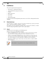
2.1 Safety Warnings
Prior to the installation, please review the safety warnings as follows:
For Nordic Countries Notices, see .Section E.1,“Nordic Countries Notices,” on page 75
For Safety Warnings in English, see Section E.2,“Installation Safety Warnings (English),” on
page 75.
For Safety Warnings in Hebrew, see Section E.3, “(תירבע) הנקתהב תוחיטב תורהזא,” on page 78.
For Safety Warnings in Chinese, see page 82.
For Safety Warnings in French, see Section E.5, “Avertissements de sécurité pour l'installation
(French),” on page 85.
For Safety Warnings in German, Section E.6, “Installation Sicherheitshinweise(German),” on
page 88.
For Safety Warnings in Spanish, see Section E.7, “Advertencias de seguridad de instalación
(Spanish),” on page 92.
For Safety Warnings in Russian, see Section E.8, “Предупреждения по технике безопасности
при установке (Russian),” on page 95.
For Safety Warnings in Romanian, see Section E.9, “Avertismente privind siguranţa la instalare
(Romanian),” on page 98.
For Safety Warnings in Croatian, see Section E.10, “Sigurnosna upozorenja za instaliranje (Croa-
tian),” on page 102.
The rack mounting holes conform to the EIA-310 standard for 19-inch racks. Take
precautions to guarantee proper ventilation in order to maintain good airflow at ambi
-
ent temperature.

Installation
Mellanox Technologies
18
For Safety Warnings in Italian, see Section E.11, “Avvertenze di sicurezza per l’installazione
(italiano),” on page 105.
For Safety Warnings in Turkish see Section E.12, “Montaj Güvenlik Uyarıları (Türkçe),” on
page 109.
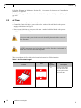
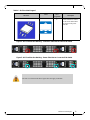
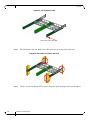
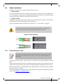
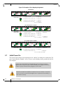
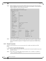
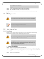
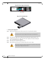
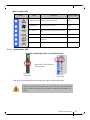
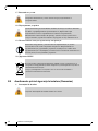
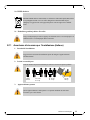
2.2 Air Flow
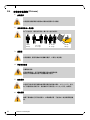
Mellanox systems are offered with two air flow patterns:
• Connector (front) side inlet to power side outlet - marked with red labels on the power
supply side as shown in
Figure 2.
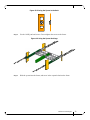
• Power (rear) side inlet to connector side outlet - marked with blue labels on the power
supply side as shown in
Figure 3.
Table 6 provides an air flow label color legend and respective OPN designations,
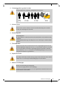
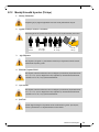
All servers and systems in the same rack should be planned with the same air-
flow direction.
All FRU components need to have the same air flow direction. A mismatch in
the air flow will affect the heat dissipation.
Table 6 - Air Flow Label Legend
Direction
Label OPN
Designation
Description
R Connector side inlet to
power side outlet. Red
labels are placed on the
power inlet side.

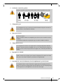
Mellanox Technologies
19
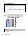
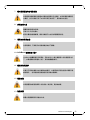
Figure 2: Air Flow Direction Marking - Connector Side Inlet to Power Side Outlet
Figure 3: Air Flow Direction Marking - Power Side Inlet to Connector Side Outlet
F Power side inlet to connec-
tor side outlet. Blue labels
are placed on the power
inlet side.
The rear view shown in the above figures does not apply to SX6012.
Table 6 - Air Flow Label Legend
Direction
Label OPN
Designation
Description
OK
!
!
OK
OK
!
!
OK
I2C
OK
!
!
OK
OK
!
!
OK
I2C

Installation
Mellanox Technologies
20
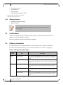
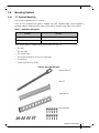
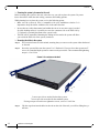
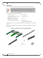
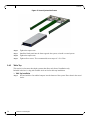
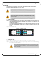
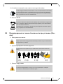
2.3 Package Contents
Before installing your new system, unpack the system, and check, against the parts list below,
that all the parts have been sent. Check the parts for visible damage that may have occurred
during shipping.
The SX60XX package content is as follows:
• 1 – System
• 1 – Rail kit (not applicable for half-width systems)
• 1 or 2 (according to order)– Power cables – Type C13 to C14, length 183cm
• 1 – Harness DB9 to RJ-45 (applicable for managed systems only)
• 1 – Quick Start Guide
If anything is damaged or missing, contact your sales representative at support@mella-
nox.com.
Pagina se încarcă...
Pagina se încarcă...
Pagina se încarcă...
Pagina se încarcă...
Pagina se încarcă...
Pagina se încarcă...
Pagina se încarcă...
Pagina se încarcă...
Pagina se încarcă...
Pagina se încarcă...
Pagina se încarcă...
Pagina se încarcă...
Pagina se încarcă...
Pagina se încarcă...
Pagina se încarcă...
Pagina se încarcă...
Pagina se încarcă...
Pagina se încarcă...
Pagina se încarcă...
Pagina se încarcă...
Pagina se încarcă...
Pagina se încarcă...
Pagina se încarcă...
Pagina se încarcă...
Pagina se încarcă...
Pagina se încarcă...
Pagina se încarcă...
Pagina se încarcă...
Pagina se încarcă...
Pagina se încarcă...
Pagina se încarcă...
Pagina se încarcă...
Pagina se încarcă...
Pagina se încarcă...
Pagina se încarcă...
Pagina se încarcă...
Pagina se încarcă...
Pagina se încarcă...
Pagina se încarcă...
Pagina se încarcă...
Pagina se încarcă...
Pagina se încarcă...
Pagina se încarcă...
Pagina se încarcă...
Pagina se încarcă...
Pagina se încarcă...
Pagina se încarcă...
Pagina se încarcă...
Pagina se încarcă...
Pagina se încarcă...
Pagina se încarcă...
Pagina se încarcă...
Pagina se încarcă...
Pagina se încarcă...
Pagina se încarcă...
Pagina se încarcă...
Pagina se încarcă...
Pagina se încarcă...
Pagina se încarcă...
Pagina se încarcă...
Pagina se încarcă...
Pagina se încarcă...
Pagina se încarcă...
Pagina se încarcă...
Pagina se încarcă...
Pagina se încarcă...
Pagina se încarcă...
Pagina se încarcă...
Pagina se încarcă...
Pagina se încarcă...
Pagina se încarcă...
Pagina se încarcă...
Pagina se încarcă...
Pagina se încarcă...
Pagina se încarcă...
Pagina se încarcă...
Pagina se încarcă...
Pagina se încarcă...
Pagina se încarcă...
Pagina se încarcă...
Pagina se încarcă...
Pagina se încarcă...
Pagina se încarcă...
Pagina se încarcă...
Pagina se încarcă...
Pagina se încarcă...
Pagina se încarcă...
Pagina se încarcă...
Pagina se încarcă...
Pagina se încarcă...
Pagina se încarcă...
Pagina se încarcă...
-
 1
1
-
 2
2
-
 3
3
-
 4
4
-
 5
5
-
 6
6
-
 7
7
-
 8
8
-
 9
9
-
 10
10
-
 11
11
-
 12
12
-
 13
13
-
 14
14
-
 15
15
-
 16
16
-
 17
17
-
 18
18
-
 19
19
-
 20
20
-
 21
21
-
 22
22
-
 23
23
-
 24
24
-
 25
25
-
 26
26
-
 27
27
-
 28
28
-
 29
29
-
 30
30
-
 31
31
-
 32
32
-
 33
33
-
 34
34
-
 35
35
-
 36
36
-
 37
37
-
 38
38
-
 39
39
-
 40
40
-
 41
41
-
 42
42
-
 43
43
-
 44
44
-
 45
45
-
 46
46
-
 47
47
-
 48
48
-
 49
49
-
 50
50
-
 51
51
-
 52
52
-
 53
53
-
 54
54
-
 55
55
-
 56
56
-
 57
57
-
 58
58
-
 59
59
-
 60
60
-
 61
61
-
 62
62
-
 63
63
-
 64
64
-
 65
65
-
 66
66
-
 67
67
-
 68
68
-
 69
69
-
 70
70
-
 71
71
-
 72
72
-
 73
73
-
 74
74
-
 75
75
-
 76
76
-
 77
77
-
 78
78
-
 79
79
-
 80
80
-
 81
81
-
 82
82
-
 83
83
-
 84
84
-
 85
85
-
 86
86
-
 87
87
-
 88
88
-
 89
89
-
 90
90
-
 91
91
-
 92
92
-
 93
93
-
 94
94
-
 95
95
-
 96
96
-
 97
97
-
 98
98
-
 99
99
-
 100
100
-
 101
101
-
 102
102
-
 103
103
-
 104
104
-
 105
105
-
 106
106
-
 107
107
-
 108
108
-
 109
109
-
 110
110
-
 111
111
-
 112
112


Mellanox Technologies SX6025 Manual de utilizare
- Tip
- Manual de utilizare
în alte limbi
Lucrări înrudite
-
Mellanox Technologies MSX1024B-2BFS Manual de utilizare
-
-
-
-
-
-
-
-
-