
Mellanox Technologieswww.mellanox.com
Mellanox SwitchX®-2
1U Switch Systems
Hardware User Manual
Model: SX67X0 and SX6710G
Rev 2.0

Mellanox Technologies
350 Oakmead Parkway Suite 100
Sunnyvale, CA 94085
U.S.A.
www.mellanox.com
Tel: (408) 970-3400
Fax: (408) 970-3403
© Copyright 2018. Mellanox Technologies Ltd . All Rights Reserved .
Mellanox®, Mellanox logo, Accelio®, BridgeX®, CloudX logo, CompustorX®, Connect-IB®, ConnectX®,
CoolBox®, CORE-Direct®, EZchip®, EZchip logo, EZappliance®, EZdesign®, EZdriver®, EZsystem®,
GPUDirect®, InfiniHost®, InfiniBridge®, InfiniScale®, Kotura®, Kotura logo, Mellanox CloudRack® , Mellanox
CloudXMellanox® , Mellanox Federal Systems® , Mellanox HostDirect® , Mellanox Multi-Host® , Mellanox Open
Ethernet®, Mellanox OpenCloud® , Mellanox OpenCloud Logo® , Mellanox PeerDirect® , Mellanox ScalableHPC® ,
Mellanox StorageX® , Mellanox TuneX® , Mellanox Connect Accelerate Outperform logo , Mellanox Virtual Modular
Switch®, MetroDX®, MetroX®, MLNX-OS®, NP-1c®, NP-2®, NP-3®, NPS®, Open Ethernet logo, PhyX®,
PlatformX®, PSIPHY®, SiPhy®, StoreX®, SwitchX®, Tilera®, Tilera logo, TestX®, TuneX®, The Generation of
Open Ethernet logo, UFM®, Unbreakable Link® , Virtual Protocol Interconnect® , Voltaire® and Voltaire logo are
registered trademarks of Mellanox Technologies , Ltd.
All other trademarks are property of their respective owners .
For the most updated list of Mellanox trademarks, visit http://www.mellanox.com/page/trademarks
NOTE:
THIS HARDWARE, SOFTWARE OR TEST SUITE PRODUCT (“PRODUCT (S)”) AND ITS RELATED
DOCUMENTATION ARE PROVIDED BY MELLANOX TECHNOLOGIES “AS-IS” WITH ALL FAULTS OF ANY
KIND AND SOLELY FOR THE PURPOSE OF AIDING THE CUSTOMER IN TESTING APPLICATIONS THAT
USE THE PRODUCTS IN DESIGNATED SOLUTIONS. THE CUSTOMER'S MANUFACTURING TEST
ENVIRONMENT HAS NOT MET THE STANDARDS SET BY MELLANOX TECHNOLOGIES TO FULLY
QUALIFY THE PRODUCT(S) AND/OR THE SYSTEM USING IT. THEREFORE, MELLANOX TECHNOLOGIES
CANNOT AND DOES NOT GUARANTEE OR WARRANT THAT THE PRODUCTS WILL OPERATE WITH THE
HIGHEST QUALITY. ANY EXPRESS OR IMPLIED WARRANTIES, INCLUDING, BUT NOT LIMITED TO, THE
IMPLIED WARRANTIES OF MERCHANTABILITY, FITNESS FOR A PARTICULAR PURPOSE AND
NONINFRINGEMENT ARE DISCLAIMED. IN NO EVENT SHALL MELLANOX BE LIABLE TO CUSTOMER OR
ANY THIRD PARTIES FOR ANY DIRECT, INDIRECT, SPECIAL, EXEMPLARY, OR CONSEQUENTIAL
DAMAGES OF ANY KIND (INCLUDING , BUT NOT LIMITED TO, PAYMENT FOR PROCUREMENT OF
SUBSTITUTE GOODS OR SERVICES; LOSS OF USE, DATA, OR PROFITS; OR BUSINESS INTERRUPTION)
HOWEVER CAUSED AND ON ANY THEORY OF LIABILITY, WHETHER IN CONTRACT , STRICT LIABILITY,
OR TORT (INCLUDING NEGLIGENCE OR OTHERWISE) ARISING IN ANY WAY FROM THE USE OF THE
PRODUCT (S) AND RELATED DOCUMENTATION EVEN IF ADVISED OF THE POSSIBILITY OF SUCH
DAMAGE.
Doc #: MLNX-15-4241
2Mellanox Technologies

Rev 1.9 3Mellanox Technologies
Table of Contents
Chapter 1 Introduction to Mellanox SX67X0/SX6710G Systems . . . . . . . . . . 11
1.1 Overview . . . . . . . . . . . . . . . . . . . . . . . . . . . . . . . . . . . . . . . . . . . . . . . . . . . . 11
1.2 Speed and Switching . . . . . . . . . . . . . . . . . . . . . . . . . . . . . . . . . . . . . . . . . . 12
1.3 Management Interfaces, PSUs and Fans . . . . . . . . . . . . . . . . . . . . . . . . . . 12
1.4 Features. . . . . . . . . . . . . . . . . . . . . . . . . . . . . . . . . . . . . . . . . . . . . . . . . . . . . 12
1.5 Certifications . . . . . . . . . . . . . . . . . . . . . . . . . . . . . . . . . . . . . . . . . . . . . . . . . 12
1.6 Ordering Information . . . . . . . . . . . . . . . . . . . . . . . . . . . . . . . . . . . . . . . . . . 13
Chapter 2 Installation . . . . . . . . . . . . . . . . . . . . . . . . . . . . . . . . . . . . . . . . . . . . 14
2.1 Safety Warnings . . . . . . . . . . . . . . . . . . . . . . . . . . . . . . . . . . . . . . . . . . . . . . 14
2.2 System Installation and Initialization . . . . . . . . . . . . . . . . . . . . . . . . . . . . . 15
2.3 Air Flow . . . . . . . . . . . . . . . . . . . . . . . . . . . . . . . . . . . . . . . . . . . . . . . . . . . . . 15
2.4 Package Contents . . . . . . . . . . . . . . . . . . . . . . . . . . . . . . . . . . . . . . . . . . . . . 16
2.5 Battery Backup Unit (BBU) Installation for SX6720 . . . . . . . . . . . . . . . . . . 18
2.5.1 Installing the Battery. . . . . . . . . . . . . . . . . . . . . . . . . . . . . . . . . . . . . . . . . . . 18
2.5.2 Extracting the Battery . . . . . . . . . . . . . . . . . . . . . . . . . . . . . . . . . . . . . . . . . . 19
2.6 Mounting Options . . . . . . . . . . . . . . . . . . . . . . . . . . . . . . . . . . . . . . . . . . . . 20
2.6.1 Static Rail Kit . . . . . . . . . . . . . . . . . . . . . . . . . . . . . . . . . . . . . . . . . . . . . . . . . 20
2.6.2 Telescopic Rail Kit . . . . . . . . . . . . . . . . . . . . . . . . . . . . . . . . . . . . . . . . . . . . . 25
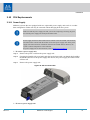
2.7 Cable Installation . . . . . . . . . . . . . . . . . . . . . . . . . . . . . . . . . . . . . . . . . . . . . 32
2.7.1 Breakout Cables and Adapters. . . . . . . . . . . . . . . . . . . . . . . . . . . . . . . . . . . 32
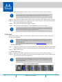
2.8 Initial Power On . . . . . . . . . . . . . . . . . . . . . . . . . . . . . . . . . . . . . . . . . . . . . . 34
2.9 System Bring-Up . . . . . . . . . . . . . . . . . . . . . . . . . . . . . . . . . . . . . . . . . . . . . . 35
2.9.1 Configuring Network Attributes . . . . . . . . . . . . . . . . . . . . . . . . . . . . . . . . . 35
2.10 FRU Replacements . . . . . . . . . . . . . . . . . . . . . . . . . . . . . . . . . . . . . . . . . . . . 41
2.10.1 Power Supply . . . . . . . . . . . . . . . . . . . . . . . . . . . . . . . . . . . . . . . . . . . . . . . . 41
2.10.2 Fans . . . . . . . . . . . . . . . . . . . . . . . . . . . . . . . . . . . . . . . . . . . . . . . . . . . . . . . . 42
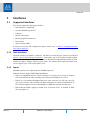
Chapter 3 Interfaces . . . . . . . . . . . . . . . . . . . . . . . . . . . . . . . . . . . . . . . . . . . . . 43
3.1 Supported Interfaces . . . . . . . . . . . . . . . . . . . . . . . . . . . . . . . . . . . . . . . . . . 43
3.1.1 Data Interfaces . . . . . . . . . . . . . . . . . . . . . . . . . . . . . . . . . . . . . . . . . . . . . . . 43
3.1.2 Speed . . . . . . . . . . . . . . . . . . . . . . . . . . . . . . . . . . . . . . . . . . . . . . . . . . . . . . . 43
3.1.3 RS232 (Console). . . . . . . . . . . . . . . . . . . . . . . . . . . . . . . . . . . . . . . . . . . . . . . 44
3.1.4 Management . . . . . . . . . . . . . . . . . . . . . . . . . . . . . . . . . . . . . . . . . . . . . . . . . 44
3.1.5 USB . . . . . . . . . . . . . . . . . . . . . . . . . . . . . . . . . . . . . . . . . . . . . . . . . . . . . . . . . 44
3.1.6 Reset Button . . . . . . . . . . . . . . . . . . . . . . . . . . . . . . . . . . . . . . . . . . . . . . . . . 44
3.1.7 Status and Port LEDs . . . . . . . . . . . . . . . . . . . . . . . . . . . . . . . . . . . . . . . . . . . 45
3.2 LEDs . . . . . . . . . . . . . . . . . . . . . . . . . . . . . . . . . . . . . . . . . . . . . . . . . . . . . . . . 45

4 Mellanox Technologies
3.2.1 LED Notifications . . . . . . . . . . . . . . . . . . . . . . . . . . . . . . . . . . . . . . . . . . . . . . 45
3.3 Inventory Information . . . . . . . . . . . . . . . . . . . . . . . . . . . . . . . . . . . . . . . . . 50
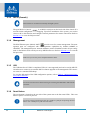
Chapter 4 Software Management . . . . . . . . . . . . . . . . . . . . . . . . . . . . . . . . . . 52
4.1 InfiniBand Subnet Manager . . . . . . . . . . . . . . . . . . . . . . . . . . . . . . . . . . . . . 52
4.2 Fabric Inspector (Diagnostics) . . . . . . . . . . . . . . . . . . . . . . . . . . . . . . . . . . . 52
4.3 Upgrading Software (on Managed Systems) . . . . . . . . . . . . . . . . . . . . . . . 53
4.3.1 MLNX-OS Software Upgrade . . . . . . . . . . . . . . . . . . . . . . . . . . . . . . . . . . . . 53
4.3.2 Switch Firmware Update . . . . . . . . . . . . . . . . . . . . . . . . . . . . . . . . . . . . . . . 53
Chapter 5 Troubleshooting . . . . . . . . . . . . . . . . . . . . . . . . . . . . . . . . . . . . . . . . 54
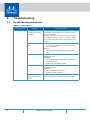
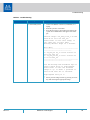
5.1 Troubleshooting Instructions. . . . . . . . . . . . . . . . . . . . . . . . . . . . . . . . . . . . 54
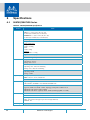
Chapter 6 Specifications . . . . . . . . . . . . . . . . . . . . . . . . . . . . . . . . . . . . . . . . . . 56
6.1 SX67X0/SX6710G Series . . . . . . . . . . . . . . . . . . . . . . . . . . . . . . . . . . . . . . . . 56

Rev 1.9 5Mellanox Technologies
List of Tables
Table 1: Revision History Table . . . . . . . . . . . . . . . . . . . . . . . . . . . . . . . . . . . . . . . . . . . . . . . . . 8
Table 2: References . . . . . . . . . . . . . . . . . . . . . . . . . . . . . . . . . . . . . . . . . . . . . . . . . . . . . . . . . . 9
Table 3: Speed and Switching Capabilities . . . . . . . . . . . . . . . . . . . . . . . . . . . . . . . . . . . . . . . 12
Table 4: Management Interfaces, PSUs and Fans . . . . . . . . . . . . . . . . . . . . . . . . . . . . . . . . . 12
Table 5: Ordering Part Numbers (OPNs) . . . . . . . . . . . . . . . . . . . . . . . . . . . . . . . . . . . . . . . . 13
Table 6: Air Flow Color Legend . . . . . . . . . . . . . . . . . . . . . . . . . . . . . . . . . . . . . . . . . . . . . . . . 16
Table 7: Installation Kit . . . . . . . . . . . . . . . . . . . . . . . . . . . . . . . . . . . . . . . . . . . . . . . . . . . . . . 20
Table 8: Installation Kit . . . . . . . . . . . . . . . . . . . . . . . . . . . . . . . . . . . . . . . . . . . . . . . . . . . . . . 26
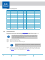
Table 9: Port Splitting Options . . . . . . . . . . . . . . . . . . . . . . . . . . . . . . . . . . . . . . . . . . . . . . . . 33
Table 10: Serial Terminal Program Configuration . . . . . . . . . . . . . . . . . . . . . . . . . . . . . . . . . . 36
Table 11: Configuration Wizard Session . . . . . . . . . . . . . . . . . . . . . . . . . . . . . . . . . . . . . . . . . . 36
Table 12: Configuration Wizard Session - Static IP Configuration . . . . . . . . . . . . . . . . . . . . . 38
Table 13: LEDs Symbols . . . . . . . . . . . . . . . . . . . . . . . . . . . . . . . . . . . . . . . . . . . . . . . . . . . . . . . 45
Table 14: System Status LED Assignments . . . . . . . . . . . . . . . . . . . . . . . . . . . . . . . . . . . . . . . . 46
Table 15: Fan Status Rear LED Assignments (One LED per Fan) . . . . . . . . . . . . . . . . . . . . . . . 47
Table 16: Power Supply Unit Status Front LED Assignments . . . . . . . . . . . . . . . . . . . . . . . . . 48
Table 17: Power Supply Unit Status Rear LED Assignments . . . . . . . . . . . . . . . . . . . . . . . . . .48
Table 18: Bad Port LED Assignments . . . . . . . . . . . . . . . . . . . . . . . . . . . . . . . . . . . . . . . . . . . . 49
Table 19: BBU LED Assignments . . . . . . . . . . . . . . . . . . . . . . . . . . . . . . . . . . . . . . . . . . . . . . . . 49
Table 20: Port LEDs in InfiniBand System Mode . . . . . . . . . . . . . . . . . . . . . . . . . . . . . . . . . . . 50
Table 21: Troubleshooting. . . . . . . . . . . . . . . . . . . . . . . . . . . . . . . . . . . . . . . . . . . . . . . . . . . . . 54
Table 22: SX67X0/SX6710G Specifications . . . . . . . . . . . . . . . . . . . . . . . . . . . . . . . . . . . . . . . . 56
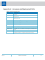
Table 23: OPNs for Replacement Parts. . . . . . . . . . . . . . . . . . . . . . . . . . . . . . . . . . . . . . . . . . . 57
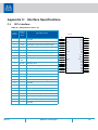
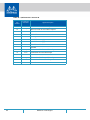
Table 24: QSFP Interface Pins 1-23 . . . . . . . . . . . . . . . . . . . . . . . . . . . . . . . . . . . . . . . . . . . . . . 59
Table 25: QSFP Interface Pins 24-38 . . . . . . . . . . . . . . . . . . . . . . . . . . . . . . . . . . . . . . . . . . . . . 60

6 Mellanox Technologies
List of Figures
Figure 1: SX67X0/SX6710G Front Side View . . . . . . . . . . . . . . . . . . . . . . . . . . . . . . . . . . . . . . . . . . . . 12
Figure 2: SX67X0/SX6710G Rear Side View . . . . . . . . . . . . . . . . . . . . . . . . . . . . . . . . . . . . . . . . . . . . . 12
Figure 3: Air Flow Direction Marking - Power Side Inlet to Connector Side Outlet . . . . . . . . . . . . . 16
Figure 4: Air Flow Direction Marking - Connector Side Inlet to Power Side Outlet . . . . . . . . . . . . . 16
Figure 5: Unlocking the Latches and Extracting the PSU . . . . . . . . . . . . . . . . . . . . . . . . . . . . . . . . . . 19
Figure 6: BBU Location . . . . . . . . . . . . . . . . . . . . . . . . . . . . . . . . . . . . . . . . . . . . . . . . . . . . . . . . . . . . . 19
Figure 7: BBU Insertion (Left) and Extraction (Right) . . . . . . . . . . . . . . . . . . . . . . . . . . . . . . . . . . . . . 20
Figure 8: Rack Rail Kit Parts . . . . . . . . . . . . . . . . . . . . . . . . . . . . . . . . . . . . . . . . . . . . . . . . . . . . . . . . . 21
Figure 9: Installation Options . . . . . . . . . . . . . . . . . . . . . . . . . . . . . . . . . . . . . . . . . . . . . . . . . . . . . . . . 22
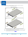
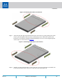
Figure 10: Attaching the Rails to the Chassis . . . . . . . . . . . . . . . . . . . . . . . . . . . . . . . . . . . . . . . . . . . . 23
Figure 11: Attaching the Brackets to the Chassis . . . . . . . . . . . . . . . . . . . . . . . . . . . . . . . . . . . . . . . . . 23
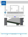
Figure 12: Installing the Cage Nuts . . . . . . . . . . . . . . . . . . . . . . . . . . . . . . . . . . . . . . . . . . . . . . . . . . . .24
Figure 13: Attaching the Brackets to the Rack . . . . . . . . . . . . . . . . . . . . . . . . . . . . . . . . . . . . . . . . . . . 24
Figure 14: Sliding the Blades in the Rails . . . . . . . . . . . . . . . . . . . . . . . . . . . . . . . . . . . . . . . . . . . . . . . . 25
Figure 15: Rack Rail Kit Parts . . . . . . . . . . . . . . . . . . . . . . . . . . . . . . . . . . . . . . . . . . . . . . . . . . . . . . . . . 27
Figure 16: Rails Separation . . . . . . . . . . . . . . . . . . . . . . . . . . . . . . . . . . . . . . . . . . . . . . . . . . . . . . . . . . . 28
Figure 17: Installing the Cage Nuts . . . . . . . . . . . . . . . . . . . . . . . . . . . . . . . . . . . . . . . . . . . . . . . . . . . .28
Figure 18: Mounting the Outer Rails into the Rack . . . . . . . . . . . . . . . . . . . . . . . . . . . . . . . . . . . . . . . 29
Figure 19: Attaching the Inner Rails to the Chassis . . . . . . . . . . . . . . . . . . . . . . . . . . . . . . . . . . . . . . . 29
Figure 20: Securing the Chassis in the Inner Rails . . . . . . . . . . . . . . . . . . . . . . . . . . . . . . . . . . . . . . . . . 29
Figure 21: Sliding the Switch into the Rack . . . . . . . . . . . . . . . . . . . . . . . . . . . . . . . . . . . . . . . . . . . . . . 30
Figure 22: Pulling the Unit Outwards . . . . . . . . . . . . . . . . . . . . . . . . . . . . . . . . . . . . . . . . . . . . . . . . . . . 31
Figure 23: Locking Mechanism . . . . . . . . . . . . . . . . . . . . . . . . . . . . . . . . . . . . . . . . . . . . . . . . . . . . . . . .31
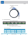
Figure 24: Cable Orientation . . . . . . . . . . . . . . . . . . . . . . . . . . . . . . . . . . . . . . . . . . . . . . . . . . . . . . . . . 32
Figure 25: Breakout or Fanout Cable . . . . . . . . . . . . . . . . . . . . . . . . . . . . . . . . . . . . . . . . . . . . . . . . . . . 33
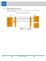
Figure 26: SX67X0 Splitting Options . . . . . . . . . . . . . . . . . . . . . . . . . . . . . . . . . . . . . . . . . . . . . . . . . . . .33
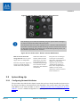
Figure 27: System Status LEDs 5 Minutes After Power On . . . . . . . . . . . . . . . . . . . . . . . . . . . . . . . . . 35
Figure 28: Two Power Inlets - Electric Caution Notifications . . . . . . . . . . . . . . . . . . . . . . . . . . . . . . . . 35
Figure 29: PS Unit Pulled Out . . . . . . . . . . . . . . . . . . . . . . . . . . . . . . . . . . . . . . . . . . . . . . . . . . . . . . . . . 41
Figure 30: Fan Module Latches . . . . . . . . . . . . . . . . . . . . . . . . . . . . . . . . . . . . . . . . . . . . . . . . . . . . . . .42
Figure 31: System Status LEDs - Front and Rear Sides . . . . . . . . . . . . . . . . . . . . . . . . . . . . . . . . . . . . . 46
Figure 32: Fan Status LED- Front and Rear Sides . . . . . . . . . . . . . . . . . . . . . . . . . . . . . . . . . . . . . . . . . 46
Figure 33: Power Status LED . . . . . . . . . . . . . . . . . . . . . . . . . . . . . . . . . . . . . . . . . . . . . . . . . . . . . . . . . . 47
Figure 34: Rear Side Panel . . . . . . . . . . . . . . . . . . . . . . . . . . . . . . . . . . . . . . . . . . . . . . . . . . . . . . . . . . . 47
Figure 35: Port LEDs . . . . . . . . . . . . . . . . . . . . . . . . . . . . . . . . . . . . . . . . . . . . . . . . . . . . . . . . . . . . . . . . 49

Rev 2.0 7Mellanox Technologies
Figure 36: Pull-out Tab . . . . . . . . . . . . . . . . . . . . . . . . . . . . . . . . . . . . . . . . . . . . . . . . . . . . . . . . . . . . . . 51
Figure 37: Rear View of Module With Pin Placement . . . . . . . . . . . . . . . . . . . . . . . . . . . . . . . . . . . . . 61
Figure 38: RJ45 to DB9 Harness Pinout . . . . . . . . . . . . . . . . . . . . . . . . . . . . . . . . . . . . . . . . . . . . . . . . . 63

8 Mellanox Technologies
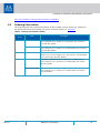
Revision History
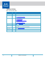
Table 1 - Revision History Table
Date Revision Description
February 2018 2.0 Added SX6710G
January 2018 1.9 Added Taiwan RoHS table to the “Safety Warnings (Multiple Languages)”.
February 2017 1.8 Updated:
• “Unit Identification LED”
February 2017 1.7 Updated:
• “Data Interfaces”
• “Specifications”
• “RJ45 to DB9 Harness Pinout”
Added:
• “BBU LED Assignments”
October 2015 1.5 • Edited “Installation”
August 2015 1.4 Minor fixes
May 2015 1.3 Added Hebrew safety warnings
Added BBU safety warnings in all languages
April 2015 1.2 Added “Telescopic Rail Kit”
January 2015 1.1 Minor formatting edits
January 2015 1.0 Initial release of the first edition

9Mellanox Technologies
About this Manual
This manual describes the installation and basic use of the Mellanox InfiniBand systems.
Intended Audience
This manual is intended for IT managers and system administrators.
References
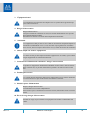
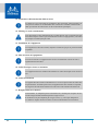
Conventions
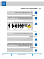
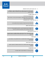
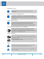
The following icons are used throughout this document to indicate information that is important
to the user.
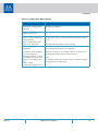
Table 2 - References
Document Description
MLNX-OS® User Man-
ual
This document contains information regarding the configuration and man-
agement of the MLNX-OS software. See http://www.mellanox.com/page/
mlnx_os.
This icon makes recommendations to the user.
This icon indicates information that is helpful to the user.

10 Mellanox Technologies
This icon indicates a situation that can potentially cause damage to hardware or
software.
This icon indicates a situation that can potentially cause personal injury.
This icon indicates a situation that can potentially cause personal injury.

Introduction to Mellanox SX67X0/SX6710G Systems
Rev 2.0
11Mellanox Technologies
1 Introduction to Mellanox SX67X0/SX6710G Systems
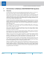
1.1 Overview
The SX67X0/SX6710G systems provide the highest performing fabric solution in a 1U form fac-
tor by delivering up to 4Tb/s of non-blocking bandwidth with 200ns port-to-port latency.
These systems are the industry's most cost-effective building blocks for embedded systems and
storage with a need for low port density systems. Whether looking at price-to-performance or
energy-to-performance, these systems offer superior performance, power and space, reducing
capital and operating expenses and providing the best return-on-investment. The systems are an
ideal choice for smaller departmental or back-end clustering uses with high-performance needs,
such as storage, data base and GPGPU clusters.
Powerful servers combined with high-performance storage and applications that use increasingly
complex computations are causing data bandwidth requirements to spiral upward. As servers are
deployed with next generation processors, High-Performance Computing (HPC) environments
and Enterprise Data Centers (EDC) need every last bit of bandwidth delivered with Mellanox’s
FDR InfiniBand systems.
Built with Mellanox’s sixth generation SwitchX®-2 InfiniBand FDR 56Gb/s system device,
these standalone systems are an ideal choice for top-of-rack leaf connectivity or for building
small to extremely large sized clusters.
These systems enable efficient computing with features such as static routing, adaptive routing,
and advanced congestion management. These features ensure the maximum effective fabric
bandwidth by eliminating congestion.
The managed systems comes with an onboard subnet manager, enabling simple, out-of-the-box
fabric bring-up for up to 2048 nodes. MLNX-OS® software delivers complete chassis manage
-
ment of firmware, power supplies, fans, ports and other interfaces.
Mellanox’s edge systems can also be coupled with Mellanox’s Unified Fabric Manager (UFM®)
software for managing scale-out InfiniBand computing environments. UFM enables data center
operators to efficiently provision, monitor and operate the modern data center fabric. UFM
boosts application performance and ensures that the fabric is up and running at all times.
InfiniBand systems come as internally or externally managed. Internally managed systems come
with a CPU that runs the management software (MLNX-OS®) and management ports which are
used to transfer management traffic into the system. Externally managed systems come without
the CPU and management ports and are managed using firmware tools.
Mellanox's InfiniBand to Ethernet gateway, built with Mellanox's SwitchX®-2 based systems,
provides the most cost-effective, high-performance solution for data center unified connectivity
solutions. Mellanox's gateways enable data centers to operate at up to 56Gb/s network speeds
while seamlessly connecting to 1, 10 and 40GbE networks with low latency (400ns). Existing
LAN infrastructures and management practices can be preserved, easing deployment and provid
-
ing significant return-on-investment.

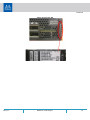
12 Mellanox Technologies
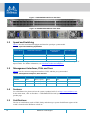
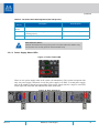
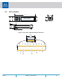
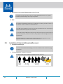
Figure 1: SX67X0/SX6710G Front Side View
Figure 2: SX67X0/SX6710G Rear Side View
1.2 Speed and Switching
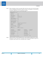
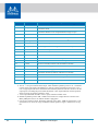
Table 3 describes maximum throughput and interface speed per system model.
*The system can support different interfaces and speed rates using QSFP+
to SFP+ adapters or
hybrid cables. For further information, see
“Breakout Cables and Adapters”.
1.3 Management Interfaces, PSUs and Fans
Table 4 lists the various management interfaces, PSUs and fans per system model.
1.4 Features
For a full feature list, please refer to the system’s product brief. Go to http://www.mellanox.com.
In the main menu, click on Products--> InfiniBand/VPI Switch Sys
tems, and select the desired
product page.
1.5 Certifications
The list of certifications (such as EMC, Safety and others) per system for different regions of the
world is located on the Mellanox website at:
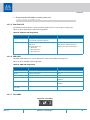
Table 3 - Speed and Switching Capabilities
System Model 10GbE SFP+ Interfaces*
40/56GbE QSFP+
Interfaces*
Max Throughput
SX6710 N/A 36 4.032Tb/s
SX6720* N/A 36 4.032Tb/s
SX6710G N/A 36 4.032Tb/s
Table 4 - Management Interfaces, PSUs and Fans
System Model USB MGT Console PSU Fan
SX6710 Rear Rear (2 ports) Rear Yes Yes
SX6720 Rear Rear (2 ports) Rear Yes Yes
SX6710G Rear Rear (2 ports) Rear Yes Yes

Introduction to Mellanox SX67X0/SX6710G Systems
Rev 2.0
13Mellanox Technologies
http://www.mellanox.com/page/environmental_compliance
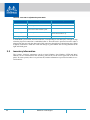
1.6 Ordering Information
The following table lists ordering information for the available systems. Please pay attention to
the airflow direction when ordering your system. For more details, see
“Air Flow”.
Table 5 - Ordering Part Numbers (OPNs)
System
Model
OPN Description
SX6710 MSX6710-FB2F2 SwitchX®-2 based FDR InfiniBand 1U Switch, 36 QSFP+ ports, 2
Power Supplies (AC), x86 dual core, short depth, rear to front air-
flow, Rail Kit, RoHS6
MSX6710-FS2F2 SwitchX®-2 based FDR InfiniBand 1U Switch, 36 QSFP+ ports, 2
Pow
er Suppli
es (AC), x86 dual core, standard depth, rear to front air-
flow, Rail Kit, RoHS6
SX6720 MSX6720-FS2F2 SwitchX®-2 based FDR InfiniBand 1U Switch BBU ready,36
Q
SFP+ ports, 2
Power Supplies (AC), x86 dual core, standard depth,
rear to front airflow, Rail Kit, RoHS6
SX6710G MSX6710G-FS2F2
SwitchX®-2 InfiniBand to Ethernet gateway, 36 QSFP+ ports, 2
Power Supplies (AC), x86 dual core, standard depth, C2P airflow,
Rail Kit, RoHS6
SwitchX®-2 InfiniBand to Ethernet gateway, 36 QSFP+ ports, 2
Power Supplies (AC), x86 dual core, standard depth, P2C airflow,
Rail Kit, RoHS6
MSX6710G-FS2R2

14 Mellanox Technologies
2 Installation
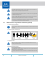
2.1 Safety Warnings
Prior to the installation, please review the safety warnings as follows:
• For Nordic Countries Notices, see Section E.1, “Nordic Countries Notices,” on page 65.
• For Safety Warnings in English, see Section E.2, “Installation Safety Warnings
(English),” on page 65.
• For Safety Warnings in Hebrew, see Section E.3, “הנקתהב תוחיטב תוארוה (Hebrew),” on
page 69.
• For Safety Warnings in Chinese, see Section 1 on page 72.
• For Safety Warnings in French, see Section 27, “Taiwan RoHS Declaration,” on page 78.
• For Safety Warnings in German, Section E.6, “Installation Sicherheitshinweise(Ger-
man),” on page 82.
• For Safety Warnings in Spanish, see Section E.7, “Advertencias de seguridad de insta-
lación (Spanish),” on page 86.
• For Safety Warnings in Russian, see Section E.8, “Предупреждения по технике
безопасности при установке (Russian),” on page 90.
• For Safety Warnings in Romanian, see Section E.9, “Avertismente privind siguranţa la
instalare (Romanian),” on page 94.
• For Safety Warnings in Croatian, see Section E.10, “Sigurnosna upozorenja za instali-
ranje (Croatian),” on page 98.
• For Safety Warnings in Italian, see Section E.11, “Avvertenze di sicurezza per
l’installazione (Italian),” on page 102.
• For Safety Warnings in Turkish see Section E.12, “Montaj Güvenlik Uyarıları (Turk-
ish),” on page 106.

Installation
Rev 2.0
15Mellanox Technologies
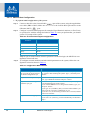
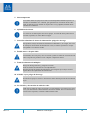
2.2 System Installation and Initialization
Installation and initialization of the system require attention to the normal mechanical, power,
and thermal precautions for rack-mounted equipment.
The installation procedure for the system involves the following phases:
1. Follow the safety warnings in Section 2.1.
2. Pay attention to the air flow consideration within the system and rack - refer to “Air Flow” on
page 15.
3. Make sure that none of the package contents is missing or damaged - see “Package Contents”
on page 16.
4. Mount the system into a rack enclosure - see “Mounting Options” on page 20.
5. Power on the system - refer to “Initial Power On” on page 34.
6. Perform system bring-up - see “System Bring-Up” on page 35.
7. [Optional]: FRU replacements are described in Section 2.10 on page 41.
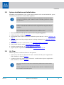
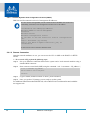
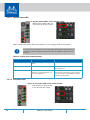
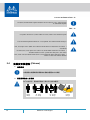
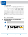
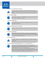
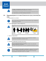
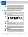
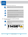
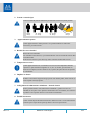
2.3 Air Flow
Mellanox systems are offered with two air flow patterns:
• Power (rear) side inlet to connector side outlet - marked with blue power supplies/fans-
FRUs’ handles, as shown in Figure 3.
• Connector (front) side inlet to power side outlet - marked with red power supplies/fans
FRUs’ handles, as shown in
Figure 4.
The rack mounting holes conform to the EIA-310 standard for 19-inch racks. Take
precautions to guarantee proper ventilation in order to maintain good airflow at ambi-
ent temperature.
Unless otherwise specified, Mellanox products are designed to work in an environ-
mentally controlled data center with low levels of gaseous and dust (particulate) con-
tamination.
The operation environment should meet severity level G1 as per ISA 71.04 for gas-
eous contamination and ISO 14644-1 class 8 for cleanliness level
All servers and systems in the same rack should be planned with the same airflow
direction.
All FRU components need to have the same air flow direction. A mismatch in the air
flow will affect the heat dissipation.

16 Mellanox Technologies
Table 6 provides an air flow color legend and respective OPN designation
Figure 3: Air Flow Direction Marking - Power Side Inlet to Connector Side Outlet
Figure 4: Air Flow Direction Marking - Connector Side Inlet to Power Side Outlet
2.4 Package Contents
Before installing your new system, unpack it and check against the parts list below that all the
parts have been sent. Check the parts for visible damage that may have occurred during shipping.
Table 6 - Air Flow Color Legend
Direction
OPN
Designation
Description
Ending with
“-R”
Connector side inlet to power side outlet.
Red latches are placed on the power inlet
side.
Ending with
“-F”
Power side inlet to connector side outlet.
Blue latches are placed on the power inlet
side.

Installation
Rev 2.0
17Mellanox Technologies
The SX67X0/SX6710G package content is as follows:
• 1 – System
• 1 – Rail kit
• 1 – Power cable for each power supply unit – Type C13-C14
• 1 – Harness DB9 to RJ-45
• 1 – Quick Start Guide
If anything is damaged or missing, contact your sales representative at support@mella-
nox.com.

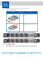
18 Mellanox Technologies
2.5 Battery Backup Unit (BBU) Installation for SX6720
A new Battery Back-up Unit (BBU) will be approximately 30% charged when you receive it. In
case of a power outage, only a fully charged BBU can supply power of up to 5 minutes to the sys
-
tem.
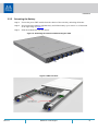
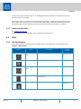
2.5.1 Installing the Battery
Step 1. Extract the power FRU module from the chassis of the switch by unlocking all latches
Step 2. Insert the BBU into the empty slot in the module by sliding it in and pushing the top end of
it down until it snaps into place, as illustrated in the left image of
Figure 7.
Step 3. Slide the module back into the chassis.
A BBU-compatible system is available by ordering an SX6720 system with an appro-
priate license.
If the BBU is deformed, leaking, corroded or visually damaged, replace it immediately
Do not use a BBU that was not provided by Mellanox Technologies
• The BBU maximum storage temperature is 25°C.
• The WebUI might show a fully charged battery, despite a possible 2-3% deviation.
Nevertheless, it is still safe to discharge the battery for up to 5 minutes.
• A BBU that has not been used for six months or longer past ts printed manufactur-
ing date is unusable.
• A BBU that is older than five years, according to the printed manufacturing date,
has reached its "end of life" state and may not provide enough energy to handle the
platform.
• In case the battery should be replaced, software notifications will appear on a
monthly basis, starting three months before EOL time.
Do not insert the battery unit into the switch during its discharge.

Installation
Rev 2.0
19Mellanox Technologies
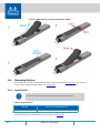
2.5.2 Extracting the Battery
Step 1. Extract the power FRU module from the chassis of the switch by unlocking all latches.
Step 2. Press both release buttons simultaneously and lift the battery up to remove it, as illustrated
in the right image of
Figure 7.
Step 3. Slide the module back into the chassis.
Figure 5: Unlocking the Latches and Extracting the PSU
Figure 6: BBU Location

20 Mellanox Technologies
Figure 7: BBU Insertion (Left) and Extraction (Right)
2.6 Mounting Options
By default, the systems are sold with the static rail kit described in Section 2.6.1. For the tele-
scopic rail kit installation instructions, see Section 2.6.2.
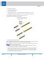
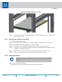
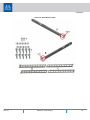
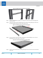
2.6.1 Static Rail Kit
The following parts are included in the static rail kit (see Figure 8):
At least two people are required to safely mount the system in the rack.
Table 7 - Installation Kit
Kit OPN Rack Size and Rack Depth Range
MTEF-KIT-A Short (17”-24”) or Standard (24”-34”)
Pagina se încarcă ...
Pagina se încarcă ...
Pagina se încarcă ...
Pagina se încarcă ...
Pagina se încarcă ...
Pagina se încarcă ...
Pagina se încarcă ...
Pagina se încarcă ...
Pagina se încarcă ...
Pagina se încarcă ...
Pagina se încarcă ...
Pagina se încarcă ...
Pagina se încarcă ...
Pagina se încarcă ...
Pagina se încarcă ...
Pagina se încarcă ...
Pagina se încarcă ...
Pagina se încarcă ...
Pagina se încarcă ...
Pagina se încarcă ...
Pagina se încarcă ...
Pagina se încarcă ...
Pagina se încarcă ...
Pagina se încarcă ...
Pagina se încarcă ...
Pagina se încarcă ...
Pagina se încarcă ...
Pagina se încarcă ...
Pagina se încarcă ...
Pagina se încarcă ...
Pagina se încarcă ...
Pagina se încarcă ...
Pagina se încarcă ...
Pagina se încarcă ...
Pagina se încarcă ...
Pagina se încarcă ...
Pagina se încarcă ...
Pagina se încarcă ...
Pagina se încarcă ...
Pagina se încarcă ...
Pagina se încarcă ...
Pagina se încarcă ...
Pagina se încarcă ...
Pagina se încarcă ...
Pagina se încarcă ...
Pagina se încarcă ...
Pagina se încarcă ...
Pagina se încarcă ...
Pagina se încarcă ...
Pagina se încarcă ...
Pagina se încarcă ...
Pagina se încarcă ...
Pagina se încarcă ...
Pagina se încarcă ...
Pagina se încarcă ...
Pagina se încarcă ...
Pagina se încarcă ...
Pagina se încarcă ...
Pagina se încarcă ...
Pagina se încarcă ...
Pagina se încarcă ...
Pagina se încarcă ...
Pagina se încarcă ...
Pagina se încarcă ...
Pagina se încarcă ...
Pagina se încarcă ...
Pagina se încarcă ...
Pagina se încarcă ...
Pagina se încarcă ...
Pagina se încarcă ...
Pagina se încarcă ...
Pagina se încarcă ...
Pagina se încarcă ...
Pagina se încarcă ...
Pagina se încarcă ...
Pagina se încarcă ...
Pagina se încarcă ...
Pagina se încarcă ...
Pagina se încarcă ...
Pagina se încarcă ...
Pagina se încarcă ...
Pagina se încarcă ...
Pagina se încarcă ...
Pagina se încarcă ...
Pagina se încarcă ...
Pagina se încarcă ...
Pagina se încarcă ...
Pagina se încarcă ...
Pagina se încarcă ...
Pagina se încarcă ...
-
 1
1
-
 2
2
-
 3
3
-
 4
4
-
 5
5
-
 6
6
-
 7
7
-
 8
8
-
 9
9
-
 10
10
-
 11
11
-
 12
12
-
 13
13
-
 14
14
-
 15
15
-
 16
16
-
 17
17
-
 18
18
-
 19
19
-
 20
20
-
 21
21
-
 22
22
-
 23
23
-
 24
24
-
 25
25
-
 26
26
-
 27
27
-
 28
28
-
 29
29
-
 30
30
-
 31
31
-
 32
32
-
 33
33
-
 34
34
-
 35
35
-
 36
36
-
 37
37
-
 38
38
-
 39
39
-
 40
40
-
 41
41
-
 42
42
-
 43
43
-
 44
44
-
 45
45
-
 46
46
-
 47
47
-
 48
48
-
 49
49
-
 50
50
-
 51
51
-
 52
52
-
 53
53
-
 54
54
-
 55
55
-
 56
56
-
 57
57
-
 58
58
-
 59
59
-
 60
60
-
 61
61
-
 62
62
-
 63
63
-
 64
64
-
 65
65
-
 66
66
-
 67
67
-
 68
68
-
 69
69
-
 70
70
-
 71
71
-
 72
72
-
 73
73
-
 74
74
-
 75
75
-
 76
76
-
 77
77
-
 78
78
-
 79
79
-
 80
80
-
 81
81
-
 82
82
-
 83
83
-
 84
84
-
 85
85
-
 86
86
-
 87
87
-
 88
88
-
 89
89
-
 90
90
-
 91
91
-
 92
92
-
 93
93
-
 94
94
-
 95
95
-
 96
96
-
 97
97
-
 98
98
-
 99
99
-
 100
100
-
 101
101
-
 102
102
-
 103
103
-
 104
104
-
 105
105
-
 106
106
-
 107
107
-
 108
108
-
 109
109
-
 110
110


Mellanox Technologies SX6710 Hardware User Manual
- Tip
- Hardware User Manual
în alte limbi
- English: Mellanox Technologies SX6710
- italiano: Mellanox Technologies SX6710
Lucrări conexe
-
Mellanox Technologies SX6730 Hardware User Manual
-
-
-
-
-
-
-
-
-