
www.mellanox.com
Mellanox SX67X0 1U Switch Systems Hardware
User Manual
Rev. 1.0

Mellanox Technologies
350 Oakmead Parkway Suite 100
Sunnyvale, CA 94085
U.S.A.
www.mellanox.com
Tel: (408) 970-3400
Fax: (408) 970-3403
Mellanox Technologies, Ltd.
Beit Mellanox
PO Box 586 Yokneam 20692
Israel
www.mellanox.com
Tel: +972 (0)74 723 7200
Fax: +972 (0)4 959 3245
© Copyright 2014. Mellanox Technologies. All Rights Reserved.
Mellanox®, Mellanox logo, BridgeX®, ConnectX®, CORE-Direct®, InfiniBridge®, InfiniHost®, InfiniScale®,
MLNX-OS®, PhyX®, SwitchX®, UFM®, Virtual Protocol Interconnect® and Voltaire® are registered trademarks of
Mellanox Technologies, Ltd.
Connect-IB™, ExtendX™, FabricIT™, Mellanox Open Ethernet™, Mellanox Virtual Modular Switch™, MetroX™,
MetroDX™, ScalableHPC™, Unbreakable-Link™ are trademarks of Mellanox Technologies, Ltd.
All other trademarks are property of their respective owners.
NOTE:
THIS HARDWARE, SOFTWARE OR TEST SUITE PRODUCT (“PRODUCT(S)”) AND ITS RELATED
DOCUMENTATION ARE PROVIDED BY MELLANOX TECHNOLOGIES “AS-IS” WITH ALL FAULTS OF ANY
KIND AND SOLELY FOR THE PURPOSE OF AIDING THE CUSTOMER IN TESTING APPLICATIONS THAT USE
THE PRODUCTS IN DESIGNATED SOLUTIONS. THE CUSTOMER'S MANUFACTURING TEST ENVIRONMENT
HAS NOT MET THE STANDARDS SET BY MELLANOX TECHNOLOGIES TO FULLY QUALIFY THE
PRODUCTO(S) AND/OR THE SYSTEM USING IT. THEREFORE, MELLANOX TECHNOLOGIES CANNOT AND
DOES NOT GUARANTEE OR WARRANT THAT THE PRODUCTS WILL OPERATE WITH THE HIGHEST
QUALITY. ANY EXPRESS OR IMPLIED WARRANTIES, INCLUDING, BUT NOT LIMITED TO, THE IMPLIED
WARRANTIES OF MERCHANTABILITY, FITNESS FOR A PARTICULAR PURPOSE AND NONINFRINGEMENT
ARE DISCLAIMED. IN NO EVENT SHALL MELLANOX BE LIABLE TO CUSTOMER OR ANY THIRD PARTIES
FOR ANY DIRECT, INDIRECT, SPECIAL, EXEMPLARY, OR CONSEQUENTIAL DAMAGES OF ANY KIND
(INCLUDING, BUT NOT LIMITED TO, PAYMENT FOR PROCUREMENT OF SUBSTITUTE GOODS OR SERVICES;
LOSS OF USE, DATA, OR PROFITS; OR BUSINESS INTERRUPTION) HOWEVER CAUSED AND ON ANY
THEORY OF LIABILITY, WHETHER IN CONTRACT, STRICT LIABILITY, OR TORT (INCLUDING NEGLIGENCE
OR OTHERWISE) ARISING IN ANY WAY FROM THE USE OF THE PRODUCT(S) AND RELATED
DOCUMENTATION EVEN IF ADVISED OF THE POSSIBILITY OF SUCH DAMAGE.
Document Number: MLNX-15-4241
Mellanox Technologies
2

Mellanox Technologies
1
Table of Contents
Revision History . . . . . . . . . . . . . . . . . . . . . . . . . . . . . . . . . . . . . . . . . . . . . . . . . . . . . . . . . . . 2
About this Manual . . . . . . . . . . . . . . . . . . . . . . . . . . . . . . . . . . . . . . . . . . . . . . . . . . . . . . . . . 3
Chapter 1 Introduction to Mellanox SX67X0 Systems. . . . . . . . . . . . . . . . . . . . . . . . . . . 4
1.1 Overview . . . . . . . . . . . . . . . . . . . . . . . . . . . . . . . . . . . . . . . . . . . . . . . . . . . . . . . . 4
1.2 Speed and Switching . . . . . . . . . . . . . . . . . . . . . . . . . . . . . . . . . . . . . . . . . . . . . . . 5
1.3 Management Interfaces and FRUs. . . . . . . . . . . . . . . . . . . . . . . . . . . . . . . . . . . . . 5
1.4 Features . . . . . . . . . . . . . . . . . . . . . . . . . . . . . . . . . . . . . . . . . . . . . . . . . . . . . . . . . 5
1.5 Certifications . . . . . . . . . . . . . . . . . . . . . . . . . . . . . . . . . . . . . . . . . . . . . . . . . . . . . 6
1.6 Ordering Information. . . . . . . . . . . . . . . . . . . . . . . . . . . . . . . . . . . . . . . . . . . . . . . 6
Chapter 2 Installation . . . . . . . . . . . . . . . . . . . . . . . . . . . . . . . . . . . . . . . . . . . . . . . . . . . . . 7
2.1 Safety Warnings. . . . . . . . . . . . . . . . . . . . . . . . . . . . . . . . . . . . . . . . . . . . . . . . . . . 7
2.2 Air Flow. . . . . . . . . . . . . . . . . . . . . . . . . . . . . . . . . . . . . . . . . . . . . . . . . . . . . . . . . 8
2.3 Package Contents. . . . . . . . . . . . . . . . . . . . . . . . . . . . . . . . . . . . . . . . . . . . . . . . . . 9
2.4 Mounting Options . . . . . . . . . . . . . . . . . . . . . . . . . . . . . . . . . . . . . . . . . . . . . . . . 10
2.4.1 Battery Backup Unit (BBU) Installation for SX6720 . . . . . . . . . . . . . . . . . . . . . . 10
2.4.2 19” Systems Mounting . . . . . . . . . . . . . . . . . . . . . . . . . . . . . . . . . . . . . . . . . . . . . 12
2.5 Cable Installation. . . . . . . . . . . . . . . . . . . . . . . . . . . . . . . . . . . . . . . . . . . . . . . . . 17
2.5.1 Using a Breakout Cable . . . . . . . . . . . . . . . . . . . . . . . . . . . . . . . . . . . . . . . . . . . . 17
2.6 Initial Power On. . . . . . . . . . . . . . . . . . . . . . . . . . . . . . . . . . . . . . . . . . . . . . . . . . 19
2.7 Bring-Up of Managed Systems . . . . . . . . . . . . . . . . . . . . . . . . . . . . . . . . . . . . . . 20
2.7.1 Configuring Network Attributes . . . . . . . . . . . . . . . . . . . . . . . . . . . . . . . . . . . . . . 20
2.7.2 Remote Connection. . . . . . . . . . . . . . . . . . . . . . . . . . . . . . . . . . . . . . . . . . . . . . . . 24
2.8 FRU Replacements . . . . . . . . . . . . . . . . . . . . . . . . . . . . . . . . . . . . . . . . . . . . . . . 25
2.8.1 Power Supply . . . . . . . . . . . . . . . . . . . . . . . . . . . . . . . . . . . . . . . . . . . . . . . . . . . . 25
2.8.2 Fans . . . . . . . . . . . . . . . . . . . . . . . . . . . . . . . . . . . . . . . . . . . . . . . . . . . . . . . . . . . . 26
Chapter 3 Interfaces . . . . . . . . . . . . . . . . . . . . . . . . . . . . . . . . . . . . . . . . . . . . . . . . . . . . . 28
3.1 Supported Interfaces . . . . . . . . . . . . . . . . . . . . . . . . . . . . . . . . . . . . . . . . . . . . . . 28
3.1.1 Data Interfaces . . . . . . . . . . . . . . . . . . . . . . . . . . . . . . . . . . . . . . . . . . . . . . . . . . . 28
3.1.2 Speed. . . . . . . . . . . . . . . . . . . . . . . . . . . . . . . . . . . . . . . . . . . . . . . . . . . . . . . . . . . 28
3.1.3 RS232 (Console) . . . . . . . . . . . . . . . . . . . . . . . . . . . . . . . . . . . . . . . . . . . . . . . . . . 28
3.1.4 Management . . . . . . . . . . . . . . . . . . . . . . . . . . . . . . . . . . . . . . . . . . . . . . . . . . . . . 29
3.1.5 USB. . . . . . . . . . . . . . . . . . . . . . . . . . . . . . . . . . . . . . . . . . . . . . . . . . . . . . . . . . . . 29
3.1.6 Reset Button . . . . . . . . . . . . . . . . . . . . . . . . . . . . . . . . . . . . . . . . . . . . . . . . . . . . . 29
3.2 LEDs . . . . . . . . . . . . . . . . . . . . . . . . . . . . . . . . . . . . . . . . . . . . . . . . . . . . . . . . . . 30
3.2.1 LED Notifications . . . . . . . . . . . . . . . . . . . . . . . . . . . . . . . . . . . . . . . . . . . . . . . . . 30
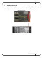
3.3 Inventory Pull-out Tab. . . . . . . . . . . . . . . . . . . . . . . . . . . . . . . . . . . . . . . . . . . . . 36
Chapter 4 Software Management. . . . . . . . . . . . . . . . . . . . . . . . . . . . . . . . . . . . . . . . . . . 37
4.1 InfiniBand Subnet Manager. . . . . . . . . . . . . . . . . . . . . . . . . . . . . . . . . . . . . . . . . 37
4.2 Fabric Inspector (Diagnostics). . . . . . . . . . . . . . . . . . . . . . . . . . . . . . . . . . . . . . . 37
4.3 Upgrading Software (on Managed Systems). . . . . . . . . . . . . . . . . . . . . . . . . . . . 38

Mellanox Technologies
2
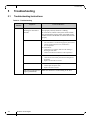
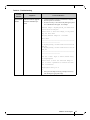
Chapter 5 Troubleshooting . . . . . . . . . . . . . . . . . . . . . . . . . . . . . . . . . . . . . . . . . . . . . . . . 39
5.1 Troubleshooting Instructions. . . . . . . . . . . . . . . . . . . . . . . . . . . . . . . . . . . . . . . . 39
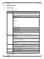
Chapter 6 Specifications . . . . . . . . . . . . . . . . . . . . . . . . . . . . . . . . . . . . . . . . . . . . . . . . . . 41
6.1 SX67X0 Series. . . . . . . . . . . . . . . . . . . . . . . . . . . . . . . . . . . . . . . . . . . . . . . . . . . 41
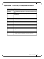
Appendix A Accessory and Replacement Parts . . . . . . . . . . . . . . . . . . . . . . . . . . . . . . . 42
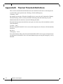
Appendix B Thermal Threshold Definitions . . . . . . . . . . . . . . . . . . . . . . . . . . . . . . . . . 43
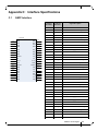
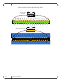
Appendix C Interface Specifications . . . . . . . . . . . . . . . . . . . . . . . . . . . . . . . . . . . . . . . . 44
C.1 QSFP Interface . . . . . . . . . . . . . . . . . . . . . . . . . . . . . . . . . . . . . . . . . . . . . . . . 44
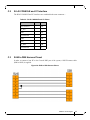
C.2 RJ-45 CONSOLE and I²C Interface. . . . . . . . . . . . . . . . . . . . . . . . . . . . . . . . 46
C.3 RJ45 to DB9 Harness Pinout . . . . . . . . . . . . . . . . . . . . . . . . . . . . . . . . . . . . . 46
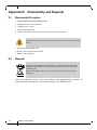
Appendix D Disassembly and Disposal . . . . . . . . . . . . . . . . . . . . . . . . . . . . . . . . . . . . . . 47
D.1 Disassembly Procedure . . . . . . . . . . . . . . . . . . . . . . . . . . . . . . . . . . . . . . . . . 47
D.2 Disposal . . . . . . . . . . . . . . . . . . . . . . . . . . . . . . . . . . . . . . . . . . . . . . . . . . . . . 47
Appendix E Safety Warnings (Multiple Languages) . . . . . . . . . . . . . . . . . . . . . . . . . . . 48
E.1 Nordic Countries Notices . . . . . . . . . . . . . . . . . . . . . . . . . . . . . . . . . . . . . . . . 48
E.2 Installation Safety Warnings (English) . .
. . . . . . . . . . . . . . . . . . . . . . . . . . . 48
E.3 安裝安全性警告 (Chinese) . . . . . . . . . . . . . . . . . . . . . . . . . . . . . . . . . . . . . . 52
E.4 Avertissements de sécurité pour l'installation (French) . . . . . . . . . . . . . . . . . 58
E.5 Installation Sicherheitshinweise(German) . .
. . . . . . . . . . . . . . . . . . . . . . . . . 62
E.6 Advertencias de seguridad de instalación (Spanish) . . . . . . . . . . . . . . . . . . . 65
E.7 Предупреждения по технике безопасности при установке (Rus
sian) . . . 69
E.8 Avertismente privind siguranţa la instalare (Romanian)
. . . . . . . . . . . . . . . . 73
E.9 Sigurnosna upozorenja za instaliranje (Croatian). .
. . . . . . . . . . . . . . . . . . . . 77
E.10 Avvertenze di sicurezza per l’installazione (italiano) . . . . . . . . . . . . . . . . . . 82
E.11 Montaj Güvenlik Uyarıları (Türkçe) . .
. . . . . . . . . . . . . . . . . . . . . . . . . . . . . 86

Mellanox Technologies
1
List of Figures
Figure 1: SX67X0 Front Side View . . . . . . . . . . . . . . . . . . . . . . . . . . . . . . . . . . . . . . . . . . . . . . . . . .4
Figure 2: SX6710/SX6720 Rear Side View . . . . . . . . . . . . . . . . . . . . . . . . . . . . . . . . . . . . . . . . . . . .5
Figure 3: SX6730 Rear Side View . . . . . . . . . . . . . . . . . . . . . . . . . . . . . . . . . . . . . . . . . . . . . . . . . . .5
Figure 4: Air Flow Direction Marking - Power Side I
n
let to Connector Side Outlet . . . . . . . . . . . .8
Figure 5: Air Flow Direction Marking - Connector Side Inlet to Power Side Outlet
. . . . . . . . . . . .9
Figure 6: SX6730 Air Flow Direction - Power Side Inlet to Connector Side Out
let . . . . . . . . . . . . .9
Figure 7: Unlocking the Latches and Extracting the PSU . . . . . . . . . . .
. . . . . . . . . . . . . . . . . . . . .11
Figure 8: BBU Location . . . . . . . . . . . . . . . . . . . . . . . . . . . . . . . . . . . . . . . . . . . . . . . . . . . . . . . . . .11
Figu
re 9: BBU Insertion (Left) and Extraction (Right) . . . . . . . . . .
. . . . . . . . . . . . . . . . . . . . . . . .12
Figure 10: Rack Rail Kit Parts . . . . . . . . . . . . . . . . . . . . . . . . . . . . . . . . . . . . . . . . . . . . . . . . . . . . . .13
Figure 11: Mounting the Outer Rails into the Rack . . . . . . . . . . . . . .
. . . . . . . . . . . . . . . . . . . . . . . .14
Figure 12: Attaching the Inner Rails to the Chassis .
. . . . . . . . . . . . . . . . . . . . . . . . . . . . . . . . . . . . .14
Figure 13: Securing the Chassis in the Inner Rails . . . . . . . . . . . . . . . . . . . . . . . . . . . . . . . . . . . . . .15
Figure 14: Sliding the Switch into the Rack . . . . . .
. . . . . . . . . . . . . . . . . . . . . . . . . . . . . . . . . . . . .15
Figure 15: Pulling the Unit Outwards . . . . . . . . . . . . . . . . . . . . . . . . . . . . . . . . . . . . . . . . . . . . . . . .16
Figure 16: Locking Mechanism . . . . . . . . . . . . . . . . . . . . . . . . . . . . . . . . . . . . . . . . . . . . . . . . . . . . .16
Figure 17: Cable Orientation . . . . . . . . . . . . . . . . . . . . . . . . . . . . . . . . . . . . . . . . . . . . . . . . . . . . . . .1
7
Figu
re 18: Breakout or Fanout Cable . . . . . . . . . . . . . . . . . . . . . . . . . . . . . . . . . . . . . . . . . . . . . . . . .18
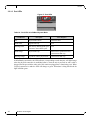
Figure 19: System Status LEDs 5 Minutes After Power On
. . . . . . . . . . . . . . . . . . . . . . . . . . . . . . .19
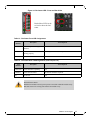
Figure 20: Two Power Inlets - Electric Caution Notifications . . . . . . . . . . . . . . . . . . . . . . . . . . . . .20
Figure 21: PS Unit Pulled Out . . . . . . . . . . . . . . . . . . . . . . . . . . . . . . . . . . . . . . . . . . . . . . . . . . . . . .26
Figure 22: Fan Module Latches . . . . . . . . . . . . . . . . . . . . . . . . . . . . . . . . . . . . . . . . . . . . . . . . . . . . .27
Figure 23: System Status LEDs - Front and Rear sides . . . . . . . . . . . . . . . . . . . . . . . . . . . . . . . . . . .31
Figure 24: Fan Status LED - Front and Rear Sides . . . . . . . . . . . . . . . . . . . . . . . . . . . . . . . . . . . . . .32
Figure 25: Power Status LED . . . . . . . . . . . . . . . . . . . . . . . . . . . . . . . . . . . . . . . . . . . . . . . . . . . . . .33
Figure 26: Rear Side Panel . . . . . . . . . . . . . . . . . . . . . . . . . . . . . . . . . . . . . . . . . . . . . . . . . . . . . . . .3
3
Figu
re 27: Port LEDs . . . . . . . . . . . . . . . . . . . . . . . . . . . . . . . . . . . . . . . . . . . . . . . . . . . . . . . . . . . . .3
5
Figure 28: Pull-out Tab . . . . . . . . . . . . . . . . . . . . . . . . . . . . . . . . . . . . . . . . . . . . . . . . . . . . . . . . . . .3
6
Figure 29: QSFP Connector Male and Female Views . . . . . . . . . . . . . . . . . . . . . . . . . . . . . . . . . . . .45
Figure 30: RJ45 to DB9 Harness Pinout . . . . . . . . . . . . . . . . . . . . . . . . . . . . . . . . . . . . . . . . . . . . . .46

Mellanox Technologies
1
List of Tables
Table 1: Revision History Table . . . . . . . . . . . . . . . . . . . . . . . . . . . . . . . . . . . . . . . . . . . . . . . . . . . .2
Table 2: References . . . . . . . . . . . . . . . . . . . . . . . . . . . . . . . . . . . . . . . . . . . . . . . . . . . . . . . . . . . . .
3
Table 3: Speed and Switching Capabilities . . . . . . . . . . . . . . . . . . . . . . . . . . . . . . . . . . . . . . . . . . .5
Table 4: Management Interfaces and FRUs . . . . . . . . . . . . . . . . . . . . . . . . . . . . . . . . . . . . . . . . . . .5
Table 5: Ordering Part Numbers (OPNs) . . . . . . . . . . . . . . . . . . . . . . . . . . . . . . . . . . . . . . . . . . . . .6
Table 6: Air Flow Label Legend . . . . . . . . . . . . . . . . . . . . . . . . . . . . . . . . . . . . . . . . . . . . . . . . . . . .8
Table 7: Installation Kit Contents . . . . . . . . . . .
. .
. . . . . . . . . . . . . . . . . . . . . . . . . . . . . . . . . . . . .12
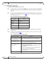
Table 8: Serial Terminal Program Configuration . . . . . . . . . . . . . .
. . . . . . . . . . . . . . . . . . . . . . . .21
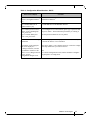
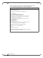
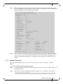
Table 9: Configuration Wizard Session - DHCP . . . . . . . . . . . . . . . . . . . . . . . . . . . . . . . . . . . . . .21
Table 10: Configuration Wizard Session - Static IP Configuration . . . . . . . . . . . . . . . . . . . . . . . . .23
Table 11: LEDs Symbols . . . . . . . . . . . . . . . . . . . . . . . . . . . . . . . . . . . . . . . . . . . . . . . . . . . . . . . . .30
Table 12: System Status LED Assignments . . . . . . . . . . . . . . . . . . . . . . . . . . . . . . . . . . . . . . . . . . .31
Table 13: Fan Status Front LED Assignments . . . . . . . . . . . . . . . . . . . . . . . . . . . . . . . . . . . . . . . . .32
Table 14: Fan Status Rear LED Assignments (One LED per Fan) .
. . .
. . . . . . . . . . . . . . . . . . . . .32
Table 15: Power Supply Unit Status Front LED Assignments . . . . . . . . . . . . . . . . . . . . . . . . . . . . .33
Table 16: Power Supply Unit Status Rear LED Assignments . . . . . . . . . . . . . . . . . . . . . . . . . . . . .34
Table 17: Bad Port LED Assignments . . . . . . . . . . . . . . . . . . . . . . . . . . . . . . . . . . . . . . . . . . . . . . .34
Table 18: Port LEDs in InfiniBand System Mode . . . . . . . . . . . . . . . . . . . . . . . . . . . . . . . . . . . . . .35
Table 19: Troubleshooting . . . . . . . . . . . . . . . . . . . . . . . . . . . . . . . . . . . . . . . . . . . . . . . . . . . . . . . .3
9
Tabl
e 20: SX67X0 Specifications . . . . . . . . . . . . . . . . . . . . . . . . . . . . . . . . . . . . . . . . . . . . . . . . . . .41
Table 21: OPNs for Replacement Parts . . . . . . . . . . . . . . . . . . . . . . . . . . . . . . . . . . . . . . . . . . . . . .42
Table 22: RJ-45 CONSOLE and I²C Pinout . . . . . . . . . . . . . . . . . . . . . . . . . . . . . . . . . . . . . . . . . . .46

Mellanox Technologies
2
Revision History
Table 1 - Revision History Table
Date Revision Description
November 2014 1.0 Initial release

Mellanox Technologies
3
About this Manual
This manual describes the installation and basic use of the Mellanox InfiniBand systems.
Intended Audience
This manual is intended for IT managers and system administrators.
References
Table 2 - References
Document Description
InfiniBand Architecture Specifica-
tion, Volume 1, Release 1.2.1, and
Volume 2, Release
1.3
The InfiniBand Architecture Specification th
at is provided by IBTA
MLNX-OS® User Manual This document contains information regarding configur
ing and managing
MLNX-OS software- see http://www.mellanox.com/page/mlnx_os.
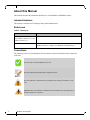
Conventions
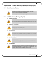
The following icons are used throughout this document to indicate information that is important
to the user.
This icon makes recommendations to the user.
This icon indicates information that is helpful to the user.
This icon indicates a situation that can potentially cause damage to hardware or soft-
ware.
BEWARE! This icon indicates a situation that can potentially cause personal injury or
damage to hardware or software.

Mellanox Technologies
4
1 Introduction to Mellanox SX67X0 Systems
1.1 Overview
The SX67X0 systems provide the highest performing fabric solution in a 1U form factor by
delivering up to 4Tb/s of non-blocking bandwidth with 200ns port-to-port latency.
These systems are the industry's most cost-effective
building blocks for embedded systems and
storage with a need for low port density systems. Whether looking at price-to-performance or
energy-to-performance, these systems offer superior performance, power and space, reducing
capital and operating expenses and providing the best return-on-investment. The systems are an
ideal choice for smaller departmental or back-end clustering uses with high-performance needs,
such as storage, data base and GPGPU clusters.
Powerful servers combined with high-performance storag
e and applications that use increasingly
complex computations are causing data bandwidth requirements to spiral upward. As servers are
deployed with next generation processors, High-Performance Computing (HPC) environments
and Enterprise Data Centers (EDC) need every last bit of bandwidth delivered with Mellanox’s
FDR InfiniBand systems.
Built with Mellanox’s sixth generation SwitchX®-2 In
finiBand FDR 56Gb/s system device,
these standalone systems are an ideal choice for top-of-rack leaf connectivity or for building
small to extremely large sized clusters.
These systems enable efficient computing with features such as static routing, adaptive
routing,
and advanced congestion management. These features ensure the maximum effective fabric
bandwidth by eliminating congestion.
The managed systems comes with an onboard subnet
manage
r, enabling simple, out-of-the-box
fabric bring-up for up to 648 nodes. MLNX-OS® software delivers complete chassis manage-
ment of firmware, power supplies, fans, ports and other interfaces.
Mellanox’s edge systems c
an also be coupled with Mellanox’s Unified Fabric Manager (UFM®)
software for managing scale-out In
finiBand computing environments. UFM enables data center
operators to efficiently provision, monitor and operate the modern data center fabric. UFM
boosts application performance and ensures that the fabric is up and running at all times.
InfiniBand systems come as internally or externally managed. Internally managed sy
stems come
with a CPU that runs the management software (MLNX-OS®) and management ports which are
used to transfer management traffic into the system. Externally managed systems come without
the CPU and management ports and are managed using firmware tools.
Mellanox's InfiniBand to Ethernet gateway, built with Mellanox's SwitchX®-2 based systems,
provides the most
cost-effective, high-performance solution for data center unified connectivity
solutions. Mellanox's gateways enable data centers to operate at up to 56Gb/s network speeds
while seamlessly connecting to 1, 10 and 40GbE networks with low latency (400ns). Existing
LAN infrastructures and management practices can be preserved, easing deployment and provid-
ing significant return-on-investment.
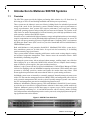
Figure 1: SX67X0 Front Side View

Introduction to Mellanox SX67X0 Systems
Mellanox Technologies
5
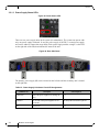
Figure 2: SX6710/SX6720 Rear Side View
Figure 3: SX6730 Rear Side View
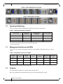
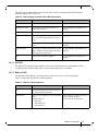
1.2 Speed and Switching
Table 3 describes maximum throughput and interface speed per system model.
Table 3 - Speed and Switching Capabilities
System Model
10GbE* SFP+
Interfaces
40/56GbE QSFP+
Interfaces
Max Throughput
SX6710* N/A 36** 4.032Tb/s
SX6720* N/A 36** 4.032Tb/s
SX6730* N/A 36** 4.032Tb/s
*The system can support 1Gb/s and 10Gb/s
inte
rfaces using QSFP to SFP adapters
**Up to 64x10GbE interfaces
1.3 Management Interfaces and FRUs
Table 4 lists the various management interfaces and available replacement parts per system
model.
Table 4 - Management Interfaces and FRUs
System
Model
USB
MGT (2
Ports)
I²C* Console*
Replaceable
PSU
Replaceable
Fan
SX6710 Rear Rear Rear Rear Yes Yes
SX6720 Rear Rear Rear Rear Yes Yes
SX6730 Rear Rear Rear Rear Yes Yes
*The same connector is used for t
he
I²C and the console interfaces.
1.4 Features
For a full feature list, please refer to the system’s product brief:
http://www.mellanox.com/related-docs/pro
d_ib_switch_systems/PB_SX6710.pdf

Mellanox Technologies
6
1.5 Certifications
The list of certifications (such as EMC, Safety and others) per system for different regions of the
world is located on the Mellanox website at:
http://www.mellanox.com/pa
ge/environmental_compliance
1.6 Ordering Information
the following table lists ordering information for the available systems. Please pay attention to
the airflow direction when ordering your system. For more details, see “Air Flow” on page 8.
Table 5 - Ordering Part Numbers (OPNs)
System
Model
OPN Description
SX6710 MSX6710-FB2F2 SwitchX®-2 based FDR InfiniBand 1U Switch, 36 QSFP+ ports, 2 Power Supplies
(AC), x86 dual core, short depth, rear to front airflow, Rail Kit, RoHS6
MSX6710-FS2F2 SwitchX®-2 based FDR InfiniBand 1U Switch, 36 QSFP+ ports, 2 Power Supplies
(AC),
x86 dual core, standard depth, rear to front airflow, Rail Kit, RoHS6
SX6720 MSX6720-FS2F2 SwitchX®-2 based FDR InfiniBand 1U Switch BBU ready,36 QSFP+ ports, 2 Power
Su
pplies (
AC), x86 dual core, standard depth, rear to front airflow, Rail Kit, RoHS6
SX6730 MSX6730-FS2F2 SwitchX®-2 based FDR InfiniBand Switch NEBS certified, 36 QSFP ports, non-
blo
ck
ing switching capacity of 4Tbps, 2 Power Supplies (DC), Standard depth, Man-
aged, rear to front airflow, Rail Kit must be pur
chased separately, RoHS6

Installation
Mellanox Technologies
7
2Installation
Installation and initialization of the system require attention to the normal mechanical, power,
and thermal precautions for rack-mounted equipment.
The rack mounting holes conform to the EIA-310 standard for 19-inch racks. Take
precautions to guarantee proper ventilation in order to maintain good airflow at ambi-
ent temperature.
The installation procedure for the system involv
es the following phases:
1. Follow the safety warnings in Section 2.1.
2. Pay attention to the air flow consideration within the
system an
d rack - refer to “Air Flow” on
page 8.
3. Make sure that none of the package contents is missing or damaged - see “Package Contents”
on page 9
4. Power on the system - refer to “Initial Power On” on page 19
5. Perform system bring-up - see “Bring-Up of Managed Systems” on page 20
FRU replacements are described in Section 2.8 on page 25.
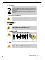
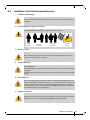
2.1 Safety Warnings
Prior to the installation, please review the safety warnings as follows:
For Nordic Countries Notices see Section E.1, “Nordic Countries Notices,” on page 48.
For Safety Warnings in English see Section E.1, “Nordic Countries Notices,” on page 48.
For Safety Warnings in Chinese see Section E.3 on page 52.
For Safety Warnings in French see Section E.4, “Avertissements de sécurit
é pour l'installation
(Frenc
h),” on page 58.
For Safety Warnings in German Section E.5, “Installation Sicherheitshinweise(German),” on
page 62.
For Safety Warnings in Spanish see Section E.6, “Advertencias de seguridad de instalación
(Spanish),” on page 65.
For Safety Warnings in Russian see Section E.7, “Пре
дупреждения по техник
е безопасности
при установке (Russian),” on page 69.
For Safety Wa
rnings in Romanian see Section E.8, “Avertismente privind siguranţa la instalare
(Ro
manian),” on page 73.
For Safety Warnings in Croatian see Section E.9, “Sigurnosna upozorenja za ins
taliranje (Croa-
tian),” on page 77.
For Safety Warnings in Italian see Section E.10, “Avvertenze di sicurezza per l’installaz
ione
(italiano),” on page 82.
For Safety Warnings in Turkish see Section E.11, “Montaj Güvenlik Uyarıları (Türkçe),” on
page 86.

Mellanox Technologies
8
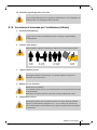
2.2 Air Flow
Mellanox systems are offered with two air flow patterns:
• Connector (front) side inlet to power side outlet - marked with red labels on the power
supply side.
• P
ower (rear) side inlet to connector side outlet - marked with blue labels on th
e power
supply side as shown in Figure 4.
All servers and systems in the same rack should be planned with the same airflow
direction.
All FRU components need to have the same air flow direction. A mismatch in the air
flow will affect the heat
dissipation.
Table 6 provides an air flow color legend and respective OPN designations.
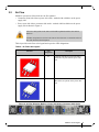
Table 6 - Air Flow Label Legend
Direction
OPN
Designation
Description
R Connector side inlet to power side outlet.
Red latches are placed on the power inlet
side.
F Power side inlet to connector side outlet.
Blue latches are placed on the power inlet
side.
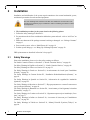
Figure 4: Air Flow Direction Marking - Power Side Inlet to Connector Side Outlet

Installation
Mellanox Technologies
9
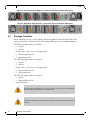
Figure 5: Air Flow Direction Marking - Connector Side Inlet to Power Side Outlet
Figure 6: SX6730 Air Flow Direction - Power Side Inlet to Connector Side Outlet
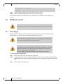
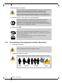
2.3 Package Contents
Before installing your new system, unpack it and check against the parts list below that all the
parts have been sent. Check the parts for visible damage that may have occurred during shipping.
The SX6710 package content is as follows:
• 1 – System
• 1 – Rail kit
• Power cables – Type C13 to C14, length 183cm
• 1 – Harness DB9 to RJ-45
• 1 – Quick Start Guide
The SX6720 package content is as follows:
• 1 – System
• 1 – Rail kit
• Power cables – Type C13 to C14, length 183cm
• 1 – Harness DB9 to RJ-45
• 1 – Quick Start Guide
The SX6730 package content is as follows:
• 1 – System
• 1 – Harness DB9 to RJ-45
• Quick Start Guide
For connection of the SX6730, a DC cable is required. Such a cable is not included in
the basic package and should be ordered separately.
If anything is damaged or missing, contact your sales representative at support@mella-
nox.com.

Mellanox Technologies
10
2.4 Mounting Options
2.4.1 Battery Backup Unit (BBU) Installation for SX6720
If the BBU is deformed, leaking, corroded or visually damaged, replace it immediately
Do not use a BBU that was not provided by Mellanox Technologies
• A BBU that has not been used for two years or longer past ts printed manufacturing
date is unusable.
• A BBU that is older than five years, according to the printed manufacturing date,
has reached its "end of life"
state and may not provide enough energy to handle the
platform.
• In case the battery should be replaced, software notifications will appear on a
mon
thl
y basis, starting three months before EOL time.
A new Battery Back-up Unit (BBU) will be approximately 50% charged when you receive it. In
case of a power outage, only a fully charged BBU can supply power of up to 5 minutes to the sys-
tem.
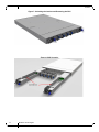
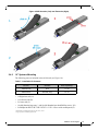
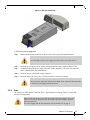
2.4.1.1 Installing the Battery
Step 1. Extract the power FRU module from the chassis of the switch by unlocking all latches
Step 2. Insert the BBU into the empty slot in the module by sliding it in and pushing the top end of it
down until it snaps into place, as illustrated in the left image of Figure 9.
Step 3. Slide the module back into the chassis.
2.4.1.2 Extracting the Battery
Step 1. Extract the power FRU module from the chassis of the switch by unlocking all latches.
Step 2. Press both release buttons simultaneously and lift the battery up to remove it, as illustrated in
the right image of Figure 9.
Step 3. Slide the module back into the chassis.

Installation
Mellanox Technologies
11
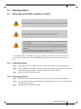
Figure 7: Unlocking the Latches and Extracting the PSU
Figure 8: BBU Location

Mellanox Technologies
12
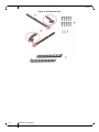
Figure 9: BBU Insertion (Left) and Extraction (Right)
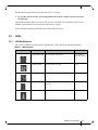
2.4.2 19” Systems Mounting
Table 7 - Installation Kit Contents
Kit OPN Rack Size Rack Depth Range
MTEF-KIT-B Short 17"-24"
MTEF-KIT-S Standard (long) 24"-38"
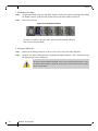
The following parts are included in the rail kit rack (see Figure 10):
• 1x Right inner rail (A)
• 1x Left inner rail (B)
• 2x Outer rails (C)
• 10x M6 Standard cage nuts¹ ² and 10x M6 S
tandard pan-head Phillips screws¹ (D)
•
2x Phillips100 DEG F.H TYPE-I ST.ST 6-32 X 1/4 screw with around patch (E).
¹ Other threads are available by special order: M5, 10-32, 12-24
² G-type cage-nut is available by special order.

Installation
Mellanox Technologies
13
Figure 10: Rack Rail Kit Parts

Mellanox Technologies
14
Planning the system’s placement in the rack
Before mounting the system to the rack, select the way you wi
sh to place the system. Pay atten-
tion to the airflow within the rack cool
ing, connector and cabling options.
While planning how to place the system, review the following points:
• Make sure the system air flow is compatible with your installation selection. It is impor-
tant to keep the airflow within the rack
in the same direction.
• In case there are cables that cannot bend w
ithin the rack or in case more space is needed
for cable bending radius, it is possible to recess the connector side or the FRU side by
3” or 4” (7.62 or 10.16cm) by optional placement of the system’s rails.
• The FRU side is extractable. Mounting the sliding rail
inverted to
the system will allow
you to slide the FRU side of the system, in and out.
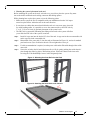
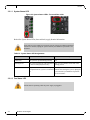
Step 1. Install 10 cage nuts into the desired 1U slot of the rack: 4 cage nuts in the non-extractable side
and 6 cage nuts in the extractable side.
Step 2. Mount both of the outer rails (C) into the rack (as illustrated in Figure 11), and use 8 standard
pan-head screws (D) to fix them to the rack. Do not tighten the scre
ws yet.
Step 3. If cable accommodation is required, rout the power cable and/or Eth cable through either of the
outer rails.
Step 4. Secure the switch to the left and right inner rails (A+B), by gently pushing the switch chassis’
pins through the slider key holes, until locking occurs. Secure the chassis in the inner rails
screwing the 2 flat head Phillips screws in the designated points.
Figure 11: Mounting the Outer Rails into the Rack
Figure 12: Attaching the Inner Rails to the Chassis

Installation
Mellanox Technologies
15
Figure 13: Securing the Chassis in the Inner Rails
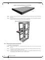
Step 5. Slide the switch into the rack by carefully pushing the inner rails into the outer rails installed on
the rack.
Step 6. When fully inserted, fix the switch by closing the remaining 2 screws in the middle and tighten-
ing the 8 screws inserted in Step 2 with a torque of Min 2Nm.
Figure 14: Sliding the Switch into the Rack
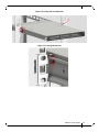
2.4.2.1 Removing the System from the Rack
To remove a unit from the rack:
Step 1. Unscrew the two M6 screws securing the front of the inner rails’ ears to the outer rails and to
the rack.
Step 2. Pull the unit out until braking is felt. For safety purposes, the locking mechanism will not allow
a complete removal of the unit at this stage.
Step 3. Press on the locking spring (appears in red in Figure 16) on both sides simultaneously, and con-
tinue pulling the unit towards you until it is fully removed.
Pagina se încarcă ...
Pagina se încarcă ...
Pagina se încarcă ...
Pagina se încarcă ...
Pagina se încarcă ...
Pagina se încarcă ...
Pagina se încarcă ...
Pagina se încarcă ...
Pagina se încarcă ...
Pagina se încarcă ...
Pagina se încarcă ...
Pagina se încarcă ...
Pagina se încarcă ...
Pagina se încarcă ...
Pagina se încarcă ...
Pagina se încarcă ...
Pagina se încarcă ...
Pagina se încarcă ...
Pagina se încarcă ...
Pagina se încarcă ...
Pagina se încarcă ...
Pagina se încarcă ...
Pagina se încarcă ...
Pagina se încarcă ...
Pagina se încarcă ...
Pagina se încarcă ...
Pagina se încarcă ...
Pagina se încarcă ...
Pagina se încarcă ...
Pagina se încarcă ...
Pagina se încarcă ...
Pagina se încarcă ...
Pagina se încarcă ...
Pagina se încarcă ...
Pagina se încarcă ...
Pagina se încarcă ...
Pagina se încarcă ...
Pagina se încarcă ...
Pagina se încarcă ...
Pagina se încarcă ...
Pagina se încarcă ...
Pagina se încarcă ...
Pagina se încarcă ...
Pagina se încarcă ...
Pagina se încarcă ...
Pagina se încarcă ...
Pagina se încarcă ...
Pagina se încarcă ...
Pagina se încarcă ...
Pagina se încarcă ...
Pagina se încarcă ...
Pagina se încarcă ...
Pagina se încarcă ...
Pagina se încarcă ...
Pagina se încarcă ...
Pagina se încarcă ...
Pagina se încarcă ...
Pagina se încarcă ...
Pagina se încarcă ...
Pagina se încarcă ...
Pagina se încarcă ...
Pagina se încarcă ...
Pagina se încarcă ...
Pagina se încarcă ...
Pagina se încarcă ...
Pagina se încarcă ...
Pagina se încarcă ...
Pagina se încarcă ...
Pagina se încarcă ...
Pagina se încarcă ...
Pagina se încarcă ...
Pagina se încarcă ...
Pagina se încarcă ...
Pagina se încarcă ...
Pagina se încarcă ...
-
 1
1
-
 2
2
-
 3
3
-
 4
4
-
 5
5
-
 6
6
-
 7
7
-
 8
8
-
 9
9
-
 10
10
-
 11
11
-
 12
12
-
 13
13
-
 14
14
-
 15
15
-
 16
16
-
 17
17
-
 18
18
-
 19
19
-
 20
20
-
 21
21
-
 22
22
-
 23
23
-
 24
24
-
 25
25
-
 26
26
-
 27
27
-
 28
28
-
 29
29
-
 30
30
-
 31
31
-
 32
32
-
 33
33
-
 34
34
-
 35
35
-
 36
36
-
 37
37
-
 38
38
-
 39
39
-
 40
40
-
 41
41
-
 42
42
-
 43
43
-
 44
44
-
 45
45
-
 46
46
-
 47
47
-
 48
48
-
 49
49
-
 50
50
-
 51
51
-
 52
52
-
 53
53
-
 54
54
-
 55
55
-
 56
56
-
 57
57
-
 58
58
-
 59
59
-
 60
60
-
 61
61
-
 62
62
-
 63
63
-
 64
64
-
 65
65
-
 66
66
-
 67
67
-
 68
68
-
 69
69
-
 70
70
-
 71
71
-
 72
72
-
 73
73
-
 74
74
-
 75
75
-
 76
76
-
 77
77
-
 78
78
-
 79
79
-
 80
80
-
 81
81
-
 82
82
-
 83
83
-
 84
84
-
 85
85
-
 86
86
-
 87
87
-
 88
88
-
 89
89
-
 90
90
-
 91
91
-
 92
92
-
 93
93
-
 94
94
-
 95
95


Mellanox Technologies SX6730 Hardware User Manual
- Tip
- Hardware User Manual
în alte limbi
- English: Mellanox Technologies SX6730
- italiano: Mellanox Technologies SX6730
Lucrări conexe
-
Mellanox Technologies SX6710 Hardware User Manual
-
-
Mellanox Technologies MSX6036G-2SRS Manual de utilizare
-
-
-
-
-
-
-