
Outdoor WiFi System
Models:
UAP-Outdoor/UAP-Outdoor 5G


1
Introduction
Introduction
Thank you for purchasing a UniFi AP-Outdoor series product.
This Quick Start Guide is for use with the following models:
Model Operating Frequency*
UAP-Outdoor 2.4 GHz
UAP-Outdoor 5G 5 GHz
* For detailed specifications, refer to the User Guide on the CD.
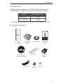
Package Contents
Outdoor WiFi System
Models:
UAP-Outdoor/UAP-Outdoor 5G
UniFi
AP-Outdoor
Wall Mount
Bracket
Metal Strap Quick Start
Guide
UniFi Controller
CD with User Guide
Antennas
24V PoE
Adapter
Power Cord Screws
(Qty. 3)
Anchors

2
UniFi
™
AP-Outdoor
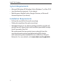
System Requirements
• Microsoft Windows XP, Windows Vista, Windows 7, or Mac OS X
• Java Runtime Environment 1.6 (or above)
• Web Browser: Mozilla Firefox, Google Chrome, or Microsoft
Internet Explorer 8 (or above)
Installation Requirements
• Drill and 6 mm drill bit (for wall-mounting)
• Flathead screwdriver (for pole-mounting)
• Shielded Category 5 (or above) cabling should be used for all
wired Ethernet connections and should be grounded through
the AC ground of the PoE.
We recommend that you protect your networks from the
most brutal environments and devastating ESD attacks
with industrial-grade shielded Ethernet cable from Ubiquiti
Networks. For more details, visit www.ubnt.com/toughcable

3
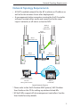
Network Topology Requirements
Network Topology Requirements
• A DHCP-enabled network (for the AP to obtain an IP address as
well as for the wireless clients after deployment)
• A management station computer running the UniFi Controller
software, located either onsite and connected to the same
Layer-2 network, or off-site in a cloud or NOC
or
Router
O-Site
Cloud/NOC
2
On-Site
Management Station
Wired
UAP-Outdoor
Wireless
Uplinked
1
UAP-Outdoor
Wired
UAP-Outdoor 5G
Wired
UAP-Outdoor 5G
Wired
UAP-Outdoor
Sample Network Diagram
¹ Please refer to the UniFi Outdoor WiFi System | UAP-Outdoor
User Guide on the CD for setting up wireless-linked APs.
² All UniFi APs support off-site management controllers. See the
User Guide for setup details.

4
UniFi
™
AP-Outdoor
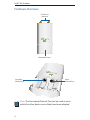
Hardware Overview
Connects to
Antennas
Removable Cover
Secondary
Ethernet Port
Main
Ethernet Port
Note: The Secondary Ethernet Port can be used as as an
uplink for other devices once they have been adopted.

5
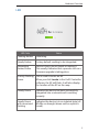
Hardware Overview
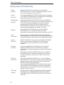
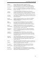
LED
LED Color Status
Flashing Amber Initializing.
Steady Amber Factory default, waiting to be integrated.
Alternating
Amber/Green
Device is busy; do not touch or unplug it.
This usually indicates that a process such as a
firmware upgrade is taking place.
Quickly Flashing
Green
This is used to locate an AP.
When you click Locate in the UniFi Controller
software, the AP will flash. It will also display
the location of the AP on the map.
Steady Green Indicates the device has been successfully
integrated into a network and is working
properly.
Steady Green
with occasional
flashing
Indicates the device is in an isolated state (all
WLANs are brought down until an uplink is
found).

6
UniFi
™
AP-Outdoor
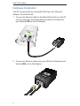
Hardware Installation
The AP is powered by the included PoE (Power over Ethernet)
Adapter. To install the AP:
1. Connect an Ethernet cable to the Main Ethernet Port on the AP.
Connect the other end of the Ethernet cable to the Ethernet
port labeled POE on the PoE Adapter.
2. Connect an Ethernet cable from your LAN to the Ethernet port
labeled LAN on the PoE Adapter.

7
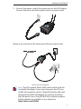
Hardware Installation
3. Connect the power cord to the power port on the PoE Adapter.
Connect the other end of the power cord to a power outlet.
Below is an overview of the Power over Ethernet connections.
Power Connection Diagram
Note: The AP supports Passive PoE, which works with the
included PoE adapter. If you want to power the AP from
an 802.3af compliant switch, Ubiquiti Networks offers the
optional Instant 802.3af Adapter to instantly transform
any PoE device into a fully 48V 802.3af compliant product.
Product details are available on our website at
http://ubnt.com/8023af

8
UniFi
™
AP-Outdoor
Mounting the UniFi AP-Outdoor
The AP can be mounted on a wall or pole.
Wall Mount
To mount the AP on a wall, use the included Wall Mount Bracket,
screws, and anchors.
1. Align the Wall Mount Bracket to the desired position on a wall.
2. Use a pencil to mark the holes on the wall.
3. Use a drill and 6 mm drill bit to drill the holes in the wall.
4. Insert the 3 screw anchors into the wall.
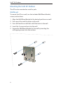
5. Secure the Wall Mount Bracket to the wall by inserting the
self-tapping screws into the anchors.

9
Hardware Installation
6. Align the notches on the AP with the notches on the Wall
Mount Bracket, and slide the AP down until it locks into place.
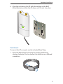
Pole Mount
To mount the AP on a pole, use the included Metal Strap:
1. Open the Metal Strap by turning the locking mechanism
counter-clockwise. You can loosen it by hand or use a flathead
screwdriver.

10
UniFi
™
AP-Outdoor
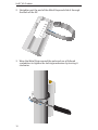
2. Straighten out the end of the Metal Strap and slide it through
the back of the AP.
3. Wrap the Metal Strap around the pole and use a flathead
screwdriver to tighten the locking mechanism by turning it
clockwise.

11
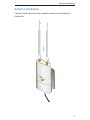
Antenna Installation
Antenna Installation
Connect each antenna to an antenna connector by rotating it
clockwise.

12
UniFi
™
AP-Outdoor
Software Installation
Insert the UniFi Controller software CD into your CD-ROM drive
and follow the instructions for your specific computer type.
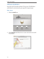
Mac Users
1. Click the Install icon.
2. Click Continue and follow the on-screen instructions to install
the software.

13
Software Installation
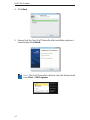
3. Go to Go > Applications and double-click the UniFi icon.
Proceed to Configuring the UniFi Controller Software on page 15.
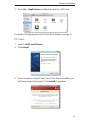
PC Users
1. Launch UniFi-installer.exe.
2. Click Install.
3. If your computer doesn't have Java 1.6 or above installed, you
will be prompted to install it. Click Install to continue.

14
UniFi
™
AP-Outdoor
4. Click Next.
5. Ensure that the Start UniFi Controller after installation option is
checked and click Finish.
Note: The UniFi Controller software can also be launched
from Start > All Programs.

15
Software Installation
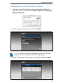
Configuring the UniFi Controller Software
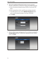
1. The UniFi Controller software startup will begin. When the
option becomes available, click Launch a Browser to Manage
Wireless Network.
2. Select your language and country. Click Next.
Note: U.S. product versions are locked to the U.S. Country
Code to ensure compliance with FCC regulations.
3. Select the devices that you want to configure and click Next.

16
UniFi
™
AP-Outdoor
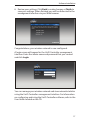
4. The UniFi Installation Wizard will create a secure, primary
wireless network for your devices. Perform the following steps:
a. Enter the wireless network name (SSID) in the Secure SSID
field.
b. Enter a passphrase to be used for your primary network.
c. To enable guest access, select Enable Guest Access and
enter a guest network name in the Guest SSID field.
d. Click Next.
5. Enter an admin name and password to use when accessing the
management interface. Confirm your password in the Confirm
field. Click Next.

17
Software Installation
6. Review your settings. Click Back to make changes or Finish to
save your settings. When finished, you will be redirected to the
management interface via your Web browser.
Congratulations, your wireless network is now configured.
A login screen will appear for the UniFi Controller management
interface. Enter the admin name and password that you created
and click Login.
You can manage your wireless network and view network statistics
using the UniFi Controller management interface. For information
on configuring and using the UniFi Controller software, refer to the
User Guide located on the CD.

18
UniFi
™
AP-Outdoor
Installer Compliance Responsibility
Devices must be professionally installed and it is the professional
installer's responsibility to make sure the device is operated within
local country regulatory requirements.
Safety Notices
1. Read, follow, and keep these instructions.
2. Heed all warnings.
3. Only use attachments/accessories specified by the manufacturer.
WARNING: Do not use this product in location that can be
submerged by water.
WARNING: Avoid using this product during an electrical
storm. There may be a remote risk of electric shock from
lightning.
Electrical Safety Information
1. Compliance is required with respect to voltage, frequency, and current
requirements indicated on the manufacturer’s label. Connection to a
different power source than those specified may result in improper
operation, damage to the equipment or pose a fire hazard if the
limitations are not followed.
2. There are no operator serviceable parts inside this equipment. Service
should be provided only by a qualified service technician.
3. This equipment is provided with a detachable power cord which has
an integral safety ground wire intended for connection to a grounded
safety outlet.
a. Do not substitute the power cord with one that is not the provided
approved type. Never use an adapter plug to connect to a 2-wire
outlet as this will defeat the continuity of the grounding wire.
b. The equipment requires the use of the ground wire as a part of the
safety certification, modification or misuse can provide a shock
hazard that can result in serious injury or death.
c. Contact a qualified electrician or the manufacturer if there are
questions about the installation prior to connecting the equipment.
d. Protective earthing is provided by Listed AC adapter. Building
installation shall provide appropriate short-circuit backup
protection.
e. Protective bonding must be installed in accordance with local
national wiring rules and regulations.
Pagina se încarcă...
Pagina se încarcă...
Pagina se încarcă...
Pagina se încarcă...
Pagina se încarcă...
Pagina se încarcă...
Pagina se încarcă...
Pagina se încarcă...
-
 1
1
-
 2
2
-
 3
3
-
 4
4
-
 5
5
-
 6
6
-
 7
7
-
 8
8
-
 9
9
-
 10
10
-
 11
11
-
 12
12
-
 13
13
-
 14
14
-
 15
15
-
 16
16
-
 17
17
-
 18
18
-
 19
19
-
 20
20
-
 21
21
-
 22
22
-
 23
23
-
 24
24
-
 25
25
-
 26
26
-
 27
27
-
 28
28


Ubiquiti UAP-Outdoor Ghid de inițiere rapidă
- Tip
- Ghid de inițiere rapidă
- Acest manual este potrivit și pentru
în alte limbi
- English: Ubiquiti UAP-Outdoor Quick start guide
- italiano: Ubiquiti UAP-Outdoor Guida Rapida
Lucrări înrudite
-
Ubiquiti Networks UAP-AC Manualul utilizatorului
-
Ubiquiti UniFI UAP-AC Ghid de inițiere rapidă
-
-
Ubiquiti Networks UniFi Manualul utilizatorului
-
-
-
-
-
-
Ubiquiti airRouter HP Ghid de inițiere rapidă