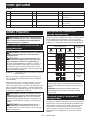
Makita UC010G Cordless Chain Saw Manual de utilizare
- Categorie
- Ferăstraie cu lanț electric
- Tip
- Manual de utilizare

UC010G
UC011G
UC012G
UC013G
EN Cordless Chain Saw INSTRUCTION MANUAL 9
SL Brezžična verižna žaga NAVODILA ZA UPORABO 22
SQ Sharrë me zinxhir me bateri MANUALI I PËRDORIMIT 35
BG Акумулаторен верижен
трион РЪКОВОДСТВО ЗА
ЕКСПЛОАТАЦИЯ 49
HR Bežična lančana pila PRIRUČNIK S UPUTAMA 64
МК Безжична моторна пила УПАТСТВО ЗА УПОТРЕБА 77
SR Бежична ланчана тестера УПУТСТВО ЗА УПОТРЕБУ 92
RO Ferăstrău cu lanţ cu
acumulator MANUAL DE INSTRUCŢIUNI 107
UK Бездротова ланцюгова
пила ІНСТРУКЦІЯ З
ЕКСПЛУАТАЦІЇ 122
RU Цепная пила с питанием от
аккумуляторной батареи РУКОВОДСТВО ПО
ЭКСПЛУАТАЦИИ 137

2
Fig.1
12
345
6
11
13
15 12
9
14
16
7
8
10
Fig.2

3
1
1
2
3
Fig.3
12
Fig.4
1
2
Fig.5
1
2
Fig.6
23
1
23
1
Fig.7
1
Fig.8

4
32
1
Fig.9
1
Fig.10
12
Fig.11
1
32
Fig.12
1
Fig.13
32
1
Fig.14

5
1
Fig.15
32
1
Fig.16
1
Fig.17
1
2
Fig.18
1
23
Fig.19
1
2
Fig.20
Fig.21

6
Fig.22
Fig.23
Fig.24
Fig.25
A
B
A
B
Fig.26
Fig.27
2 1/2
45o
1
45o
Fig.28
1
2
2
33
Fig.29

7
Fig.30
Fig.31
2
1
Fig.32
22
11
31
Fig.33
30
30
55 55
Fig.34
1
2
Fig.35
30 1/5
1
Fig.36
Fig.37

8
Fig.38
Fig.39
12
Fig.40
1
2
Fig.41
12
Fig.42

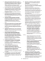
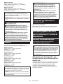
9ENGLISH
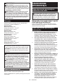
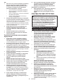
ENGLISH (Original instructions)
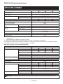
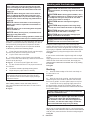
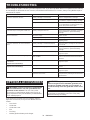
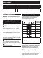
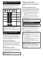
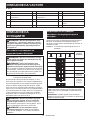
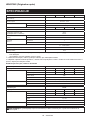
SPECIFICATIONS
Model: UC010G UC011G UC012G UC013G
Overall length
(without guide bar) 445 mm
Rated voltage D.C. 36 V - 40 V max
Net weight *1 4.5 kg
*2 6.1 - 6.8 kg
Standard guide bar length 300 mm 350 mm 400 mm 450 mm
Recommended guide bar length 300 - 450 mm
Applicable saw chain type
(refer to the table below) 91PX
80TXL
Sprocket
(91PX) Number of teeth 6
Pitch 3/8″
Sprocket
(80TXL) Number of teeth 7
Pitch 0.325″
Chain speed 0 - 25.5 m/s
(0 - 1,530 m/min)
Chain oil tank volume 260 cm3
Protection degree IPX4
• Duetoourcontinuingprogramofresearchanddevelopment,thespecicationshereinaresubjecttochange
without notice.
• Specicationsmaydierfromcountrytocountry.
*1: Weight, without the saw chain, guide bar, guide bar cover, oil and battery cartridge(s).
*2:Thelightestandheaviestcombinationofweight,accordingtoEPTA-Procedure01/2014.Theweightmaydier
depending on the attachment(s), including the battery cartridge(s).
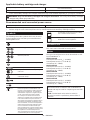
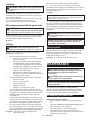
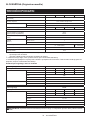
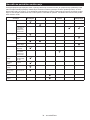
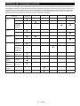
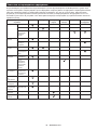
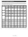
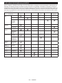
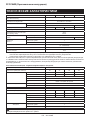
Saw chain, guide bar, and sprocket combination
Saw chain type 91PX
Number of drive links 46 52 56 62
Guide bar Guide bar length 300 mm 350 mm 400 mm 450 mm
Cutting length 268 mm 324 mm 361 mm 418 mm
Pitch 3/8″
Gauge 1.3 mm
Type Sprocket nose bar
Sprocket Number of teeth 6
Pitch 3/8″
Saw chain type 80TXL
Number of drive links 51 59 64 70
Guide bar Guide bar length 300 mm 350 mm 400 mm 450 mm
Cutting length 259 mm 325 mm 366 mm 416 mm
Pitch 0.325″
Gauge 1.1 mm
Type Sprocket nose bar
Sprocket Number of teeth 7
Pitch 0.325″
WARNING:Useappropriatecombinationoftheguidebarandsawchain.Otherwisepersonalinjurymay
result.

10 ENGLISH
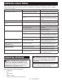
Applicable battery cartridge and charger
Battery cartridge BL4040 / BL4050F*
* : Recommended battery
Charger DC40RA / DC40RB / DC40RC
•
Some of the battery cartridges and chargers listed above may not be available depending on your region of residence.
WARNING: Only use the battery cartridges and chargers listed above. Use of any other battery cartridges
andchargersmaycauseinjuryand/orre.
Recommended cord connected power source
Portable power pack PDC01
• The cord connected power source(s) listed above may not be available depending on your region of residence.
• Before using the cord connected power source, read instruction and cautionary markings on them.
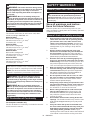
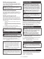
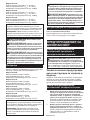
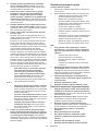
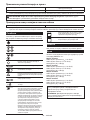
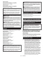
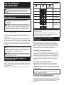
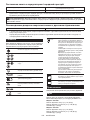
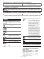
Symbols
The followings show the symbols which may be used
for the equipment. Be sure that you understand their
meaning before use.
Read instruction manual.
Wear safety glasses.
Wear ear protection.
Wear a helmet, goggles and ear protection.
Maximum permissible cut length
Always use two hands when operating the
chain saw.
Beware of chain saw kickback and avoid
contact with bar tip.
Direction of chain travel
Sawchainoiladjustment
Ni-MH
Li-ion Only for EU countries
Due to the presence of hazardous com-
ponents in the equipment, waste electrical
and electronic equipment, accumulators
and batteries may have a negative impact
on the environment and human health.
Do not dispose of electrical and electronic
appliances or batteries with household waste!
In accordance with the European Directive on
waste electrical and electronic equipment and on
accumulators and batteries and waste accumu-
lators and batteries, as well as their adaptation to
national law, waste electrical equipment, batter-
ies and accumulators should be stored sepa-
rately and delivered to a separate collection point
for municipal waste, operating in accordance with
the regulations on environmental protection.
This is indicated by the symbol of the crossed-
out wheeled bin placed on the equipment.
Guaranteed sound power level according
to EU Outdoor Noise Directive.
Sound power level according to Australia
NSW Noise Control Regulation.
Intended use
This chain saw is intended for sawing wood.
Noise
The typical A-weighted noise level determined accord-
ing to EN62841-4-1:
Model UC010G
Sound pressure level (LpA) : 91 dB(A)
Sound power level (LWA) : 102 dB (A)
Uncertainty (K) : 3 dB(A)
Model UC011G
Sound pressure level (LpA) : 91 dB(A)
Sound power level (LWA) : 102 dB (A)
Uncertainty (K) : 3 dB(A)
Model UC012G
Sound pressure level (LpA) : 91 dB(A)
Sound power level (LWA) : 102 dB (A)
Uncertainty (K) : 3 dB(A)
Model UC013G
Sound pressure level (LpA) : 91 dB(A)
Sound power level (LWA) : 102 dB (A)
Uncertainty (K) : 3 dB(A)
NOTE: The declared noise emission value(s) has
been measured in accordance with a standard test
method and may be used for comparing one tool with
another.
NOTE: The declared noise emission value(s)
may also be used in a preliminary assessment of
exposure.

11 ENGLISH
WARNING: Wear ear protection.
WARNING: The noise emission during actual
use of the power tool can dier from the declared
value(s) depending on the ways in which the
tool is used especially what kind of workpiece is
processed.
WARNING: Be sure to identify safety mea-
sures to protect the operator that are based on an
estimation of exposure in the actual conditions of
use (taking account of all parts of the operating
cycle such as the times when the tool is switched
o and when it is running idle in addition to the
trigger time).
Vibration
The vibration total value (tri-axial vector sum) deter-
mined according to EN62841-4-1:
Model UC010G
Work mode: cutting wood
Vibration emission (ah,W) : 4.4 m/s2
Uncertainty (K) : 1.5 m/s2
Model UC011G
Work mode: cutting wood
Vibration emission (ah,W) : 4.4 m/s2
Uncertainty (K) : 1.5 m/s2
Model UC012G
Work mode: cutting wood
Vibration emission (ah,W) : 4.4 m/s2
Uncertainty (K) : 1.5 m/s2
Model UC013G
Work mode: cutting wood
Vibration emission (ah,W) : 4.4 m/s2
Uncertainty (K) : 1.5 m/s2
NOTE: The declared vibration total value(s) has been
measured in accordance with a standard test method
and may be used for comparing one tool with another.
NOTE: The declared vibration total value(s) may also
be used in a preliminary assessment of exposure.
WARNING: The vibration emission during
actual use of the power tool can dier from the
declared value(s) depending on the ways in which
the tool is used especially what kind of workpiece
is processed.
WARNING: Be sure to identify safety mea-
sures to protect the operator that are based on an
estimation of exposure in the actual conditions of
use (taking account of all parts of the operating
cycle such as the times when the tool is switched
o and when it is running idle in addition to the
trigger time).
EC Declaration of Conformity
For European countries only
The EC declaration of conformity is included as Annex A
to this instruction manual.
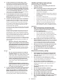
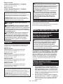
SAFETY WARNINGS
General power tool safety warnings
WARNING: Read all safety warnings, instruc-
tions, illustrations and specications provided
with this power tool. Failure to follow all instructions
listedbelowmayresultinelectricshock,reand/or
seriousinjury.
Save all warnings and instruc-
tions for future reference.
The term "power tool" in the warnings refers to your
mains-operated (corded) power tool or battery-operated
(cordless) power tool.
General chain saw safety warnings
1. Keep all parts of the body away from the saw
chain when the chain saw is operating. Before
you start the chain saw, make sure the saw
chain is not contacting anything. A moment of
inattention while operating chain saws may cause
entanglement of your clothing or body with the
saw chain.
2. Always hold the chain saw with your right
hand on the rear handle and your left hand on
the front handle. Holding the chain saw with a
reversedhandcongurationincreasestheriskof
personalinjuryandshouldneverbedone.
3.
Hold the chain saw by insulated gripping sur-
faces only, because the saw chain may contact
hidden wiring. Saw chains contacting a "live" wire
may make exposed metal parts of the chain saw
"live" and could give the operator an electric shock.
4. Wear eye protection. Further protective equip-
ment for hearing, head, hands, legs and feet is
recommended. Adequate protective equipment
willreducepersonalinjuryfromyingdebrisor
accidental contact with the saw chain.
5. Do not operate a chain saw in a tree, on a lad-
der, from a rooftop, or any unstable support.
Operation of a chain saw in this manner could
resultinseriouspersonalinjury.
6.
Always keep proper footing and operate the chain
saw only when standing on xed, secure and level
surface. Slippery or unstable surfaces may cause a
loss of balance or control of the chain saw.
7. When cutting a limb that is under tension, be
alert for spring back. When the tension in the
woodbresisreleased,thespringloadedlimb
may strike the operator and/or throw the chain
saw out of control.
8. Use extreme caution when cutting brush and
saplings. The slender material may catch the saw
chainandbewhippedtowardyouorpullyouo
balance.
9. Carry the chain saw by the front handle with
the chain saw switched o and away from your
body. When transporting or storing the chain
saw, always t the guide bar cover. Proper
handling of the chain saw will reduce the likelihood
of accidental contact with the moving saw chain.

12 ENGLISH
10. Follow instructions for lubricating, chain
tensioning and changing the bar and chain.
Improperly tensioned or lubricated chain may
either break or increase the chance for kickback.
11. Cut wood only. Do not use chain saw for pur-
poses not intended. For example: do not use
chain saw for cutting metal, plastic, masonry
or non-wood building materials. Use of the
chainsawforoperationsdierentthanintended
could result in a hazardous situation.
12. Do not attempt to fell a tree until you have an
understanding of the risks and how to avoid
them.Seriousinjurycouldoccurtotheoperatoror
bystanders while felling a tree.
13. Causes and operator prevention of kickback:
Kickback may occur when the nose or tip of the
guidebartouchesanobject,orwhenthewood
closes in and pinches the saw chain in the cut.
Tip contact in some cases may cause a sudden
reverse reaction, kicking the guide bar up and
back towards the operator.
Pinching the saw chain along the top of the guide
bar may push the guide bar rapidly back towards
the operator.
Either of these reactions may cause you to lose
control of the saw which could result in serious
personalinjury.Donotrelyexclusivelyuponthe
safety devices built into your saw. As a chain saw
user, you should take several steps to keep your
cuttingjobsfreefromaccidentorinjury.
Kickback is the result of chain saw misuse and/or
incorrect operating procedures or conditions and
can be avoided by taking proper precautions as
given below:
• Maintain a rm grip, with thumbs and
ngers encircling the chain saw handles,
with both hands on the saw and position
your body and arm to allow you to resist
kickback forces. Kickback forces can be
controlled by the operator, if proper precau-
tions are taken. Do not let go of the chain
saw.
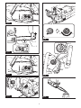
►Fig.1
• Do not overreach and do not cut above
shoulder height. This helps prevent unin-
tended tip contact and enables better control
of the chain saw in unexpected situations.
• Only use replacement guide bars and saw
chains specied by the manufacturer.
Incorrect replacement guide bars and saw
chains may cause chain breakage and/or
kickback.
• Follow the manufacturer’s sharpening
and maintenance instructions for the saw
chain. Decreasing the depth gauge height
can lead to increased kickback.
14. Follow all instructions when clearing jammed
material, storing or servicing the chain saw.
Make sure the switch is o and the battery
pack is removed. Unexpected actuation of the
chainsawwhileclearingjammedmaterialor
servicingmayresultinseriouspersonalinjury.
Additional Safety Instructions
Personal protective equipment
1. Clothing must be close-tting, but must not
obstruct mobility.
2.
Wear the following protective clothing during work:
• A tested safety helmet, if a hazard is pre-
sented by falling branches or similar;
• A face mask or goggles;
• Suitableearprotection(earmus,customor
mouldable ear plugs). Octave brand analysis
upon request.
• Firm leather safety gloves;
•
Long trousers manufactured from strong fabric;
• Protective dungarees of cut-resistant fabric;
• Safety shoes or boots with non-slip soles,
steel toes, and cut-resistant fabric lining;
• A breathing mask, when carrying out work
which produces dust (e.g. sawing dry wood).
Operation
1. Before starting work, check that the chain
saw is in proper working order and that its
condition complies with the safety regulations.
Check in particular that:
• The chain brake is working properly;
• The run-down brake is working properly;
•
Thebarandthesprocketcoverarettedcorrectly;
• The chain has been sharpened and ten-
sioned in accordance with the regulations.
2.
Do not start the chain saw with the chain cover
being installed on it. Starting the chain saw with the
chain cover being installed on it may cause the chain
cover to thrown out forward resulting in personal
injuryanddamagetoobjectsaroundtheoperator.
3.
When you use the tool on muddy ground, wet slope,
or slippery place, pay attention to your footing.
4. Do not submerge the tool into a puddle.
5. Do not leave the tool unattended outdoors in
the rain.
Electrical and battery safety
1. Avoid dangerous environment. Don't use the
tool in dump or wet locations or expose it to
rain. Water entering the tool will increase the risk
of electric shock.
2. Do not dispose of the battery(ies) in a re.
The cell may explode. Check with local codes for
possible special disposal instructions.
3. Do not open or mutilate the battery(ies).
Released electrolyte is corrosive and may cause
damage to the eyes or skin. It may be toxic if
swallowed.
4. Do not charge battery in rain, or in wet
locations.
5. Do not charge the battery outdoors.
6. Do not handle charger, including charger plug,
and charger terminals with wet hands.
7. Do not replace the battery in the rain.
8. Do not replace the battery with wet hands.
9. Do not leave the battery in the rain, nor charge,
use, or store the battery in a damp or wet
place.

13 ENGLISH
10. Do not wet the terminal of battery with liquid
such as water, or submerge the battery. If the
terminal gets wet or liquid enters inside of battery,
the battery may be short circuited and there is a
riskofoverheat,re,orexplosion.
11. After removing the battery from the machine or
charger, be sure to attach the battery cover to
the battery and store it in a dry place.
12. If the battery cartridge gets wet, drain the
water inside and then wipe it with a dry cloth.
Dry the battery cartridge completely in a dry
place before use.
Maintenance and storage
1. When storing the tool, avoid direct sunlight
and rain, and store it in a place where it does
not get hot or humid.
SAVE THESE INSTRUCTIONS.
WARNING: DO NOT let comfort or familiarity
with product (gained from repeated use) replace
strict adherence to safety rules for the subject
product. MISUSE or failure to follow the safety
rules stated in this instruction manual may cause
serious personal injury.
Important safety instructions for
battery cartridge
1.
Before using battery cartridge, read all instruc-
tions and cautionary markings on (1) battery char-
ger, (2) battery, and (3) product using battery.
2.
Do not disassemble or tamper with the battery car-
tridge.Itmayresultinare,excessiveheat,orexplosion.
3. If operating time has become excessively
shorter, stop operating immediately. It may
result in a risk of overheating, possible burns
and even an explosion.
4.
If electrolyte gets into your eyes, rinse them out
with clear water and seek medical attention right
away. It may result in loss of your eyesight.
5. Do not short the battery cartridge:
(1) Do not touch the terminals with any con-
ductive material.
(2) Avoid storing battery cartridge in a con-
tainer with other metal objects such as
nails, coins, etc.
(3) Do not expose battery cartridge to water
or rain.
A battery short can cause a large current
ow, overheating, possible burns and even a
breakdown.
6. Do not store and use the tool and battery car-
tridge in locations where the temperature may
reach or exceed 50 °C (122 °F).
7. Do not incinerate the battery cartridge even if
it is severely damaged or is completely worn
out. The battery cartridge can explode in a re.
8. Do not nail, cut, crush, throw, drop the battery
cartridge, or hit against a hard object to the
battery cartridge. Such conduct may result in a
re,excessiveheat,orexplosion.
9. Do not use a damaged battery.
10.
The contained lithium-ion batteries are subject to
the Dangerous Goods Legislation requirements.
For commercial transports e.g. by third parties,
forwarding agents, special requirement on pack-
aging and labeling must be observed.
For preparation of the item being shipped, consult-
ing an expert for hazardous material is required.
Please also observe possibly more detailed
national regulations.
Tapeormaskoopencontactsandpackupthe
battery in such a manner that it cannot move
around in the packaging.
11. When disposing the battery cartridge, remove
it from the tool and dispose of it in a safe
place. Follow your local regulations relating to
disposal of battery.
12. Use the batteries only with the products
specied by Makita. Installing the batteries to
non-compliantproductsmayresultinare,exces-
sive heat, explosion, or leak of electrolyte.
13. If the tool is not used for a long period of time,
the battery must be removed from the tool.
14. During and after use, the battery cartridge may
take on heat which can cause burns or low
temperature burns. Pay attention to the han-
dling of hot battery cartridges.
15. Do not touch the terminal of the tool imme-
diately after use as it may get hot enough to
cause burns.
16. Do not allow chips, dust, or soil stuck into the
terminals, holes, and grooves of the battery
cartridge.Itmaycauseheating,catchingre,
burst and malfunction of the tool or battery car-
tridge,resultinginburnsorpersonalinjury.
17. Unless the tool supports the use near
high-voltage electrical power lines, do not use
the battery cartridge near a high-voltage elec-
trical power lines. It may result in a malfunction
or breakdown of the tool or battery cartridge.
18. Keep the battery away from children.
SAVE THESE INSTRUCTIONS.
CAUTION: Only use genuine Makita batteries.
Use of non-genuine Makita batteries, or batteries that
have been altered, may result in the battery bursting
causingres,personalinjuryanddamage.Itwill
also void the Makita warranty for the Makita tool and
charger.
Tips for maintaining maximum
battery life
1. Charge the battery cartridge before completely
discharged. Always stop tool operation and
charge the battery cartridge when you notice
less tool power.
2.
Never recharge a fully charged battery cartridge.
Overcharging shortens the battery service life.
3.
Charge the battery cartridge with room tempera-
ture at 10 °C - 40 °C (50 °F - 104 °F). Let a hot
battery cartridge cool down before charging it.
4. When not using the battery cartridge, remove
it from the tool or the charger.
5. Charge the battery cartridge if you do not use
it for a long period (more than six months).

14 ENGLISH
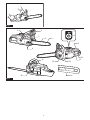
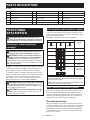
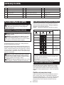
PARTS DESCRIPTION
►Fig.2
1Battery cartridge 2Front hand guard 3Chainadjustingscrew
4Guide bar 5Saw chain 6Retaining nut
7Main power lamp 8Main power switch 9Lock-olever
10 Rear handle 11 Switch trigger 12 Front handle
13 Oil tank cap 14 Guide bar cover 15 Adjustingscrew(foroilpump)
16 Chain catcher ----
FUNCTIONAL
DESCRIPTION
CAUTION: Always be sure that the tool is
switched o and the battery cartridge is removed
before adjusting or checking function on the tool.
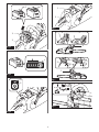
Installing or removing battery
cartridge
CAUTION: Always switch o the tool before
installing or removing of the battery cartridge.
CAUTION: Hold the tool and the battery car-
tridge rmly when installing or removing battery
cartridge. Failure to hold the tool and the battery
cartridgermlymaycausethemtoslipoyourhands
and result in damage to the tool and battery cartridge
andapersonalinjury.
►Fig.3: 1. Red indicator 2. Button 3. Battery cartridge
To remove the battery cartridge, slide it from the tool
while sliding the button on the front of the cartridge.
To install the battery cartridge, align the tongue on the
battery cartridge with the groove in the housing and slip
it into place. Insert it all the way until it locks in place
with a little click. If you can see the red indicator as
showninthegure,itisnotlockedcompletely.
CAUTION: Always install the battery cartridge
fully until the red indicator cannot be seen. If not,
itmayaccidentallyfalloutofthetool,causinginjuryto
you or someone around you.
CAUTION: Do not install the battery cartridge
forcibly. If the cartridge does not slide in easily, it is
not being inserted correctly.
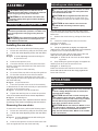
Indicating the remaining battery capacity
Press the check button on the battery cartridge to indi-
cate the remaining battery capacity. The indicator lamps
light up for a few seconds.
►Fig.4: 1. Indicator lamps 2. Check button
Indicator lamps Remaining
capacity
Lighted O Blinking
75% to 100%
50% to 75%
25% to 50%
0% to 25%
Charge the
battery.
The battery
may have
malfunctioned.
NOTE: Depending on the conditions of use and the
ambienttemperature,theindicationmaydierslightly
from the actual capacity.
NOTE:Therst(farleft)indicatorlampwillblinkwhen
the battery protection system works.
Tool / battery protection system
The tool is equipped with a tool/battery protection sys-
tem.Thissystemautomaticallycutsopowertothe
motor to extend tool and battery life. The tool will auto-
matically stop during operation if the tool or battery is
placed under one of the following conditions:
Overload protection
When the battery is operated in a manner that causes
it to draw an abnormally high current, the tool automati-
cally stops and the main power lamp blinks in green. In
thissituation,turnthetooloandstoptheapplication
that caused the tool to become overloaded. Then turn
the tool on to restart.

15 ENGLISH
Overheat protection
When the tool or battery is overheated, the tool stops
automatically and the main power lamp lights up in red.
In this case, let the tool and battery cool before turning
the tool on again.
NOTE: In high temperature environment, the over-
heat protection likely to work and the tool stops
automatically.
Overdischarge protection
When the battery capacity is not enough, the tool stops
automatically and the main power lamp blinks in red. In
this case, remove the battery from the tool and charge
the battery.
Protections against other causes
Protection system is also designed for other causes
that could damage the tool and allows the tool to stop
automatically. Take all the following steps to clear the
causes, when the tool has been brought to a temporary
halt or stop in operation.
1. Turnthetoolo,andthenturnitonagainto
restart.
2. Charge the battery(ies) or replace it/them with
recharged battery(ies).
3. Let the machine and battery(ies) cool down.
If no improvement can be found by restoring protection
system, then contact your local Makita Service Center.
NOTICE: If the tool stops due to a cause
not described above, refer to the section for
troubleshooting.
Main power switch
WARNING: Always turn o the main power
switch when not in use.
To turn on the tool, press the main power switch. The
mainpowerlamplightsupingreen.Toturno,press
the main power switch again.
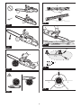
►Fig.5: 1. Main power lamp 2. Main power switch
NOTE: The main power lamp blinks in green if the
switch trigger is pulled under unoperatable conditions.
The lamp blinks in one of the following conditions.
• When you turn on the main power switch while
holdingdownthelock-oleverandtheswitch
trigger.
• When you pull the switch trigger while the chain
brake is applied.
• When you release the chain brake while holding
downthelock-oleverandpullingtheswitch
trigger.
NOTE:Thistoolemploystheautopower-ofunction.
To avoid unintentional start up, the main power switch
will automatically shut down when the switch trigger
is not pulled for a certain period after the main power
switch is turned on.
Switch action
WARNING: For your safety, this tool is
equipped with lock-o lever which prevents the
tool from unintended starting. NEVER use the tool
if it runs when you simply pull the switch trigger
without pressing the lock-o lever. Return the
tool to our authorized service center for proper
repairs BEFORE further usage.
WARNING: NEVER tape down or defeat pur-
pose and function of lock-o lever.
CAUTION: Before installing the battery car-
tridge into the tool, always check to see that the
switch trigger actuates properly and returns to
the "OFF" position when released.
NOTICE: Do not pull the switch trigger hard with-
out pressing the lock-o lever. This can cause
switch breakage.
To prevent the switch trigger from being accidentally
pulled,alock-oleverisprovided.Tostartthetool,
depressthelock-oleverandpulltheswitchtrigger.
Tool speed is increased by increasing pressure on the
switch trigger. Release the switch trigger to stop.
►Fig.6: 1. Switch trigger 2.Lock-olever
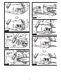
Checking the chain brake
CAUTION: Hold the chain saw with both
hands when switching it on. Hold the rear handle
with your right hand, the front handle with your
left. The bar and the chain must not be in contact
with any object.
CAUTION: Should the saw chain not stop
immediately when this test is performed, the
saw may not be used under any circumstances.
Consult our authorized service center.
1. Pressthelock-olever,thenpulltheswitchtrig-
ger. The saw chain starts immediately.
2. Push the front hand guard forwards with the back
of your hand. Make sure that the chain saw comes to an
immediate standstill.
►Fig.7: 1. Front hand guard 2. Unlocked position
3. Locked position
Checking the run-down brake
CAUTION: If the saw chain does not stop
within one second in this test, stop using the
chain saw and consult our authorized service
center.
Run the chain saw then release the switch trigger completely.
The saw chain must come to a standstill within one second.
Adjusting the chain lubrication
Youcanadjusttheoilpumpfeedratewiththeadjusting
screw.Theamountofoilcanbeadjustedusingthe
universal wrench.
►Fig.8: 1.Adjustingscrew

16 ENGLISH
ASSEMBLY
CAUTION: Always be sure that the tool is
switched o and the battery cartridge is removed
before carrying out any work on the tool.
CAUTION: Do not touch the saw chain with
bare hands. Always wear gloves when handling
the saw chain.
Installing or removing saw chain
CAUTION: The saw chain and the guide bar
are still hot just after the operation. Let them cool
down enough before carrying out any work on
the tool.
CAUTION: Carry out the procedure of install-
ing or removing saw chain in a clean place free
from sawdust and the like.
Installing the saw chain
To install the saw chain, perform the following steps:
1.
Release the chain brake by pulling the front hand guard.
2. Loosenthechainadjustingscrew,thentheretain-
ing nuts.
►Fig.9: 1.Chainadjustingscrew2. Retaining nut
3. Sprocket cover
3. Remove the sprocket cover.
4. Check the direction of the saw chain. Match the
direction of the saw chain with that of the mark on the
chain saw body.
►Fig.10: 1. Mark on chain saw body
5.
Fit one end of the saw chain on the top of the guide bar.
6. Fit the other end of the saw chain around the
sprocket, then attach the guide bar to the chain saw
body, aligning the hole on the guide bar with the pin on
the chain saw body.
►Fig.11: 1. Sprocket 2. Hole
7. Place the sprocket cover on the chain saw body
so that the bolts on the chain saw body are positioned in
the holes on the sprocket cover.
►Fig.12: 1. Sprocket cover 2. Hole 3. Bolt
8. Tighten the retaining nuts to secure the sprocket
cover,thenloosenthemabitfortensionadjustment.
►Fig.13: 1. Retaining nut
Afterinstallingthesawchain,adjustthesawchaintension
byreferringtothesectionforadjustingsawchaintension.
Removing the saw chain
To remove the saw chain, perform the following steps:
1.
Release the chain brake by pulling the front hand guard.
2. Loosenthechainadjustingscrew,thentheretain-
ing nuts.
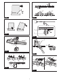
►Fig.14: 1.Chainadjustingscrew2. Retaining nut
3. Sprocket cover
3. Remove the sprocket cover then remove the saw
chain and guide bar from the chain saw body.
Adjusting saw chain tension
CAUTION: Carry out the procedure of install-
ing or removing saw chain in a clean place free
from sawdust and the like.
CAUTION: Do not tighten the saw chain too
much. Excessively high tension of saw chain may
cause breakage of saw chain and wear of the guide
bar.
CAUTION: A chain which is too loose can
jump o the bar and it may cause an injury
accident.
The saw chain may become loose after many hours
of use. From time to time check the saw chain tension
before use.
1. Release the chain brake by pulling the front hand
guard.
2. Loosen the retaining nuts a bit to loosen the
sprocket cover lightly.
►Fig.15: 1. Retaining nut
3. Liftuptheguidebartipslightlyandadjustthe
chaintension.Turnthechainadjustingscrewclockwise
to tighten, turn it counterclockwise to loosen.
Tighten the saw chain until the lower side of the saw
chaintsintheguidebarrailasillustrated.
►Fig.16: 1. Guide bar 2. Saw chain 3.Chainadjust-
ing screw
4. Keep holding the guide bar lightly and tighten the
retaining nuts to secure the sprocket cover.
►Fig.17: 1. Retaining nut
Make sure that the saw chain does not loose at the
lowersideandthesawchaintssnuglyagainstthe
lower side of the bar.
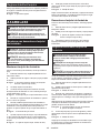
OPERATION
Lubrication
CAUTION: Do not operate the chain saw when
the tank is empty. Replenish the oil in due time
before the tank is empty.
CAUTION: Prevent the oil from coming into
contact with the skin and eyes. Contact with the
eyes causes irritation. In the event of eye contact,
ush the aected eye immediately with clear
water, then consult a doctor at once.
CAUTION: Never use waste oil. Waste oil con-
tains carcinogenic substances. The contaminants
in waste oil cause accelerated wear of the oil
pump, the bar and the chain. Waste oil is harmful
to the environment.

17 ENGLISH
NOTICE: When the chain saw is used for the rst
time, it may take up to two minutes for the saw
chain oil to begin its lubricating eect upon the
saw mechanism. Run the saw without load until
it does so.
NOTICE: When lling the chain oil for the rst
time, or relling the tank after it has been com-
pletely emptied, add oil up to the bottom edge of
the ller neck. The oil delivery may otherwise be
impaired.
NOTICE: Use the saw chain oil exclusively for
Makita chain saws or equivalent oil available in
the market.
NOTICE: Never use oil including dust and parti-
cles or volatile oil.
NOTICE: When pruning trees, use botanical oil.
Mineral oil may harm trees.
NOTICE: Before the cutting operation, make sure
that the provided oil tank cap is screwed in place.
Saw chain is automatically lubricated when the tool is in
operation. Check the amount of remaining oil in the oil
tank periodically through the oil inspection window.
►Fig.18: 1. Oil tank cap 2. Oil inspection window
Tolltheoil,performthefollowingsteps:
1. Clean the area around the oil tank cap thoroughly
to prevent any dirt from entering the oil tank.
2. Lay the chain saw on its side.
3. Push the button on the oil tank cap so that the
button on the other side stands up, and then remove the
oil tank cap by turning it.
►Fig.19: 1. Oil tank cap 2. Tighten 3. Loosen
4. Fill the oil tank with the oil. The proper amount of
oil is 260 ml.
5. Screwtheoiltankcaprmlybackinplace.
6. Wipe away any spilt chain oil carefully.
NOTE:Ifitisdiculttoremovetheoiltankcap,
insert the box wrench into the slot of the oil tank
cap, and then remove the oil tank cap by turning it
counterclockwise.
►Fig.20: 1. Slot 2. Box wrench
Afterrelling,holdthechainsawawayfromthe
tree. Start it and wait until lubrication on saw chain is
adequate.
►Fig.21
Working with the chain saw
CAUTION: The rst time user should, as a
minimum practice, do cutting logs on a saw-horse
or cradle.
CAUTION: When sawing precut timber, use a
safe support (saw horse or cradle). Do not steady
the workpiece with your foot, and do not allow
anyone else to hold or steady it.
CAUTION: Secure round pieces against
rotation.
CAUTION: Keep all parts of the body away
from the saw chain when the motor is operating.
CAUTION: Hold the chain saw rmly with
both hands when the motor is running.
CAUTION: Do not overreach. Keep proper
footing and balance at all times.
NOTICE: Never toss or drop the tool.
NOTICE: Do not cover the vents of the tool.
Bring the bottom edge of the chain saw body into
contact with the branch to be cut before switching on.
Otherwise it may cause the guide bar to wobble, result-
ingininjurytooperator.Sawthewoodtobecutbyjust
moving it down by using the weight of the chain saw.
►Fig.22
If you cannot cut the timber right through with a single
stroke:
Apply light pressure to the handle and continue sawing
and draw the chain saw back a little; then apply the
spikebumperalittlelowerandnishthecutbyraising
the handle.
►Fig.23
Bucking
1. Rest the bottom edge of the chain saw body on
the wood to be cut.
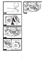
►Fig.24
2. With the saw chain running, saw into the wood
while using the rear handle to raise the saw and the
front one to guide it. Use the spike bumper as a pivot.
3. Continue the cut by applying slight pressure to
the front handle, easing the saw back slightly. Move
the spike bumper further down the timber and raise the
front handle again.
NOTICE: When making several cuts, switch the
chain saw o between cuts.
CAUTION: If the upper edge of the bar is used
for cutting, the chain saw may be deected in
your direction if the chain becomes trapped. For
this reason, cut with the lower edge, so that the
saw will be deected away from your body.
►Fig.25
When you cut a wood under tension, cut the pressured
side(A)rst.Thenmakethenalcutfromthetensioned
side (B). This prevents the bar from becoming trapped.
►Fig.26

18 ENGLISH
Limbing
CAUTION: Limbing may only be performed by
trained persons. A hazard is presented by the risk
of kickback.
When limbing, support the chain saw on the trunk if
possible. Do not cut with the tip of the bar, as this pres-
ents a risk of kickback.
Pay particular attention to branches under tension. Do
not cut unsupported branches from below.
Do not stand on the felled trunk when limbing.
Burrowing and parallel-to-grain cuts
CAUTION:
Burrowing and parallel-to-grain cuts
may only be carried out by persons with special train-
ing.Thepossibilityofkickbackpresentsariskofinjury.
Perform parallel-to-grain cuts at as shallow an angle as
possible. Take an extra caution when carrying out the
cut as the spike bumper cannot be used.
►Fig.27
Felling
CAUTION: Felling work may only be per-
formed by trained persons. The work is hazardous.
Observe local regulations if you wish to fell a tree.
►Fig.28: 1. Felling area
— Before starting felling work, ensure that:
• Only persons involved in the felling operation
are in the vicinity;
•
Any person involved has an unhindered path
of retreat through a range of approximately
45° either side of the felling axis. Consider the
additional risk of tripping over electrical cables;
• The base of the trunk is free of foreign
objects,rootsandranches;
• Nopersonsorobjectsarepresentovera
distance of 2 1/2 tree lengths in the direction
in which the tree will fall.
— Consider the following with respect to each tree:
• Direction of lean;
• Loose or dry branches;
• Height of the tree;
• Natural overhang;
• Whether or not the tree is rotten.
— Consider the wind speed and direction. Do not
carry out felling work if the wind is gusting strongly.
— Trimming of root swellings: Begin with the largest
swellings.Maketheverticalcutrst,thenthe
horizontal cut.
— Stand to the side of the falling tree. Keep an area
clear to the rear of the falling tree up to an angle of
45° either side of the tree axis (refer to the “felling
area”gure).Payattentiontofallingbranches.
— An escape path should be planned and cleared
as necessary before cuts are started. The escape
path should extend back and diagonally to the rear
oftheexpectedlineoffallasillustratedingure.
►Fig.29: 1. Felling direction 2. Danger zone
3. Escape route
When felling trees, follow the procedures below:
1. Cut a scarf as close to the ground as possible.
First make the horizontal cut to a depth of 1/5 -1/3 of the
trunk diameter. Do not make the scarf too large. Then
make the diagonal cut.
►Fig.30
NOTE: The scarf determines the direction in which
the tree will fall, and guides it. It is made on the side
towards which the tree is to fall.
2.
Make the back cut a little higher than the base cut of
the scarf. The back cut must be exactly horizontal. Leave
approximately 1/10 of the trunk diameter between the back
cutandthescarf.Thewoodbersintheuncuttrunkportion
act as a hinge. Insert wedges into the back cut in time.
►Fig.31
WARNING: Do not cut right through the bers
under any circumstances. The tree will otherwise
fall unchecked.
NOTICE: Only plastic or aluminum wedges may
be used to keep the back cut open. The use of
iron wedges is prohibited.
Carrying tool
Before carrying the tool, always apply the chain brake
and remove the battery cartridge from the tool. Then
attach the guide bar cover. Also cover the battery car-
tridge with the battery cover.
►Fig.32: 1. Guide bar cover 2. Battery cover
MAINTENANCE
CAUTION: Always be sure that the tool is
switched o and the battery cartridge is removed
before attempting to perform inspection or
maintenance.
CAUTION: Always wear gloves when perform-
ing any inspection or maintenance.
NOTICE: Never use gasoline, benzine, thinner,
alcohol or the like. Discoloration, deformation or
cracks may result.
To maintain product SAFETY and RELIABILITY,
repairs,anyothermaintenanceoradjustmentshould
be performed by Makita Authorized or Factory Service
Centers, always using Makita replacement parts.
Sharpening the saw chain
Sharpen the saw chain when:
• Mealy sawdust is produced when damp wood is
cut;
• Thechainpenetratesthewoodwithdiculty,even
when heavy pressure is applied;
• The cutting edge is obviously damaged;
• The saw pulls to the left or right in the wood.
(caused by uneven sharpening of the saw chain or
damage to one side only)

19 ENGLISH
Sharpen the saw chain frequently but a little each time. Two
orthreestrokeswithaleareusuallysucientforroutine
resharpening. When the saw chain has been resharpened sev-
eral times, have it sharpened in our authorized service center.
Sharpening criteria:
WARNING: An excessive distance between
the cutting edge and depth gauge increases the
risk of kickback.
►Fig.33: 1. Cutter length 2. Distance between cutting
edge and depth gauge 3. Minimum cutter
length (3 mm)
— Allcutterlengthmustbeequal.Dierentcutter
lengths prevent the saw chain from running
smoothly and may cause the saw chain to break.
— Do not sharpen the chain when the cutter length
has reached 3 mm or shorter. The chain must be
replaced with new one.
—
The chip thickness is determined by the distance between
the depth gauge (round nose) and the cutting edge.
— The best cutting results are obtained with following
distance between cutting edge and depth gauge.
• Chain blade 91PX : 0.65 mm
• Chain blade 80TXL : 0.65 mm
►Fig.34
— The sharpening angle of 30° must be the same on
allcutters.Dierentcutteranglescausethechain
to run roughly and unevenly, accelerate wear, and
lead to chain breaks.
— Useasuitableroundlesothatthepropersharp-
ening angle is kept against the teeth.
• Chain blade 91PX : 55°
• Chain blade 80TXL : 55°
File and le guiding
— Useaspecialroundle(optionalaccessory)for
saw chains to sharpen the chain. Normal round
lesarenotsuitable.
—
Diameteroftheroundleforeachsawchainisasfollows:
• Chain blade 91PX : 4.0 mm
• Chain blade 80TXL : 4.0 mm
— Theleshouldonlyengagethecutteronthefor-
wardstroke.Lifttheleothecutteronthereturn
stroke.
— Sharpentheshortestcutterrst.Thenthelength
of this shortest cutter becomes the standard for all
other cutters on the saw chain.
— Guidetheleasshowninthegure.
►Fig.35: 1. File 2. Saw chain
— Thelecanbeguidedmoreeasilyifaleholder
(optionalaccessory)isemployed.Theleholder
has markings for the correct sharpening angle of
30° (align the markings parallel to the saw chain)
and limits the depth of penetration (to 4/5 of the
lediameter).
►Fig.36: 1. File holder
—
After sharpening the chain, check the height of the depth
gauge using the chain gauge tool (optional accessory).
►Fig.37
— Removeanyprojectingmaterial,howeversmall,
withaspecialatle(optionalaccessory).
— Roundothefrontofthedepthgaugeagain.
Cleaning the guide bar
Chips and sawdust will build up in the guide bar groove.
Theymayclogthebargrooveandimpairtheoilow.
Clean out the chips and sawdust every time when you
sharpen or replace the saw chain.
►Fig.38
Cleaning the sprocket cover
Chips and saw dust will accumulate inside of the
sprocket cover. Remove the sprocket cover and saw
chain from the tool then clean the chips and saw dust.
►Fig.39
Cleaning the oil discharge hole
Small dust or particles may be built up in the oil dis-
charge hole during operation. These dust or particles
mayimpairtheoiltoowandcauseaninsucient
lubrication on the whole saw chain. When a poor chain
oil delivery occurs at the top of guide bar, clean the oil
discharge hole as follows.
1. Remove the sprocket cover and saw chain from
the tool.
2. Remove the small dust or particles using a slotted
screwdriver or the like.
►Fig.40: 1. Slotted screwdriver 2. Oil discharge hole
3. Insert the battery cartridge into the tool. Pull the
switchtriggertoowbuilt-updustorparticlesotheoil
discharge hole by discharging chain oil.
4. Remove the battery cartridge from the tool.
Reinstall the sprocket cover and saw chain on the tool.
Replacing the sprocket
CAUTION: A worn sprocket will damage a
new saw chain. Have the sprocket replaced in this
case.
Beforettinganewsawchain,checktheconditionof
the sprocket.
►Fig.41: 1. Sprocket 2. Areas to be worn out
Alwaystanewlockingringwhenreplacingthe
sprocket.
►Fig.42: 1. Locking ring 2. Sprocket
NOTICE: Make sure that the sprocket is installed
as shown in the gure.
Storing the tool
1. Clean the tool before storing. Remove any chips
and sawdust from the tool after removing the sprocket
cover.
2. After cleaning the tool, run it under no load to lubri-
cate the saw chain and guide bar.
3. Cover the guide bar with the guide bar cover.
4. Empty the oil tank.

20 ENGLISH
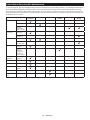
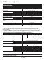
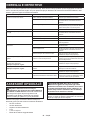
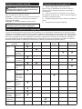
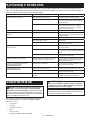
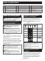
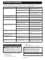
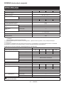
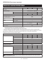
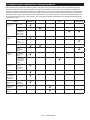
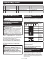
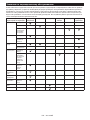
Instructions for periodic maintenance
To ensure long life, prevent damage and ensure the full functioning of the safety features, the following maintenance
must be performed regularly. Warranty claims can be recognized only if this work is performed regularly and prop-
erly. Failure to perform the prescribed maintenance work can lead to accidents! The user of the chain saw must not
perform maintenance work which is not described in the instruction manual. All such work must be carried out by our
authorized service center.
Check item / Operating time Before
operation Everyday Every week Every 3
month Annually Before
storage
Chain saw Inspection. -----
Cleaning. -----
Check at
authorized
service center.
----
Saw chain Inspection. -----
Sharpening if
necessary. -----
Guide bar Inspection. ----
Remove from
the chain saw. -----
Chain brake Check the
function. -----
Have it
inspected
regularly at
authorized
service center.
--- - -
Chain
lubrication Check the oil
feed rate. -----
Switch trigger Inspection. -----
Lock-olever Inspection. -----
Oil tank cap Check
tightness. -----
Chain catcher Inspection. - - ---
Screws and
nuts Inspection. - - ---
Pagina se încarcă...
Pagina se încarcă...
Pagina se încarcă...
Pagina se încarcă...
Pagina se încarcă...
Pagina se încarcă...
Pagina se încarcă...
Pagina se încarcă...
Pagina se încarcă...
Pagina se încarcă...
Pagina se încarcă...
Pagina se încarcă...
Pagina se încarcă...
Pagina se încarcă...
Pagina se încarcă...
Pagina se încarcă...
Pagina se încarcă...
Pagina se încarcă...
Pagina se încarcă...
Pagina se încarcă...
Pagina se încarcă...
Pagina se încarcă...
Pagina se încarcă...
Pagina se încarcă...
Pagina se încarcă...
Pagina se încarcă...
Pagina se încarcă...
Pagina se încarcă...
Pagina se încarcă...
Pagina se încarcă...
Pagina se încarcă...
Pagina se încarcă...
Pagina se încarcă...
Pagina se încarcă...
Pagina se încarcă...
Pagina se încarcă...
Pagina se încarcă...
Pagina se încarcă...
Pagina se încarcă...
Pagina se încarcă...
Pagina se încarcă...
Pagina se încarcă...
Pagina se încarcă...
Pagina se încarcă...
Pagina se încarcă...
Pagina se încarcă...
Pagina se încarcă...
Pagina se încarcă...
Pagina se încarcă...
Pagina se încarcă...
Pagina se încarcă...
Pagina se încarcă...
Pagina se încarcă...
Pagina se încarcă...
Pagina se încarcă...
Pagina se încarcă...
Pagina se încarcă...
Pagina se încarcă...
Pagina se încarcă...
Pagina se încarcă...
Pagina se încarcă...
Pagina se încarcă...
Pagina se încarcă...
Pagina se încarcă...
Pagina se încarcă...
Pagina se încarcă...
Pagina se încarcă...
Pagina se încarcă...
Pagina se încarcă...
Pagina se încarcă...
Pagina se încarcă...
Pagina se încarcă...
Pagina se încarcă...
Pagina se încarcă...
Pagina se încarcă...
Pagina se încarcă...
Pagina se încarcă...
Pagina se încarcă...
Pagina se încarcă...
Pagina se încarcă...
Pagina se încarcă...
Pagina se încarcă...
Pagina se încarcă...
Pagina se încarcă...
Pagina se încarcă...
Pagina se încarcă...
Pagina se încarcă...
Pagina se încarcă...
Pagina se încarcă...
Pagina se încarcă...
Pagina se încarcă...
Pagina se încarcă...
Pagina se încarcă...
Pagina se încarcă...
Pagina se încarcă...
Pagina se încarcă...
Pagina se încarcă...
Pagina se încarcă...
Pagina se încarcă...
Pagina se încarcă...
Pagina se încarcă...
Pagina se încarcă...
Pagina se încarcă...
Pagina se încarcă...
Pagina se încarcă...
Pagina se încarcă...
Pagina se încarcă...
Pagina se încarcă...
Pagina se încarcă...
Pagina se încarcă...
Pagina se încarcă...
Pagina se încarcă...
Pagina se încarcă...
Pagina se încarcă...
Pagina se încarcă...
Pagina se încarcă...
Pagina se încarcă...
Pagina se încarcă...
Pagina se încarcă...
Pagina se încarcă...
Pagina se încarcă...
Pagina se încarcă...
Pagina se încarcă...
Pagina se încarcă...
Pagina se încarcă...
Pagina se încarcă...
Pagina se încarcă...
Pagina se încarcă...
Pagina se încarcă...
Pagina se încarcă...
Pagina se încarcă...
Pagina se încarcă...
-
 1
1
-
 2
2
-
 3
3
-
 4
4
-
 5
5
-
 6
6
-
 7
7
-
 8
8
-
 9
9
-
 10
10
-
 11
11
-
 12
12
-
 13
13
-
 14
14
-
 15
15
-
 16
16
-
 17
17
-
 18
18
-
 19
19
-
 20
20
-
 21
21
-
 22
22
-
 23
23
-
 24
24
-
 25
25
-
 26
26
-
 27
27
-
 28
28
-
 29
29
-
 30
30
-
 31
31
-
 32
32
-
 33
33
-
 34
34
-
 35
35
-
 36
36
-
 37
37
-
 38
38
-
 39
39
-
 40
40
-
 41
41
-
 42
42
-
 43
43
-
 44
44
-
 45
45
-
 46
46
-
 47
47
-
 48
48
-
 49
49
-
 50
50
-
 51
51
-
 52
52
-
 53
53
-
 54
54
-
 55
55
-
 56
56
-
 57
57
-
 58
58
-
 59
59
-
 60
60
-
 61
61
-
 62
62
-
 63
63
-
 64
64
-
 65
65
-
 66
66
-
 67
67
-
 68
68
-
 69
69
-
 70
70
-
 71
71
-
 72
72
-
 73
73
-
 74
74
-
 75
75
-
 76
76
-
 77
77
-
 78
78
-
 79
79
-
 80
80
-
 81
81
-
 82
82
-
 83
83
-
 84
84
-
 85
85
-
 86
86
-
 87
87
-
 88
88
-
 89
89
-
 90
90
-
 91
91
-
 92
92
-
 93
93
-
 94
94
-
 95
95
-
 96
96
-
 97
97
-
 98
98
-
 99
99
-
 100
100
-
 101
101
-
 102
102
-
 103
103
-
 104
104
-
 105
105
-
 106
106
-
 107
107
-
 108
108
-
 109
109
-
 110
110
-
 111
111
-
 112
112
-
 113
113
-
 114
114
-
 115
115
-
 116
116
-
 117
117
-
 118
118
-
 119
119
-
 120
120
-
 121
121
-
 122
122
-
 123
123
-
 124
124
-
 125
125
-
 126
126
-
 127
127
-
 128
128
-
 129
129
-
 130
130
-
 131
131
-
 132
132
-
 133
133
-
 134
134
-
 135
135
-
 136
136
-
 137
137
-
 138
138
-
 139
139
-
 140
140
-
 141
141
-
 142
142
-
 143
143
-
 144
144
-
 145
145
-
 146
146
-
 147
147
-
 148
148
-
 149
149
-
 150
150
-
 151
151
-
 152
152


Makita UC010G Cordless Chain Saw Manual de utilizare
- Categorie
- Ferăstraie cu lanț electric
- Tip
- Manual de utilizare
Lucrări înrudite
-
Makita BUC122 Manual de utilizare
-
Makita DUC305 Manual de utilizare
-
Makita DUC306 Manual de utilizare
-
Makita UA004GZ Manual de utilizare
-
-
-
Makita DUC101Z Manual de utilizare
-
-
Makita UC4020A Manual de utilizare
-
Makita DCS232T Manual de utilizare
Alte documente
-
Hikoki CS3630DC Manual de utilizare
-
Hikoki CS1825DC Manual de utilizare
-
 EGO Power CS1610E Manual de utilizare
-
EGO CS1804 Manual de utilizare
-
GGP ITALY CS 24 Li Instrucțiuni de utilizare
-
Alpina Garden MT24Li Instrucțiuni de utilizare
-
Raider Garden Tools RD-GCS19 Manual de utilizare
-
-
Worx EC-P115 Manualul proprietarului
-
Hikoki DH 36DL Manual de utilizare
