Makita HS012G Cordless Circular Saw Manual de utilizare
- Tip
- Manual de utilizare

HS012G
EN Cordless Circular Saw INSTRUCTION MANUAL 9
SL Brezžična krožna žaga NAVODILA ZA UPORABO 22
SQ Sharrë e rrumbullakët me
bateri MANUALI I PËRDORIMIT 35
BG Акумулаторен циркуляр РЪКОВОДСТВО ЗА
ЕКСПЛОАТАЦИЯ 49
HR Bežična kružna pila PRIRUČNIK S UPUTAMA 65
МК Безжична циркуларна пила УПАТСТВО ЗА УПОТРЕБА 78
SR Бежична циркуларна
тестера УПУТСТВО ЗА УПОТРЕБУ 94
RO Ferăstrău circular cu
acumulator MANUAL DE INSTRUCŢIUNI 108
UK Бездротова циркулярна
пила ІНСТРУКЦІЯ З
ЕКСПЛУАТАЦІЇ 122
RU Аккумуляторная
циркулярная пила РУКОВОДСТВО ПО
ЭКСПЛУАТАЦИИ 137

2
Fig.1
Fig.2
Fig.3
Fig.4
Fig.5
Fig.6

3
11
2
3
Fig.7
12
Fig.8
1
2
Fig.9
1
Fig.10
1
Fig.11
1
Fig.12

4
12
Fig.13
1
Fig.14
Fig.15
1
2
3
Fig.16
1
Fig.17
1
3
2
4
Fig.18
1
2
3
4
5
6
Fig.19

5
1
2
3
4
5
6
7
Fig.20
12
3
4
5
Fig.21
12
3
4
5
Fig.22
12
34
5
6
15.88
15.88
15.88
Fig.23
1
2
Fig.24
123
Fig.25
11
2
2
33
4
56
Fig.26

6
Fig.27
1
2
Fig.28
Fig.29
1
Fig.30
1
2
3
4
Fig.31
1
2
3
Fig.32
1
Fig.33

7
1
1
2
2
Fig.34
Fig.35
1
Fig.36
1
2
Fig.37
1
Fig.38
1
Fig.39

8
1
1
2
2
Fig.40
1
2
3
Fig.41
2
A
1
1
B
Fig.42

9ENGLISH
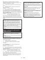
ENGLISH (Original instructions)
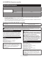
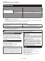
SPECIFICATIONS
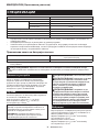
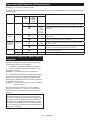
Model: HS012G
Blade diameter 165 mm
Max. Cutting depth at 0° 57 mm
at 45° bevel 41 mm
at 50° bevel 37 mm
No load speed 5,200 min-1
Rated voltage D.C. 36 V - 40 V max
Overall length (with BL4025) 352 mm
Net weight 3.2 - 4.4 kg
• Duetoourcontinuingprogramofresearchanddevelopment,thespecicationshereinaresubjecttochange
without notice.
• Specicationsmaydierfromcountrytocountry.
• Theweightmaydierdependingontheattachment(s),includingthebatterycartridge.Thelightestandheavi-
est combinations, according to EPTA-Procedure 01/2014, are shown in the table.
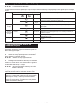
Applicable battery cartridge and charger
Batterycartridge BL4020* / BL4025* / BL4040* / BL4050F / BL4080F
*:Recommendedbattery
Charger DC40RA / DC40RB / DC40RC
• Someofthebatterycartridgesandchargerslistedabovemaynotbeavailabledependingonyourregionof
residence.
WARNING: Only use the battery cartridges and chargers listed above.Useofanyotherbatterycartridges
andchargersmaycauseinjuryand/orre.
Intended use
Thetoolisintendedforperforminglengthwaysand
crosswaysstraightcutsandmitercutswithanglesin
woodwhileinrmcontactwiththeworkpiece.With
appropriate Makita genuine saw blades, other materials
can also be sawed. For details, according to the section
for OPERATION.
Noise
ThetypicalA-weightednoiseleveldeterminedaccord-
ing to EN62841-2-5:
Sound pressure level (LpA) : 91 dB (A)
Sound power level (LWA) : 102 dB (A)
Uncertainty(K):3dB(A)
NOTE: The declared noise emission value(s) has
been measured in accordance with a standard test
methodandmaybeusedforcomparingonetoolwith
another.
NOTE: The declared noise emission value(s)
mayalsobeusedinapreliminaryassessmentof
exposure.
WARNING: Wear ear protection.
WARNING: The noise emission during actual
use of the power tool can dier from the declared
value(s) depending on the ways in which the
tool is used especially what kind of workpiece is
processed.
WARNING: Be sure to identify safety mea-
sures to protect the operator that are based on an
estimation of exposure in the actual conditions of
use (taking account of all parts of the operating
cycle such as the times when the tool is switched
o and when it is running idle in addition to the
trigger time).
Vibration
The vibration total value (tri-axial vector sum) deter-
mined according to EN62841-2-5:
Workmode:cuttingwood
Vibration emission (ah,W) : 2.5 m/s2 or less
Uncertainty(K):1.5m/s2
Workmode:cuttingmetal
Vibration emission (ah,W) : 2.5 m/s2 or less
Uncertainty(K):1.5m/s2

10 ENGLISH
NOTE: The declared vibration total value(s) has been
measured in accordance with a standard test method
andmaybeusedforcomparingonetoolwithanother.
NOTE:Thedeclaredvibrationtotalvalue(s)mayalso
beusedinapreliminaryassessmentofexposure.
WARNING: The vibration emission during
actual use of the power tool can dier from the
declared value(s) depending on the ways in which
the tool is used especially what kind of workpiece
is processed.
WARNING: Be sure to identify safety mea-
sures to protect the operator that are based on an
estimation of exposure in the actual conditions of
use (taking account of all parts of the operating
cycle such as the times when the tool is switched
o and when it is running idle in addition to the
trigger time).
EC Declaration of Conformity
For European countries only
TheECdeclarationofconformityisincludedasAnnexA
to this instruction manual.
SAFETY WARNINGS
General power tool safety warnings
WARNING Read all safety warnings, instruc-
tions, illustrations and specications provided with
this power tool. Failure to follow all instructions listed
belowmayresultinelectricshock,reand/orserious
injury.
Save all warnings and instruc-
tions for future reference.
Theterm"powertool"inthewarningsreferstoyour
mains-operated(corded)powertoolorbattery-operated
(cordless) power tool.
Cordless circular saw safety warnings
Cutting procedures
1. DANGER: Keep hands away from cutting
area and the blade. Keep your second hand
on auxiliary handle, or motor housing. If both
handsareholdingthesaw,theycannotbecutby
the blade.
2. Do not reach underneath the workpiece. The
guardcannotprotectyoufromthebladebelowthe
workpiece.
3. Adjust the cutting depth to the thickness of
the workpiece. Less than a full tooth of the blade
teeth should be visible below the workpiece.
4. Never hold the workpiece in your hands or
across your leg while cutting. Secure the
workpiece to a stable platform. It is important to
supporttheworkproperlytominimisebodyexpo-
sure, blade binding, or loss of control.
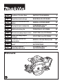
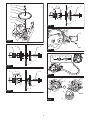
►Fig.1
5. Hold the power tool by insulated gripping
surfaces, when performing an operation where
the cutting tool may contact hidden wiring.
Contact with a “live” wire will also make exposed
metal parts of the power tool “live” and could give
the operator an electric shock.
6. When ripping, always use a rip fence or
straight edge guide.Thisimprovestheaccuracy
of cut and reduces the chance of blade binding.
7. Always use blades with correct size and shape
(diamond versus round) of arbour holes.
Blades that do not match the mounting hardware
ofthesawwillruno-centre,causinglossof
control.
8. Never use damaged or incorrect blade wash-
ers or bolt. The blade washers and bolt were
speciallydesignedforyoursaw,foroptimum
performanceandsafetyofoperation.
Kickback causes and related warnings
— kickback is a sudden reaction to a pinched,
jammedormisalignedsawblade,causingan
uncontrolled saw to lift up and out of the workpiece
toward the operator;
— whenthebladeispinchedorjammedtightlybythe
kerf closing down, the blade stalls and the motor
reactiondrivestheunitrapidlybacktowardthe
operator;
— if the blade becomes twisted or misaligned in the
cut, the teeth at the back edge of the blade can dig
into the top surface of the wood causing the blade
toclimboutofthekerfandjumpbacktowardthe
operator.
Kickbackistheresultofsawmisuseand/orincorrect
operating procedures or conditions and can be avoided
bytakingproperprecautionsasgivenbelow.
1. Maintain a rm grip with both hands on the
saw and position your arms to resist kickback
forces. Position your body to either side of the
blade, but not in line with the blade.Kickback
couldcausethesawtojumpbackwards,but
kickbackforcescanbecontrolledbytheoperator,
if proper precautions are taken.
2. When blade is binding, or when interrupting a
cut for any reason, release the trigger and hold
the saw motionless in the material until the
blade comes to a complete stop. Never attempt
to remove the saw from the work or pull the
saw backward while the blade is in motion
or kickback may occur. Investigate and take
corrective actions to eliminate the cause of blade
binding.
3. When restarting a saw in the workpiece, centre
the saw blade in the kerf so that the saw teeth
are not engaged into the material. If a saw blade
binds,itmaywalkuporkickbackfromthework-
piece as the saw is restarted.
4. Support large panels to minimise the risk of
blade pinching and kickback. Large panels tend
to sag under their own weight. Supports must be
placed under the panel on both sides, near the line
of cut and near the edge of the panel.
►Fig.2
►Fig.3

11 ENGLISH
5. Do not use dull or damaged blades.
Unsharpenedorimproperlysetbladesproduce
narrow kerf causing excessive friction, blade
binding and kickback.
6. Blade depth and bevel adjusting locking levers
must be tight and secure before making the
cut.Ifbladeadjustmentshiftswhilecutting,itmay
cause binding and kickback.
7. Use extra caution when sawing into existing
walls or other blind areas. The protruding blade
maycutobjectsthatcancausekickback.
8. ALWAYS hold the tool rmly with both hands.
NEVER place your hand, leg or any part of your
body under the tool base or behind the saw,
especially when making cross-cuts. If kickback
occurs,thesawcouldeasilyjumpbackwardsover
yourhand,leadingtoseriouspersonalinjury.
►Fig.4
9. Never force the saw. Push the saw forward at a
speed so that the blade cuts without slowing.
Forcing the saw can cause uneven cuts, loss of
accuracy,andpossiblekickback.
Lower guard function
1. Check the lower guard for proper closing
before each use. Do not operate the saw if the
lower guard does not move freely and close
instantly. Never clamp or tie the lower guard
into the open position.Ifthesawisaccidentally
dropped,thelowerguardmaybebent.Raisethe
lower guard with the retracting handle and make
sureitmovesfreelyanddoesnottouchtheblade
oranyotherpart,inallanglesanddepthsofcut.
2. Check the operation of the lower guard spring.
If the guard and the spring are not operating
properly, they must be serviced before use.
Lowerguardmayoperatesluggishlydueto
damagedparts,gummydeposits,orabuild-upof
debris.
3. The lower guard may be retracted manually
only for special cuts such as “plunge cuts”
and “compound cuts”. Raise the lower guard
by the retracting handle and as soon as the
blade enters the material, the lower guard
must be released. For all other sawing, the lower
guardshouldoperateautomatically.
4. Always observe that the lower guard is cover-
ing the blade before placing the saw down on
bench or oor. An unprotected, coasting blade
will cause the saw to walk backwards, cutting
whatever is in its path. Be aware of the time it
takes for the blade to stop after switch is released.
5. To check lower guard, open lower guard by
hand, then release and watch guard closure.
Also check to see that retracting handle does
not touch tool housing. Leaving blade exposed
is VERY DANGEROUS and can lead to serious
personalinjury.
Additional safety warnings
1. Use extra caution when cutting damp wood,
pressure treated lumber, or wood containing
knots. Maintain smooth advancement of tool with-
out decrease in blade speed to avoid overheating
the blade tips.
2. Do not attempt to remove cut material when
blade is moving. Wait until blade stops before
grasping cut material.Bladescoastafterturno.
3. Avoid cutting nails. Inspect for and remove all
nails from lumber before cutting.
4. Place the wider portion of the saw base on
that part of the workpiece which is solidly
supported, not on the section that will fall o
when the cut is made. If the workpiece is short
or small, clamp it down. DO NOT TRY TO HOLD
SHORT PIECES BY HAND!
►Fig.5
5. Before setting the tool down after completing a
cut, be sure that the guard has closed and the
blade has come to a complete stop.
6. Never attempt to saw with the circular saw
held upside down in a vise. This is extremely
dangerous and can lead to serious accidents.
►Fig.6
7. Some material contains chemicals which may
be toxic. Take caution to prevent dust inhala-
tion and skin contact. Follow material supplier
safety data.
8. Do not stop the blades by lateral pressure on
the saw blade.
9. Do not use any abrasive wheels.
10. Only use the saw blade with the diameter that
is marked on the tool or specied in the man-
ual.Useofanincorrectlysizedblademayaect
the proper guarding of the blade or guard opera-
tionwhichcouldresultinseriouspersonalinjury.
11. Keep blade sharp and clean. Gum and wood
pitch hardened on blades slows saw and
increasespotentialforkickback.Keepbladeclean
byrstremovingitfromtool,thencleaningitwith
gum and pitch remover, hot water or kerosene.
Never use gasoline.
12. Wear a dust mask and hearing protection when
use the tool.
13. Always use the saw blade intended for cutting
the material that you are going to cut.
14. Only use the saw blades that are marked with
a speed equal or higher than the speed marked
on the tool.
15. (For European countries only)
Always use the blade which conforms to
EN847-1, if intended for wood and analogous
materials.
16. Place the tool and the parts on a at and stable
surface.Otherwisethetoolorthepartsmayfall
andcauseaninjury.
SAVE THESE INSTRUCTIONS.
WARNING: DO NOT let comfort or familiarity
with product (gained from repeated use) replace
strict adherence to safety rules for the subject
product. MISUSE or failure to follow the safety
rules stated in this instruction manual may cause
serious personal injury.

12 ENGLISH
Important safety instructions for
battery cartridge
1. Before using battery cartridge, read all instruc-
tions and cautionary markings on (1) battery
charger, (2) battery, and (3) product using
battery.
2. Do not disassemble or tamper with the battery
cartridge.Itmayresultinare,excessiveheat,
or explosion.
3. If operating time has become excessively
shorter, stop operating immediately. It may
result in a risk of overheating, possible burns
and even an explosion.
4. If electrolyte gets into your eyes, rinse them
out with clear water and seek medical atten-
tion right away. It may result in loss of your
eyesight.
5. Do not short the battery cartridge:
(1) Do not touch the terminals with any con-
ductive material.
(2) Avoid storing battery cartridge in a con-
tainer with other metal objects such as
nails, coins, etc.
(3) Do not expose battery cartridge to water
or rain.
A battery short can cause a large current
ow, overheating, possible burns and even a
breakdown.
6. Do not store and use the tool and battery car-
tridge in locations where the temperature may
reach or exceed 50 °C (122 °F).
7. Do not incinerate the battery cartridge even if
it is severely damaged or is completely worn
out. The battery cartridge can explode in a re.
8. Do not nail, cut, crush, throw, drop the battery
cartridge, or hit against a hard object to the
battery cartridge.Suchconductmayresultina
re,excessiveheat,orexplosion.
9. Do not use a damaged battery.
10. The contained lithium-ion batteries are subject
to the Dangerous Goods Legislation require-
ments.
Forcommercialtransportse.g.bythirdparties,
forwarding agents, special requirement on pack-
aging and labeling must be observed.
For preparation of the item being shipped, consult-
inganexpertforhazardousmaterialisrequired.
Pleasealsoobservepossiblymoredetailed
national regulations.
Tapeormaskoopencontactsandpackupthe
batteryinsuchamannerthatitcannotmove
around in the packaging.
11. When disposing the battery cartridge, remove
it from the tool and dispose of it in a safe
place. Follow your local regulations relating to
disposal of battery.
12. Use the batteries only with the products
specied by Makita. Installing the batteries to
non-compliantproductsmayresultinare,exces-
siveheat,explosion,orleakofelectrolyte.
13. If the tool is not used for a long period of time,
the battery must be removed from the tool.
14. During and after use, the battery cartridge may
take on heat which can cause burns or low
temperature burns. Pay attention to the han-
dling of hot battery cartridges.
15. Do not touch the terminal of the tool imme-
diately after use as it may get hot enough to
cause burns.
16. Do not allow chips, dust, or soil stuck into the
terminals, holes, and grooves of the battery
cartridge.Itmaycauseheating,catchingre,
burstandmalfunctionofthetoolorbatterycar-
tridge,resultinginburnsorpersonalinjury.
17. Unless the tool supports the use near
high-voltage electrical power lines, do not use
the battery cartridge near a high-voltage elec-
trical power lines.Itmayresultinamalfunction
orbreakdownofthetoolorbatterycartridge.
18. Keep the battery away from children.
SAVE THESE INSTRUCTIONS.
CAUTION: Only use genuine Makita batteries.
Use of non-genuine Makita batteries, or batteries that
havebeenaltered,mayresultinthebatterybursting
causingres,personalinjuryanddamage.Itwill
alsovoidtheMakitawarrantyfortheMakitatooland
charger.
Tips for maintaining maximum
battery life
1. Charge the battery cartridge before completely
discharged. Always stop tool operation and
charge the battery cartridge when you notice
less tool power.
2. Never recharge a fully charged battery car-
tridge. Overcharging shortens the battery
service life.
3. Charge the battery cartridge with room tem-
perature at 10 °C - 40 °C (50 °F - 104 °F). Let
a hot battery cartridge cool down before
charging it.
4. When not using the battery cartridge, remove
it from the tool or the charger.
5. Charge the battery cartridge if you do not use
it for a long period (more than six months).
Important safety instructions for
wireless unit
1. Do not disassemble or tamper with the wire-
less unit.
2. Keep the wireless unit away from young chil-
dren. If accidentally swallowed, seek medical
attention immediately.
3. Use the wireless unit only with Makita tools.
4. Do not expose the wireless unit to rain or wet
conditions.
5. Do not use the wireless unit in places where
the temperature exceeds 50 °C (122 °F).
6. Do not operate the wireless unit in places
where medical instruments, such as heart
pace makers are nearby.

13 ENGLISH
7. Do not operate the wireless unit in places
where automated devices are nearby. If oper-
ated,automateddevicesmaydevelopmalfunction
or error.
8. Do not operate the wireless unit in places
under high temperature or places where
static electricity or electrical noise could be
generated.
9. The wireless unit can produce electromagnetic
elds (EMF) but they are not harmful to the
user.
10. The wireless unit is an accurate instrument. Be
careful not to drop or strike the wireless unit.
11. Avoid touching the terminal of the wireless
unit with bare hands or metallic materials.
12. Always remove the battery on the product
when installing the wireless unit into it.
13. When opening the lid of the slot, avoid the
place where dust and water may come into the
slot. Always keep the inlet of the slot clean.
14. Always insert the wireless unit in the correct
direction.
15. Do not press the wireless activation button
on the wireless unit too hard and/or press the
button with an object with a sharp edge.
16. Always close the lid of the slot when
operating.
17. Do not remove the wireless unit from the slot
while the power is being supplied to the tool.
Doingsomaycauseamalfunctionofthewireless
unit.
18. Do not remove the sticker on the wireless unit.
19. Do not put any sticker on the wireless unit.
20. Do not leave the wireless unit in a place where
static electricity or electrical noise could be
generated.
21. Do not leave the wireless unit in a place sub-
ject to high heat, such as a car sitting in the
sun.
22. Do not leave the wireless unit in a dusty or
powdery place or in a place corrosive gas
could be generated.
23. Sudden change of the temperature may bedew
the wireless unit. Do not use the wireless unit
until the dew is completely dried.
24. When cleaning the wireless unit, gently wipe
with a dry soft cloth. Do not use benzine, thin-
ner, conductive grease or the like.
25. When storing the wireless unit, keep it in the
supplied case or a static-free container.
26. Do not insert any devices other than Makita
wireless unit into the slot on the tool.
27. Do not use the tool with the lid of the slot dam-
aged.Water,dust,anddirtcomeintotheslotmay
cause malfunction.
28. Do not pull and/or twist the lid of the slot more
than necessary.Restorethelidifitcomeso
from the tool.
29. Replace the lid of the slot if it is lost or
damaged.
SAVE THESE INSTRUCTIONS.
FUNCTIONAL
DESCRIPTION
CAUTION: Always be sure that the tool is
switched o and the battery cartridge is removed
before adjusting or checking function on the tool.
Installing or removing battery cartridge
CAUTION: Always switch o the tool before
installing or removing of the battery cartridge.
CAUTION: Hold the tool and the battery car-
tridge rmly when installing or removing battery
cartridge.Failuretoholdthetoolandthebattery
cartridgermlymaycausethemtoslipoyourhands
andresultindamagetothetoolandbatterycartridge
andapersonalinjury.
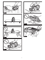
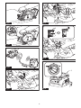
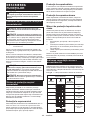
►Fig.7: 1. Red indicator 2. Button 3.Batterycartridge
Toremovethebatterycartridge,slideitfromthetool
while sliding the button on the front of the cartridge.
Toinstallthebatterycartridge,alignthetongueonthe
batterycartridgewiththegrooveinthehousingandslip
itintoplace.Insertitallthewayuntil itlocksinplace
withalittleclick.Ifyoucanseetheredindicatoras
showninthegure,itisnotlockedcompletely.
CAUTION: Always install the battery cartridge
fully until the red indicator cannot be seen. If not,
itmayaccidentallyfalloutofthetool,causinginjuryto
youorsomeonearoundyou.
CAUTION: Do not install the battery cartridge
forcibly.Ifthecartridgedoesnotslideineasily,itis
notbeinginsertedcorrectly.
Tool / battery protection system
Thetoolisequippedwithatool/batteryprotectionsys-
tem.Thissystemautomaticallycutsopowertothe
motortoextendtoolandbatterylife.Thetoolwillauto-
maticallystopduringoperationifthetoolorbatteryis
placed under one of the following conditions.
Overload protection
Whenthetool/batteryisoperatedinamannerthat
causesittodrawanabnormallyhighcurrent,thetool
automaticallystops.Inthissituation,turnthetoolo
and stop the application that caused the tool to become
overloaded. Then turn the tool on to restart.
Overheat protection
Whenthetoolorbatteryisoverheated,thetoolstops
automaticallyandthelampblinks.Inthiscase,letthe
toolandbatterycoolbeforeturningthetoolonagain.
Overdischarge protection
Whenthebatterycapacitybecomeslow,thetoolstops
automatically.Iftheproductdoesnotoperateeven
when the switches are operated, remove the batteries
from the tool and charge the batteries.

14 ENGLISH
Protections against other causes
Protectionsystemisalsodesignedforothercausesthatcould
damagethetoolandallowsthetooltostopautomatically.
Take all the following steps to clear the causes, when the tool
hasbeenbroughttoatemporaryhaltorstopinoperation.
1.
Turnthetoolo,andthenturnitonagaintorestart.
2. Chargethebattery(ies)orreplaceit/themwith
rechargedbattery(ies).
3. Letthetoolandbattery(ies)cooldown.
Ifnoimprovementcanbefoundbyrestoringprotection
system,thencontactyourlocalMakitaServiceCenter.
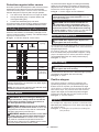
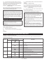
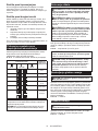
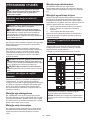
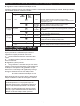
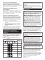
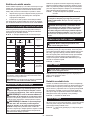
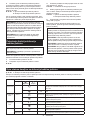
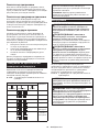
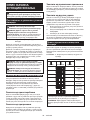
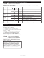
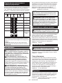
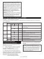
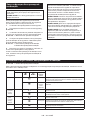
Indicating the remaining battery capacity
Pressthecheckbuttononthebatterycartridgetoindi-
catetheremainingbatterycapacity.Theindicatorlamps
light up for a few seconds.
►Fig.8: 1. Indicator lamps 2. Check button
Indicator lamps Remaining
capacity
Lighted O Blinking
75% to 100%
50% to 75%
25% to 50%
0% to 25%
Charge the
battery.
Thebattery
mayhave
malfunctioned.
NOTE: Depending on the conditions of use and the
ambienttemperature,theindicationmaydierslightly
fromtheactualcapacity.
NOTE:Therst(farleft)indicatorlampwillblinkwhen
thebatteryprotectionsystemworks.
Switch action
WARNING: Before installing the battery car-
tridge into the tool, always check to see that the
switch trigger actuates properly and returns to
the "OFF" position when released.
WARNING: NEVER defeat the lock-o button
by taping down or some other means. A switch with
anegatedlock-obuttonmayresultinunintentional
operationandseriouspersonalinjury.
WARNING: NEVER use the tool if it runs when
you simply pull the switch trigger without press-
ing the lock-o button. A switch in need of repair
mayresultinunintentionaloperationandserious
personalinjury.ReturntooltoaMakitaservicecenter
for proper repairs BEFORE further usage.
Topreventtheswitchtriggerfrombeingaccidentally
pulled,alock-obuttonisprovided.Tostartthetool,
depressthelock-obuttonandpulltheswitchtrigger.
Release the switch trigger to stop.
►Fig.9: 1. Switch trigger 2.Lock-obutton
NOTICE: Do not pull the switch trigger hard
without pressing in the lock-o button. This can
cause switch breakage.
CAUTION: The tool starts to brake the cir-
cular saw blade rotation immediately after you
release the switch trigger. Hold the tool rmly to
respond the reaction of the brake when releasing
the switch trigger. Sudden reaction can drop the tool
oyourhandandcancauseapersonalinjury.
Adjusting depth of cut
CAUTION: After adjusting the depth of cut,
always tighten the lever securely.
Loosen the lever on the depth guide and move the base
up or down. At the desired depth of cut, secure the base
bytighteningthelever.
For cleaner, safer cuts, set cut depth so that no more
thanonebladetoothprojectsbelowworkpiece.Using
proper cut depth helps to reduce potential for danger-
ousKICKBACKSwhichcancausepersonalinjury.
►Fig.10: 1. Lever
Bevel cutting
CAUTION: After adjusting the bevel angle,
always tighten the lever securely.
Loosentheleverandsetforthedesiredanglebytilting
accordingly,thentightentheleversecurely.
►Fig.11: 1. Lever
Positive stopper
The positive stopper is useful for setting the des-
ignatedanglequickly.Turnthepositivestopperso
thatthearrowonitpointsyourdesiredbevelangle
(22.5°/45°/50°). Loosen the lever and then tilt the tool
base until it stops. The position where the tool base
stopsistheangleyousetwiththepositivestopper.
Tighten the lever with the tool base at this position.
►Fig.12: 1. Positive stopper
Sighting
For straight cuts, align the 0° position on the front of the
basewithyourcuttingline.For45°bevelcuts,alignthe
45° position with it.
►Fig.13: 1. Cutting line (0° position) 2. Cutting line
(45° position)

15 ENGLISH
Lighting the lamp
CAUTION: Do not look in the light or see the
source of light directly.
To turn on the lamp without running the tool, pull the
switchtriggerwithoutpressingthelock-obutton.
To turn on the lamp with the tool running, press and hold
thelock-obuttonandpulltheswitchtrigger.
The lamp goes out 10 seconds after releasing the
switch trigger.
►Fig.14: 1. Lamp
NOTE:Useadryclothtowipethedirtothelensof
the lamp. Be careful not to scratch the lens of lamp, or
itmaylowertheillumination.
NOTE:Whenthetoolisoverheated,thelampblinks
for one minute. In this case, cool down the tool before
another operation.
Hook
CAUTION: Always remove the battery when
hanging the tool with the hook.
CAUTION: Never hook the tool at high loca-
tions or on the surfaces where the tool may lose
the balance and fall.Otherwisefallingaccidentmay
occurandcauseseriousinjury.
CAUTION: Do not pull the tool downward
when it is hooked.
Thehookisconvenientforhangingthetooltemporarily.
Tousethehook,simplyturnituntilitsnapsintothe
open position.
►Fig.15
Whennotinuse,alwaysturnthehookuntilitsnapsinto
the closed position.
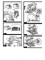
►Fig.16: 1. Hook 2. Open position 3. Closed position
Electric brake
This tool is equipped with an electric blade brake. If the
toolconsistentlyfailstoquicklystopthecircularsaw
blade after switch lever release, have tool serviced at a
Makita service center.
CAUTION: The blade brake system is not a
substitute for blade guard. NEVER USE TOOL
WITHOUT A FUNCTIONING BLADE GUARD.
SERIOUS PERSONAL INJURY CAN RESULT.
Electronic function
Thetoolsequippedwithelectronicfunctionareeasyto
operate because of the following feature(s).
Soft start feature
Soft start because of suppressed starting shock.
Constant speed control
Electronic speed control for obtaining constant speed.
Possibletogetnenish,becausetherotatingspeedis
kept constant even under load condition.
ASSEMBLY
CAUTION: Always be sure that the tool is
switched o and the battery cartridge is removed
before carrying out any work on the tool.
Hex wrench storage
Whennotinuse,storethehexwrenchasshowninthe
guretokeepitfrombeinglost.
►Fig.17: 1. Hex wrench
Installing and removing circular saw
blade
CAUTION: Be sure the circular saw blade is
installed with teeth pointing up at the front of the
tool.
CAUTION: Use only the Makita wrench to
install or remove the circular saw blade.
Installing circular saw blade
Thecircularsawblademayhavealreadybeeninstalled
at the time of shipment.
1. Loosen the lever on the depth guide and move the
base down.
2. Presstheshaftlockfullysothatthemounting
shaft cannot revolve and use the hex wrench to loosen
thehexbolt.Thenremovethehexboltandouterange.
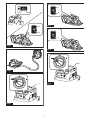
►Fig.18: 1. Shaft lock 2. Hex wrench 3. Loosen
4. Tighten
3. Installtheinnerange,ring(countryspecic),cir-
cularsawblade,outerangeandhexbolt.Atthistime,
align the direction of the arrow on the circular saw blade
with the arrow on the tool.
For tool without the ring
►Fig.19: 1. Hex bolt 2.Outerange3. Circular saw
blade 4. Arrow on the circular saw blade
5.Innerange6. Arrow on the tool
For tool with the ring
►Fig.20: 1. Hex bolt 2.Outerange3. Circular saw
blade 4. Arrow on the circular saw blade
5. Ring 6.Innerange7. Arrow on the tool
4. Press the shaft lock and tighten the hex bolt.
For tool with the inner ange for
other than 15.88 mm hole-diameter
saw blade
Theinnerangehasacertaindiameterprotrusionon
onesideofitandadierentdiameterprotrusiononthe
other side. Choose a correct side on which protrusion
tsintothesawbladeholeperfectly.Mounttheinner
angeontothemountingshaftsothatthecorrectside
ofprotrusionontheinnerangefacesoutwardandthen
placesawbladeandouterange.
►Fig.21: 1. Mounting shaft 2.Innerange3. Circular
saw blade 4.Outerange5. Hex bolt

16 ENGLISH
WARNING: BE SURE TO TIGHTEN THE HEX
BOLT SECURELY. Also be careful not to tighten
the bolt forcibly. Slipping your hand from the hex
wrench can cause a personal injury.
WARNING: Make sure that the protrusion "a"
on the inner ange that is positioned outside ts
into the saw blade hole "a" perfectly. Mounting the
blade on the wrong side can result in the dangerous
vibration.
For tool with the inner ange for a
15.88 mm hole-diameter saw blade
(country specic)
Mounttheinnerangewithitsrecessedsidefacing
outward onto the mounting shaft and then place circu-
lar saw blade (with the ring attached if needed), outer
angeandhexbolt.
For tool without the ring
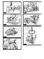
►Fig.22: 1. Mounting shaft 2.Innerange3. Circular
saw blade 4.Outerange5. Hex bolt
For tool with the ring
►Fig.23: 1. Mounting shaft 2.Innerange3. Circular
saw blade 4.Outerange5. Hex bolt
6. Ring
WARNING: BE SURE TO TIGHTEN THE HEX
BOLT SECURELY. Also be careful not to tighten
the bolt forcibly. Slipping your hand from the hex
wrench can cause a personal injury.
WARNING: If the ring is needed to mount the
blade onto the spindle, always be sure that the
correct ring for the blade's arbor hole you intend
to use is installed between the inner and the outer
anges.Useoftheincorrectarborholeringmay
result in the improper mounting of the blade causing
blade movement and severe vibration resulting in
possible loss of control during operation and in seri-
ouspersonalinjury.
Removing circular saw blade
1. Loosen the lever on the depth guide and move the
base down.
2. Presstheshaftlockfullysothatthemounting
shaft cannot revolve and use the hex wrench to loosen
thehexbolt.Thenremovethehexbolt,outerange,
circularsawbladeandring(countryspecic).
3. Installouterangeandhexboltagain.Pressthe
shaft lock and tighten the hex bolt.
Blade guard cleaning
Whenchangingthecircularsawblade,makesureto
also clean the upper and lower blade guards of accu-
mulated sawdust as discussed in the Maintenance
section.Sucheortsdonotreplacetheneedtocheck
lower guard operation before each use.
Connecting a vacuum cleaner
Whenyouwishtoperformcleancuttingoperation,
connectaMakitavacuumcleanertoyourtool.
Installthedustnozzleonthetoolusingthescrew.
►Fig.24: 1.Dustnozzle2. Screw
Connectahoseofthevacuumcleanertothedustnoz-
zleusingthefrontcu24(optionalaccessory).
►Fig.25: 1.Dustnozzle2.Frontcu243. Hose of
the vacuum cleaner
OPERATION
Thistoolisintendedtocutwoodproducts.Withappro-
priate Makita genuine circular saw blades, following
materials can also be sawed:
• Aluminum products
RefertoourwebsiteorcontactyourlocalMakitadealer
for the correct circular saw blades to be used for the
material to be cut.
Checking blade guard function
Removethebatterycartridge.
Set the bevel angle to 0°, and then retract the lower
guardmanuallytotheendandreleaseit.Thelower
guardisproperlyfunctioningif;
— itisretractedabovethebasewithoutanyhin-
drance and;
— itautomaticallyreturnsandcontactswiththe
stopper.
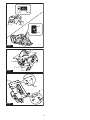
►Fig.26: 1. Upper guard 2. Lower guard 3. Base
4. Stopper 5. Open 6. Close
Ifthelowerguardisnotfunctioningproperly,checkif
saw dust is accumulated inside of the upper and lower
guards.Ifthelowerguardisnotfunctioningproperly
evenafterremovingdust,haveyourtoolservicedata
Makita service center.
Cutting operation
CAUTION: Wear dust mask when performing
cutting operation.
CAUTION: Be sure to move the tool forward
in a straight line gently. Forcing or twisting the tool
will result in overheating the motor and dangerous
kickback,possiblycausingsevereinjury.
NOTE:Whenthebatterycartridgetemperatureis
low,thetoolmaynotworktoitsfullcapacity.Atthis
time,forexample,usethetoolforalight-dutycutfor
awhileuntilthebatterycartridgewarmsupashigh
as room temperature. Then, the tool can work to its
fullcapacity.

17 ENGLISH
►Fig.27
Holdthetoolrmly.Thetoolisprovidedwithbothafront
grip and rear handle. Use both to best grasp the tool.
Ifbothhandsareholdingsaw,theycannotbecutby
the circular saw blade. Set the base on the workpiece
tobecutwithoutthecircularsawblademakingany
contact. Then turn the tool on and wait until the circular
sawbladeattainsfullspeed.Nowsimplymovethetool
forwardovertheworkpiecesurface,keepingitatand
advancingsmoothlyuntilthesawingiscompleted.
Togetcleancuts,keepyoursawinglinestraightand
yourspeedofadvanceuniform.Ifthecutfailstoprop-
erlyfollowyourintendedcutline,donotattempttoturn
orforcethetoolbacktothecutline.Doingsomaybind
the circular saw blade and lead to dangerous kickback
andpossibleseriousinjury.Releaseswitch,waitforcir-
cular saw blade to stop and then withdraw tool. Realign
tool on new cut line, and start cut again. Attempt to
avoid positioning which exposes operator to chips and
wooddustbeingejectedfromsaw.Useeyeprotection
tohelpavoidinjury.
Rip fence (Guide rule)
Optional accessory
CAUTION: Make sure that the rip fence is
securely installed in the correct position before
use.Improperattachmentmaycausedangerous
kickback.
►Fig.28: 1. Rip fence (Guide rule) 2. Clamping screw
Thehandyripfenceallowsyoutodoextra-accurate
straightcuts.Simplyslidetheripfenceupsnugly
against the side of the workpiece and secure it in posi-
tion with the clamping screw on the front of the base. It
also makes repeated cuts of uniform width possible.
WIRELESS ACTIVATION
FUNCTION
What you can do with the wireless
activation function
The wireless activation function enables clean and com-
fortableoperation.Byconnectingasupportedvacuum
cleanertothetool,youcanrunthevacuumcleaner
automaticallyalongwiththeswitchoperationofthetool.
►Fig.29
To use the wireless activation function, prepare follow-
ing items:
• Awirelessunit(optionalaccessory)
• A vacuum cleaner which supports the wireless
activation function
The overview of the wireless activation function
setting is as follows. Refer to each section for detail
procedures.
1. Installing the wireless unit
2. Tool registration for the vacuum cleaner
3. Starting the wireless activation function
Installing the wireless unit
Optional accessory
CAUTION: Place the tool on a at and stable
surface when installing the wireless unit.
NOTICE: Clean the dust and dirt on the tool
before installing the wireless unit. Dust or dirt
maycausemalfunctionifitcomesintotheslotofthe
wireless unit.
NOTICE: To prevent the malfunction caused by
static, touch a static discharging material, such
as a metal part of the tool, before picking up the
wireless unit.
NOTICE: When installing the wireless unit,
always be sure that the wireless unit is inserted
in the correct direction and the lid is completely
closed.
1. Openthelidonthetoolasshowninthegure.
►Fig.30: 1. Lid
2. Insert the wireless unit to the slot and then close
the lid.
Wheninsertingthewirelessunit,aligntheprojections
with the recessed portions on the slot.
►Fig.31: 1.Wirelessunit2.Projection3. Lid
4. Recessed portion
Whenremovingthewirelessunit,openthelidslowly.
The hooks on the back of the lid will lift the wireless unit
asyoupullupthelid.
►Fig.32: 1.Wirelessunit2. Hook 3. Lid
After removing the wireless unit, keep it in the supplied
case or a static-free container.
NOTICE: Always use the hooks on the back of
the lid when removing the wireless unit. If the
hooks do not catch the wireless unit, close the lid
completelyandopenitslowlyagain.
Tool registration for the vacuum
cleaner
NOTE: A Makita vacuum cleaner supporting the
wireless activation function is required for the tool
registration.
NOTE: Finish installing the wireless unit to the tool
before starting the tool registration.
NOTE: During the tool registration, do not pull the
switch trigger or turn on the power switch on the
vacuum cleaner.
NOTE: Refer to the instruction manual of the vacuum
cleaner, too.
Ifyouwishtoactivatethevacuumcleaneralongwith
theswitchoperationofthetool,nishthetoolregistra-
tion beforehand.
1. Install the batteries to the vacuum cleaner and the
tool.
2. Setthestand-byswitchonthevacuumcleanerto
"AUTO".
►Fig.33: 1.Stand-byswitch

18 ENGLISH
3. Press the wireless activation button on the vac-
uum cleaner for 3 seconds until the wireless activation
lamp blinks in green. And then press the wireless acti-
vationbuttononthetoolinthesameway.
►Fig.34: 1.Wirelessactivationbutton2.Wireless
activation lamp
If the vacuum cleaner and the tool are linked success-
fully,thewirelessactivationlampswilllightupingreen
for 2 seconds and start blinking in blue.
NOTE:Thewirelessactivationlampsnishblinking
in green after 20 seconds elapsed. Press the wireless
activation button on the tool while the wireless acti-
vation lamp on the cleaner is blinking. If the wireless
activation lamp does not blink in green, push the wire-
lessactivationbuttonbrieyandholditdownagain.
NOTE:Whenperformingtwoormoretoolregistra-
tionsforonevacuumcleaner,nishthetoolregistra-
tiononebyone.
Starting the wireless activation function
NOTE: Finish the tool registration for the vacuum
cleaner prior to the wireless activation.
NOTE: Refer to the instruction manual of the vacuum
cleaner, too.
After registering a tool to the vacuum cleaner, the
vacuumcleanerwillautomaticallyrunsalongwiththe
switch operation of the tool.
1. Install the wireless unit to the tool.
2. Connect the hose of the vacuum cleaner with the
tool.
►Fig.35
3. Setthestand-byswitchonthevacuumcleanerto
"AUTO".
►Fig.36: 1.Stand-byswitch
4. Push the wireless activation button on the tool
briey.Thewirelessactivationlampwillblinkinblue.
►Fig.37: 1.Wirelessactivationbutton2.Wireless
activation lamp
5. Turn on the tool. Check if the vacuum cleaner runs
while the tool is operating.
To stop the wireless activation of the vacuum cleaner,
push the wireless activation button on the tool.
NOTE: The wireless activation lamp on the tool will
stop blinking in blue when there is no operation for
2hours.Inthiscase,setthestand-byswitchonthe
vacuum cleaner to "AUTO" and push the wireless
activation button on the tool again.
NOTE:Thevacuumcleanerstarts/stopswithadelay.
There is a time lag when the vacuum cleaner detects
a switch operation of the tool.
NOTE: The transmission distance of the wireless unit
mayvarydependingonthelocationandsurrounding
circumstances.
NOTE:Whentwoormoretoolsareregisteredto
onevacuumcleaner,thevacuumcleanermaystart
runningevenifyoudonotturnonyourtoolbecause
another user is using the wireless activation function.
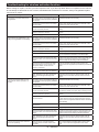
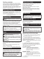
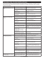
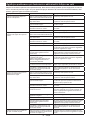
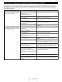
Description of the wireless activation lamp status
►Fig.38: 1.Wirelessactivationlamp
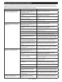
The wireless activation lamp shows the status of the wireless activation function. Refer to the table below for the
meaning of the lamp status.
Status Wireless activation lamp Description
Color
On
Blinking
Duration
Standby Blue 2 hours The wireless activation of the vacuum cleaner is available. The
lampwillautomaticallyturnowhennooperationisperformed
for 2 hours.
When
the tool is
running.
The wireless activation of the vacuum cleaner is available and the
tool is running.
Tool
registration Green 20 seconds Readyforthetoolregistration.Waitingfortheregistrationbythe
vacuum cleaner.
2 seconds Thetoolregistrationhasbeennished.Thewirelessactivation
lamp will start blinking in blue.
Cancelling
tool
registration
Red 20 seconds Readyforthecancellationofthetoolregistration.Waitingforthe
cancellationbythevacuumcleaner.
2 seconds Thecancellationofthetoolregistrationhasbeennished.The
wireless activation lamp will start blinking in blue.
Others Red 3 seconds The power is supplied to the wireless unit and the wireless activa-
tion function is starting up.
O - - The wireless activation of the vacuum cleaner is stopped.

19 ENGLISH
Cancelling tool registration for the
vacuum cleaner
Perform the following procedure when cancelling the
tool registration for the vacuum cleaner.
1. Install the batteries to the vacuum cleaner and the
tool.
2. Setthestand-byswitchonthevacuumcleanerto
"AUTO".
►Fig.39: 1.Stand-byswitch
3. Press the wireless activation button on the vac-
uum cleaner for 6 seconds. The wireless activation
lamp blinks in green and then become red. After that,
press the wireless activation button on the tool in the
sameway.
►Fig.40: 1.Wirelessactivationbutton2.Wireless
activation lamp
Ifthecancellationisperformedsuccessfully,thewire-
less activation lamps will light up in red for 2 seconds
and start blinking in blue.
NOTE:Thewirelessactivationlampsnishblinkingin
red after 20 seconds elapsed. Press the wireless acti-
vation button on the tool while the wireless activation
lamp on the cleaner is blinking. If the wireless acti-
vation lamp does not blink in red, push the wireless
activationbuttonbrieyandholditdownagain.

20 ENGLISH
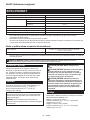
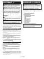
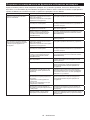
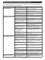
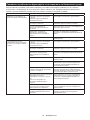
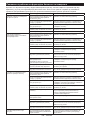
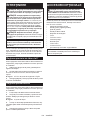
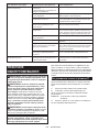
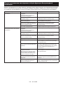
Troubleshooting for wireless activation function
Beforeaskingforrepairs,conductyourowninspectionrst.Ifyoundaproblemthatisnotexplainedinthemanual,
donotattempttodismantlethetool.Instead,askMakitaAuthorizedServiceCenters,alwaysusingMakitareplace-
ment parts for repairs.
State of abnormality Probable cause (malfunction) Remedy
The wireless activation lamp does
not light/blink.
The wireless unit is not installed into the tool.
Thewirelessunitisimproperlyinstalled
into the tool.
Installthewirelessunitcorrectly.
The terminal of the wireless unit and/or
theslotisdirty.
Gentlywipeodustanddirtontheterminalofthe
wireless unit and clean the slot.
The wireless activation button on the
tool has not been pushed. Push the wireless activation button on the tool
briey.
Thestand-byswitchonthevacuum
cleaner is not set to "AUTO". Setthestand-byswitchonthevacuumcleanerto
"AUTO".
Nopowersupply
Supplythepowertothetoolandthevacuumcleaner.
Cannotnishtoolregistration/can-
cellingtoolregistrationsuccessfully.
The wireless unit is not installed into the tool.
Thewirelessunitisimproperlyinstalled
into the tool.
Installthewirelessunitcorrectly.
The terminal of the wireless unit and/or
theslotisdirty.
Gentlywipeodustanddirtontheterminalofthe
wireless unit and clean the slot.
Thestand-byswitchonthevacuum
cleaner is not set to "AUTO". Setthestand-byswitchonthevacuumcleanerto
"AUTO".
Nopowersupply
Supplythepowertothetoolandthevacuumcleaner.
Incorrect operation
Pushthewirelessactivationbuttonbrieyandperform
the tool registration/cancellation procedures again.
Thetoolandvacuumcleanerareaway
from each other (out of the transmission
range).
Get the tool and vacuum cleaner closer to each other. The
maximumtransmissiondistanceisapproximately10m
howeveritmayvaryaccordingtothecircumstances.
Beforenishingthetoolregistration/cancellation;
- the switch of the tool is turned on or;
- the power button on the vacuum
cleaner is turned on.
Pushthewirelessactivationbuttonbrieyand
perform the tool registration/cancellation procedures
again.
The tool registration procedures for the
toolorvacuumcleanerhavenotnished.
Perform the tool registration procedures for both the
tool and the vacuum cleaner at the same timing.
Radiodisturbancebyotherappliances
whichgeneratehigh-intensityradio
waves.
Keepthetoolandvacuumcleanerawayfromthe
appliancessuchasWi-Fidevicesandmicrowave
ovens.
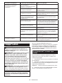
The vacuum cleaner does not run
along with the switch operation of
the tool.
The wireless unit is not installed into the tool.
Thewirelessunitisimproperlyinstalled
into the tool.
Installthewirelessunitcorrectly.
The terminal of the wireless unit and/or
theslotisdirty.
Gentlywipeodustanddirtontheterminalofthe
wireless unit and clean the slot.
The wireless activation button on the
tool has not been pushed.
Pushthewirelessactivationbuttonbrieyandmake
sure that the wireless activation lamp is blinking in blue.
Thestand-byswitchonthevacuum
cleaner is not set to "AUTO". Setthestand-byswitchonthevacuumcleanerto
"AUTO".
More than 10 tools are registered to the
vacuum cleaner. Perform the tool registration again.
If more than 10 tools are registered to the vacuum
cleaner, the tool registered earliest will be cancelled
automatically.
The vacuum cleaner erased all tool
registrations. Perform the tool registration again.
Nopowersupply
Supplythepowertothetoolandthevacuumcleaner.
Thetoolandvacuumcleanerareaway
from each other (out of the transmission
range).
Get the tool and vacuum cleaner closer each other. The
maximumtransmissiondistanceisapproximately10m
howeveritmayvaryaccordingtothecircumstances.
Radiodisturbancebyotherappliances
whichgeneratehigh-intensityradio
waves.
Keepthetoolandvacuumcleanerawayfromthe
appliancessuchasWi-Fidevicesandmicrowave
ovens.
The vacuum cleaner runs while the
tool is not operating. Other users are using the wireless
activation of the vacuum cleaner with
their tools.
Turnothewirelessactivationbuttonoftheother
tools or cancel the tool registration of the other
tools.
Pagina se încarcă ...
Pagina se încarcă ...
Pagina se încarcă ...
Pagina se încarcă ...
Pagina se încarcă ...
Pagina se încarcă ...
Pagina se încarcă ...
Pagina se încarcă ...
Pagina se încarcă ...
Pagina se încarcă ...
Pagina se încarcă ...
Pagina se încarcă ...
Pagina se încarcă ...
Pagina se încarcă ...
Pagina se încarcă ...
Pagina se încarcă ...
Pagina se încarcă ...
Pagina se încarcă ...
Pagina se încarcă ...
Pagina se încarcă ...
Pagina se încarcă ...
Pagina se încarcă ...
Pagina se încarcă ...
Pagina se încarcă ...
Pagina se încarcă ...
Pagina se încarcă ...
Pagina se încarcă ...
Pagina se încarcă ...
Pagina se încarcă ...
Pagina se încarcă ...
Pagina se încarcă ...
Pagina se încarcă ...
Pagina se încarcă ...
Pagina se încarcă ...
Pagina se încarcă ...
Pagina se încarcă ...
Pagina se încarcă ...
Pagina se încarcă ...
Pagina se încarcă ...
Pagina se încarcă ...
Pagina se încarcă ...
Pagina se încarcă ...
Pagina se încarcă ...
Pagina se încarcă ...
Pagina se încarcă ...
Pagina se încarcă ...
Pagina se încarcă ...
Pagina se încarcă ...
Pagina se încarcă ...
Pagina se încarcă ...
Pagina se încarcă ...
Pagina se încarcă ...
Pagina se încarcă ...
Pagina se încarcă ...
Pagina se încarcă ...
Pagina se încarcă ...
Pagina se încarcă ...
Pagina se încarcă ...
Pagina se încarcă ...
Pagina se încarcă ...
Pagina se încarcă ...
Pagina se încarcă ...
Pagina se încarcă ...
Pagina se încarcă ...
Pagina se încarcă ...
Pagina se încarcă ...
Pagina se încarcă ...
Pagina se încarcă ...
Pagina se încarcă ...
Pagina se încarcă ...
Pagina se încarcă ...
Pagina se încarcă ...
Pagina se încarcă ...
Pagina se încarcă ...
Pagina se încarcă ...
Pagina se încarcă ...
Pagina se încarcă ...
Pagina se încarcă ...
Pagina se încarcă ...
Pagina se încarcă ...
Pagina se încarcă ...
Pagina se încarcă ...
Pagina se încarcă ...
Pagina se încarcă ...
Pagina se încarcă ...
Pagina se încarcă ...
Pagina se încarcă ...
Pagina se încarcă ...
Pagina se încarcă ...
Pagina se încarcă ...
Pagina se încarcă ...
Pagina se încarcă ...
Pagina se încarcă ...
Pagina se încarcă ...
Pagina se încarcă ...
Pagina se încarcă ...
Pagina se încarcă ...
Pagina se încarcă ...
Pagina se încarcă ...
Pagina se încarcă ...
Pagina se încarcă ...
Pagina se încarcă ...
Pagina se încarcă ...
Pagina se încarcă ...
Pagina se încarcă ...
Pagina se încarcă ...
Pagina se încarcă ...
Pagina se încarcă ...
Pagina se încarcă ...
Pagina se încarcă ...
Pagina se încarcă ...
Pagina se încarcă ...
Pagina se încarcă ...
Pagina se încarcă ...
Pagina se încarcă ...
Pagina se încarcă ...
Pagina se încarcă ...
Pagina se încarcă ...
Pagina se încarcă ...
Pagina se încarcă ...
Pagina se încarcă ...
Pagina se încarcă ...
Pagina se încarcă ...
Pagina se încarcă ...
Pagina se încarcă ...
Pagina se încarcă ...
Pagina se încarcă ...
Pagina se încarcă ...
Pagina se încarcă ...
Pagina se încarcă ...
Pagina se încarcă ...
Pagina se încarcă ...
-
 1
1
-
 2
2
-
 3
3
-
 4
4
-
 5
5
-
 6
6
-
 7
7
-
 8
8
-
 9
9
-
 10
10
-
 11
11
-
 12
12
-
 13
13
-
 14
14
-
 15
15
-
 16
16
-
 17
17
-
 18
18
-
 19
19
-
 20
20
-
 21
21
-
 22
22
-
 23
23
-
 24
24
-
 25
25
-
 26
26
-
 27
27
-
 28
28
-
 29
29
-
 30
30
-
 31
31
-
 32
32
-
 33
33
-
 34
34
-
 35
35
-
 36
36
-
 37
37
-
 38
38
-
 39
39
-
 40
40
-
 41
41
-
 42
42
-
 43
43
-
 44
44
-
 45
45
-
 46
46
-
 47
47
-
 48
48
-
 49
49
-
 50
50
-
 51
51
-
 52
52
-
 53
53
-
 54
54
-
 55
55
-
 56
56
-
 57
57
-
 58
58
-
 59
59
-
 60
60
-
 61
61
-
 62
62
-
 63
63
-
 64
64
-
 65
65
-
 66
66
-
 67
67
-
 68
68
-
 69
69
-
 70
70
-
 71
71
-
 72
72
-
 73
73
-
 74
74
-
 75
75
-
 76
76
-
 77
77
-
 78
78
-
 79
79
-
 80
80
-
 81
81
-
 82
82
-
 83
83
-
 84
84
-
 85
85
-
 86
86
-
 87
87
-
 88
88
-
 89
89
-
 90
90
-
 91
91
-
 92
92
-
 93
93
-
 94
94
-
 95
95
-
 96
96
-
 97
97
-
 98
98
-
 99
99
-
 100
100
-
 101
101
-
 102
102
-
 103
103
-
 104
104
-
 105
105
-
 106
106
-
 107
107
-
 108
108
-
 109
109
-
 110
110
-
 111
111
-
 112
112
-
 113
113
-
 114
114
-
 115
115
-
 116
116
-
 117
117
-
 118
118
-
 119
119
-
 120
120
-
 121
121
-
 122
122
-
 123
123
-
 124
124
-
 125
125
-
 126
126
-
 127
127
-
 128
128
-
 129
129
-
 130
130
-
 131
131
-
 132
132
-
 133
133
-
 134
134
-
 135
135
-
 136
136
-
 137
137
-
 138
138
-
 139
139
-
 140
140
-
 141
141
-
 142
142
-
 143
143
-
 144
144
-
 145
145
-
 146
146
-
 147
147
-
 148
148
-
 149
149
-
 150
150
-
 151
151
-
 152
152


Makita HS012G Cordless Circular Saw Manual de utilizare
- Tip
- Manual de utilizare
Lucrări conexe
-
Makita DHS680 Manual de utilizare
-
Makita HS003G Manual de utilizare
-
Makita DHS782 Manual de utilizare
-
Makita CS002G Manual de utilizare
-
-
Makita DLS714 Manual de utilizare
-
-
Makita HS6101 Manual de utilizare
-
Makita MT582 Manual de utilizare
-
Makita 5704R Manual de utilizare