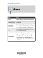
Ubiquiti US-16-150W Ghid de inițiere rapidă
- Categorie
- Comutatoare de rețea
- Tip
- Ghid de inițiere rapidă

Managed PoE+ Gigabit Switch
with SFP
Model: US-16-150W

Introduction
Thank you for purchasing the Ubiquiti Networks® UniFi®
Switch. This Quick Start Guide is designed to guide you
through the installation and also includes the warranty terms.
Package Contents
UniFi Switch US-16-150W
Power Cord Rack-Mount Brackets
(Qty. 2)
Bracket Screws
(M4, Qty. 8)
Managed PoE+ Gigabit Switch
with SFP
Model: US-16-150
Mounting Screws
(#10-32 x 5/8", Qty. 4)
Cage Nuts
(#10-32 x 5/8", Qty. 4)
Quick Start
Guide
TERMS OF USE: All Ethernet cabling runs must use CAT5 (or above). It is the customer’s
responsibility to follow local country regulations, including operation within legal frequency
channels, output power, indoor cabling requirements, and Dynamic Frequency Selection
(DFS) requirements.

System Requirements
• Linux, MacOSX, or Microsoft Windows 7/8/10
• Java Runtime Environment 1.6 (1.8 or newer recommended)
• Web Browser: Mozilla Firefox, Google Chrome, Microsoft
Edge, or Microsoft Internet Explorer 10 (or newer)
• UniFi Controller software v4.8.5 or newer (available at:
downloads.ubnt.com/unifi)
Installation Requirements
• Phillips screwdriver (for rack-mounting)
• Standard-sized, 19" wide rack with a minimum of 1U height
available (for rack-mounting)
• For indoor applications, use Category 5 (or above) UTP
cabling approved for indoor use.
• For outdoor applications, shielded Category 5 (or above)
cabling should be used for all wired Ethernet connections
and should be grounded through the AC ground of the
power supply.
We recommend that you protect your outdoor networks
from the most brutal environments and devastating ESD
attacks with industrial-grade shielded Ethernet cable,
TOUGHCable
™
, from Ubiquiti Networks. For more details,
visit: www.ubnt.com/toughcable
Note: Although the cabling can be located outdoors,
the UniFi Switch itself should be housed inside a
protective enclosure.

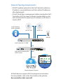
Network Topology Requirements
• A DHCP-enabled network for the UniFi Switch to obtain an
IPaddress (connected devices will also obtain IP addresses
after deployment)
• A UniFi Cloud Key or management station running the UniFi
Controller v4.8.5 (or newer) software, located either on-site
and connected to the same Layer2 network, or off-site in a
cloud or NOC
UniFi Switch US-16-150W
UniFi Security Gateway Pro
(DHCP Server)
Internet
UAP-AC-PRO UAP-AC-LR
UAP-IW
LAN
WAN
UniFi Cloud Key
(UniFi Controller)
Remote Access to
UniFi Controller
Network Health
DASHBOARD
MAP
DEVICES
CLIENTS
CALLS
STATISTICS
INSIGHTS
SETTINGS
CURRENT SITE
Default
REFRESH RATE
2 minutes
Sample Network Diagram
All UniFi devices support off-site management controllers.
For setup details, refer to the User Guide on the website:
documentation.ubnt.com/unifi

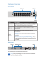
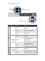
Hardware Overview
Front Panel
RJ45 1-16 SFP 1-2
Reset
Button
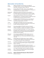
Port Description
RJ45 1-16
RJ45 ports support Power over Ethernet (PoE)
and 10/100/1000 Ethernet connections.
SFP 1-2
Hot-swappable SF P ports support 1 Gbps
connections.
Reset
Button
This button serves two functions for the
UniFi Switch:
• Restart Press and release the Reset button
quickly.
• Restore to Factory Default Settings Press
and hold the Reset button for more than five
seconds.
Back Panel
Power
Console Ventilation Fans
The Console port is reserved for future use.
Note: Keep a clearance of 20 mm from the ventilation
fans for adequate airflow.

Front Panel System LED
System
State Status
White Factory defaults, waiting for integration.
Flashing White Initializing.
Alternating
White/Blue
Device is busy; do not use or unplug it.
This usually indicates that a process such
as a firmware upgrade is taking place.
Blue
Successfully integrated into a network
and working properly.
Flashing Blue
This is used to locate a device.
When you click Locate in the UniFi
Controller software, the System LED
will flash blue. The software will also
display the location of the UniFi Switch
on the map.
*640-00172-01*
640-00172-01

Front Panel Port LEDs
SFP:
Speed/Link/Activity
RJ45:
PoE
RJ45:
Speed/Link/Activity
LED State Status
RJ45 1-16
PoE
Off No PoE
Amber IEEE 802.3af/802.3at
Green 24V Passive
Speed/
Link/
Activity
Off No Link
Amber
Link Established at
10/100Mbps
Flashing Indicates Activity
Green
Link Established at
1000Mbps (1 Gbps)
Flashing Indicates Activity
SFP 1-2
Speed/
Link/
Activity
Off No Link
Green
Link Established at 1Gbps
Flashing Indicates Activity

Hardware Installation
The UniFi Switch can be placed on a horizontal surface or
mounted in a rack.
Note: Keep a clearance of 20 mm next to the ventilation
holes for adequate airflow.
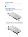
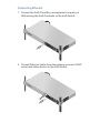
Mounting in a Rack (Optional)
1. Attach the Rack-Mount Brackets to the UniFi Switch using
the eight Bracket Screws.
2. Attach the UniFi Switch to the rack using the four Mounting
Screws. (If the rack has square slots, then use the Cage Nuts
with the Mounting Screws.)

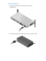
Connecting Power
1. Connect the Power Cord to the Power port of the
UniFiSwitch.
2. Connect the other end of the Power Cord to a power outlet.

Connecting Ethernet
1. Connect the UniFi Cloud Key, management computer, or
LAN running the UniFi Controller to the UniFi Switch.
2. Connect Ethernet cables from the gateway or router (DHCP
server) and other devices to the UniFi Switch.

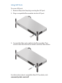
Using SFP Ports
To use an SFP port:
1. Remove the protective plug covering the SFP port.
2. Plug a compatible fiber module into the SFP port.
1000Mbps SM/SC 20KM DDM
Tx1550nm/Rx1310nm
3. Connect the fiber optic cable to the fiber module. Then
connect the other end of the cable to another fiber device.
For information about compatible fiber SFP modules, visit:
community.ubnt.com/unifi

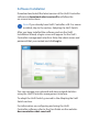
Software Installation
Download and install the latest version of the UniFi Controller
software at downloads.ubnt.com/unifi and follow the
on-screen instructions.
Note: If you already have UniFi Controller v4.8.5 or newer
installed, skip to the section, Adopting the UniFi Switch.
After you have installed the software and run the UniFi
Installation Wizard, a login screen will appear for the UniFi
Controller management interface. Enter the admin name and
password that you created and click Log In.
You can manage your network and view network statistics
using the UniFi Controller management interface.
To adopt the UniFi Switch, proceed to the Adopting the UniFi
Switch section.
For information on configuring and using the UniFi
Controller software, refer to the User Guide on the website:
documentation.ubnt.com/unifi

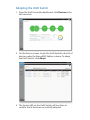
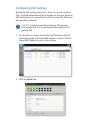
Adopting the UniFi Switch
1. From the UniFi Controller dashboard, click Devices in the
left menu bar.
2. On the Devices screen, locate the UniFi Switch in the list of
devices under the Name/MAC Address column. To adopt
the UniFi Switch, click Adopt.
3. The System LED on the UniFi Switch will turn blue to
confirm that it has been successfully adopted.

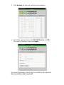
Configuring PoE Settings
By default, PoE settings for ports 1-8 are set to auto-sensing
PoE+. PoE will automatically be activated on the port when an
802.3af/at device is connected. For 24V passive PoE, PoE must
be manually activated.
WARNING: Before manually activating 24V passive
PoE, ensure that the connected device supports 24V
passive PoE.
1. On the Devices screen, locate the UniFi Switch in the list
of devices under the Name/MAC Address column. Click its
Name/MAC Address to access its settings.
2. Click the Ports tab.

3. Click Actions for the port you want to configure.
4. Select the appropriate mode: Off, 24V Passive, or PoE+
from the PoE setting. ThenclickApply.
For more information, refer to the User Guide on the website:
documentation.ubnt.com/unifi

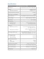
Specifications
UniFi Switch US-16-150W
Dimensions
443 x 43 x 221 mm (17.44 x 1.69 x 8.70")
Weight
With Mount Brackets
2.80 kg (6.17 lb)
2.89 kg (6.37 lb)
Total Non-Blocking Line Rate 18 Gbps
Max. Power Consumption 150W
Power Method 100-240VAC/50-60 Hz, Universal Input
Power Supply AC/DC, Internal, 150W DC
Rack-Mount Yes, 1U High
LEDs Per Port
RJ45 Data Ports
SFP Data Ports
PoE, Speed/Link/Activity
Speed/Link/Activity
Interfaces
Networking Interfaces
Management Interface
(16) 10/100/1000 Mbps RJ45 Ports
(2) 1 Gbps SFP Ports
UART Console Out-of-Band,
Ethernet In-Band
PoE Output (RJ45 Ports) PoE+ IEEE 802.3af/at (pins 1, 2+; 3, 6-)
24VDC Passive PoE (pins 4, 5+; 7, 8-)
PoE Voltage Range
802.3at Mode
24V Passive PoE
50-57V
20-27V
Max. Wattage per Port
PoE+
Passive PoE
34.2W
17W
Operating Temperature -5 to 40° C (23 to 104° F)
Operating Humidity 5 to 95% Noncondensing
Shock and Vibration ETSI300-019-1.4 Standard
Certications CE, FCC, IC

Safety Notices
1. Read, follow, and keep these instructions.
2. Heed all warnings.
3. Only use attachments/accessories specified by the manufacturer.
WARNING: Do not use this product in location that can
be submerged by water.
WARNING: Avoid using this product during an electrical
storm. There may be a remote risk of electric shock from
lightning.
Electrical Safety Information
1. Compliance is required with respect to voltage, frequency, and current
requirements indicated on the manufacturer’s label. Connection to a
different power source than those specified may result in improper
operation, damage to the equipment or pose a fire hazard if the
limitations are not followed.
2. There are no operator serviceable parts inside this equipment. Service
should be provided only by a qualified service technician.
3. This equipment is provided with a detachable power cord which has
an integral safety ground wire intended for connection to a grounded
safety outlet.
a. Do not substitute the power cord with one that is not the provided
approved type. Never use an adapter plug to connect to a 2-wire
outlet as this will defeat the continuity of the grounding wire.
b. The equipment requires the use of the ground wire as a part of the
safety certification, modification or misuse can provide a shock
hazard that can result in serious injury or death.
c. Contact a qualified electrician or the manufacturer if there
are questions about the installation prior to connecting the
equipment.
d. Protective earthing is provided by Listed AC adapter. Building
installation shall provide appropriate short-circuit backup
protection.
e. Protective bonding must be installed in accordance with local
national wiring rules and regulations.

Limited Warranty
UBIQUITI NETWORKS, Inc (“UBIQUITI NETWORKS”) warrants that the
product(s) furnished hereunder (the “Product(s)”) shall be free from defects
in material and workmanship for a period of one (1) year from the date
of shipment by UBIQUITI NETWORKS under normal use and operation.
UBIQUITI NETWORKS’ sole and exclusive obligation and liability under
the foregoing warranty shall be for UBIQUITI NETWORKS, at its discretion,
to repair or replace any Product that fails to conform to the above
warranty during the above warranty period. The expense of removal and
reinstallation of any Product is not included in this warranty. The warranty
period of any repaired or replaced Product shall not extend beyond its
original term.
Warranty Conditions
The above warranty does not apply if the Product:
(I) has been modified and/or altered, or an addition made thereto,
except by Ubiquiti Networks, or Ubiquiti Networks’ authorized
representatives, or as approved by Ubiquiti Networks in writing;
(II) has been painted, rebranded or physically modified in any way;
(III) has been damaged due to errors or defects in cabling;
(IV) has been subjected to misuse, abuse, negligence, abnormal physical,
electromagnetic or electrical stress, including lightning strikes, or
accident;
(V) has been damaged or impaired as a result of using third party
firmware;
(VI) has no original Ubiquiti MAC label, or is missing any other original
Ubiquiti label(s); or
(VII) has not been received by Ubiquiti within 30 days of issuance of
the RMA.
In addition, the above warranty shall apply only if: the product has been
properly installed and used at all times in accordance, and in all material
respects, with the applicable Product documentation; all Ethernet cabling
runs use CAT5 (or above), and for outdoor installations, shielded Ethernet
cabling is used, and for indoor installations, indoor cabling requirements
are followed.
Returns
No Products will be accepted for replacement or repair without obtaining
a Return Materials Authorization (RMA) number from UBIQUITI NETWORKS
during the warranty period, and the Products being received at UBIQUITI
NETWORKS’ facility freight prepaid in accordance with the RMA process of
UBIQUITI NETWORKS. Products returned without an RMA number will not
be processed and will be returned freight collect or subject to disposal.
Information on the RMA process and obtaining an RMA number can be
found at: www.ubnt.com/support/warranty.

Disclaimer
EXCEPT FOR ANY EXPRESS WARRANTIES PROVIDED HEREIN, UBIQUITI
NETWORKS, ITS AFFILIATES, AND ITS AND THEIR THIRD PARTY DATA,
SERVICE, SOFTWARE AND HARDWARE PROVIDERS HEREBY DISCLAIM
AND MAKE NO OTHER REPRESENTATION OR WARRANTY OF ANY KIND,
EXPRESS, IMPLIED OR STATUTORY, INCLUDING, BUT NOT LIMITED TO,
REPRESENTATIONS, GUARANTEES, OR WARRANTIES OF MERCHANTABILITY,
ACCURACY, QUALITY OF SERVICE OR RESULTS, AVAILABILITY,
SATISFACTORY QUALITY, LACK OF VIRUSES, QUIET ENJOYMENT, FITNESS
FOR A PARTICULAR PURPOSE AND NON-INFRINGEMENT AND ANY
WARRANTIES ARISING FROM ANY COURSE OF DEALING, USAGE OR
TRADE PRACTICE IN CONNECTION WITH SUCH PRODUCTS AND SERVICES.
BUYER ACKNOWLEDGES THAT NEITHER UBIQUITI NETWORKS NOR
ITS THIRD PARTY PROVIDERS CONTROL BUYER’S EQUIPMENT OR THE
TRANSFER OF DATA OVER COMMUNICATIONS FACILITIES, INCLUDING
THE INTERNET, AND THAT THE PRODUCTS AND SERVICES MAY BE
SUBJECT TO LIMITATIONS, INTERRUPTIONS, DELAYS, CANCELLATIONS
AND OTHER PROBLEMS INHERENT IN THE USE OF COMMUNICATIONS
FACILITIES. UBIQUITI NETWORKS, ITS AFFILIATES AND ITS AND THEIR THIRD
PARTY PROVIDERS ARE NOT RESPONSIBLE FOR ANY INTERRUPTIONS,
DELAYS, CANCELLATIONS, DELIVERY FAILURES, DATA LOSS, CONTENT
CORRUPTION, PACKET LOSS, OR OTHER DAMAGE RESULTING FROM ANY
OF THE FOREGOING. In addition, UBIQUITI NETWORKS does not warrant
that the operation of the Products will be error-free or that operation will
be uninterrupted. In no event shall UBIQUITI NETWORKS be responsible
for damages or claims of any nature or description relating to system
performance, including coverage, buyer’s selection of products (including
the Products) for buyer’s application and/or failure of products (including
the Products) to meet government or regulatory requirements.
Limitation of Liability
EXCEPT TO THE EXTENT PROHIBITED BY LOCAL LAW, IN NO EVENT WILL
UBIQUITI OR ITS SUBSIDIARIES, AFFILIATES OR SUPPLIERS BE LIABLE FOR
DIRECT, SPECIAL, INCIDENTAL, CONSEQUENTIAL OR OTHER DAMAGES
(INCLUDING LOST PROFIT, LOST DATA, OR DOWNTIME COSTS), ARISING
OUT OF THE USE, INABILITY TO USE, OR THE RESULTS OF USE OF THE
PRODUCT, WHETHER BASED IN WARRANTY, CONTRACT, TORT OR OTHER
LEGAL THEORY, AND WHETHER OR NOT ADVISED OF THE POSSIBILITY OF
SUCH DAMAGES.

Note
Some countries, states and provinces do not allow exclusions of implied
warranties or conditions, so the above exclusion may not apply to you.
You may have other rights that vary from country to country, state to
state, or province to province. Some countries, states and provinces do not
allow the exclusion or limitation of liability for incidental or consequential
damages, so the above limitation may not apply to you. EXCEPT TO
THE EXTENT ALLOWED BY LOCAL LAW, THESE WARRANTY TERMS DO
NOT EXCLUDE, RESTRICT OR MODIFY, AND ARE IN ADDITION TO, THE
MANDATORY STATUTORY RIGHTS APPLICABLE TO THE LICENSE OF ANY
SOFTWARE (EMBEDDED IN THE PRODUCT) TO YOU. The United Nations
Convention on Contracts for the International Sale of Goods shall not apply
to any transactions regarding the sale of the Products.
Compliance
FCC
Changes or modifications not expressly approved by the party responsible
for compliance could void the user’s authority to operate the equipment.
This device complies with Part 15 of the FCC Rules. Operation is subject to
the following two conditions:
1. This device may not cause harmful interference, and
2. This device must accept any interference received, including
interference that may cause undesired operation.
NOTE: This equipment has been tested and found to comply with the
limits for a Class A digital device, pursuant to part 15 of the FCC Rules.
These limits are designed to provide reasonable protection against
harmful interference when the equipment is operated in a commercial
environment. This equipment generates, uses, and can radiate radio
frequency energy and, if not installed and used in accordance with
the instruction manual, may cause harmful interference to radio
communications. Operations of this equipment in a residential area is likely
to cause harmful interference in which case the user will be required to
correct the interference at his own expense.
Industry Canada
CAN ICES-3(A)/NMB-3(A)
This Class A digital apparatus complies with Canadian CAN ICES-3(A).
CAN ICES-3(A)/NMB-3(A)
Cet appareil numérique de la classe A est conforme à la norme NMB-3(A)
Canada.
Pagina se încarcă...
Pagina se încarcă...
Pagina se încarcă...
Pagina se încarcă...
-
 1
1
-
 2
2
-
 3
3
-
 4
4
-
 5
5
-
 6
6
-
 7
7
-
 8
8
-
 9
9
-
 10
10
-
 11
11
-
 12
12
-
 13
13
-
 14
14
-
 15
15
-
 16
16
-
 17
17
-
 18
18
-
 19
19
-
 20
20
-
 21
21
-
 22
22
-
 23
23
-
 24
24


Ubiquiti US-16-150W Ghid de inițiere rapidă
- Categorie
- Comutatoare de rețea
- Tip
- Ghid de inițiere rapidă
în alte limbi
- English: Ubiquiti US-16-150W Quick start guide
- italiano: Ubiquiti US-16-150W Guida Rapida
Lucrări înrudite
-
Ubiquiti US-8-150W Ghid de inițiere rapidă
-
-
-
Ubiquiti UniFi USG Ghid de inițiere rapidă
-
-
-
-
-
-
Ubiquiti US-XG-6POE Ghid de inițiere rapidă
Alte documente
-
Ubiquiti Networks UAP-AC-M Manualul utilizatorului
-
DeLOCK 87765 Fișa cu date
-
Yamaha SWR2310 Manualul proprietarului
-
Air Live POE-GSH604ATU Quick Setup Manual
-
IP-COM G5328P-24-410W L3 Managed PoE Switch Ghid de instalare
-
TP-LINK tp-link Omada AX3000 Gigabit VPN Router Manualul utilizatorului
-
Tenda TEF1126P-24-410W Ghid de instalare