
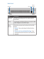
8-Port PoE-Powered Gigabit
Switch with PoE Passthrough
Model: US-8

Introduction
Thank you for purchasing the Ubiquiti Networks® UniFi® 8-Port
PoE-Powered Gigabit Switch with PoE Passthrough. This Quick
Start Guide is designed to guide you through the installation
and also includes the warranty terms.
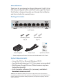
Package Contents
UniFi Switch
Mounting Screws
(Qty. 2)
Screw Anchors
(Qty. 2)
8-Port PoE-Powered Gigabit
Switch with PoE Passthrough
Model: US-8
Power Adapter* Power Cord* Quick Start Guide
* Power Adapter and Power Cord are not included with US-8 5-Pack
System Requirements
• Linux, MacOSX, or Microsoft Windows 7/8/10
• Java Runtime Environment 1.6 (1.8 or newer recommended)
• Web Browser: Google Chrome (Other browsers may have
limited functionality)
• UniFi Controller software v5.3.x (or newer), available at:
downloads.ubnt.com/unifi
TERMS OF USE: All Ethernet cabling runs must use CAT5 (or above). It is the customer’s
responsibility to follow local country regulations, including operation within legal frequency
channels, output power, indoor cabling requirements, and Dynamic Frequency Selection
(DFS) requirements.

Network Topology Requirements
• A DHCP-enabled network for the UniFi Switch to obtain an
IPaddress (connected devices will also obtain IP addresses
after deployment)
• A UniFi Cloud Key or management station running the UniFi
Controller software v5.3 (or newer), located either on-site
and connected to the same Layer2 network, or off-site in a
cloud or NOC
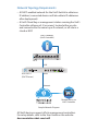
US-8
USG-PRO-4
(DHCP Server)
Internet
LAN
WAN
UniFi Cloud Key
(UniFi Controller)
Remote Access to
UniFi Controller
Sample Network Diagram
All UniFi devices support off-site management controllers.
For setup details, refer to the User Guide on the website:
documentation.ubnt.com/unifi

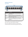
Hardware Overview
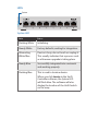
Front Panel
Ports 1-8
PoE OutPoE In
Port Description
Ports 1-8 RJ45 ports support 10/100/1000 Ethernet
connections.
PoE In
(Port 1)
Supports 802.3af/at or 48V Passive PoE to
power the switch and can provide 48V (2-pair)
PoE passthrough to port 8.
PoE Out
(Port 8)
PoE output is Off by default. Enabling PoE
output requires 24W input power via PoE In or
DC input.
The UniFi Switch may be powered by PoE through the PoE In
port or by DC input using a 48V power adapter.
PoE can be enabled on the PoEOut port using the UniFi
Controller software. PoE passthrough supports 48V (2-pair).

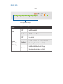
Back Panel
Reset
Button
DC InGround
Port Description
Ground Ancillary grounding point for enhanced ESD
protection.
DC In To power the switch by DC input, connect a 48V
power adapter to the 48VDC port.
Reset
Button
This button serves two functions for the UniFi
Switch:
• Restart Press and release the Reset button
quickly.
• Restore to Factory Default Settings Press
and hold the Reset button for more than five
seconds.

LEDs
System
System LED
State Status
Flashing White Initializing.
Steady White Factory defaults, waiting for integration.
Alternating
White/Blue
Device is busy; do not touch or unplug it.
This usually indicates that a process such
as a firmware upgrade is taking place.
Steady Blue Successfully integrated into a network
and working properly.
Flashing Blue This is used to locate a device.
When you click Locate in the UniFi
Controller software, the System LED
will flash blue. The software will also
display the location of the UniFi Switch
on themap.

RJ45 LEDs
1 2 3 4 5 6 7 8
PoE
Link
DOWN 10/100 1000
OFF 48V
PoE
Link/Speed/Activity
LED
State Status
PoE
Off PoE Disabled
Amber 48V Passive PoE
Link/
Speed/
Activity
Off No Link
Amber
Link Established at 10/100Mbps
Flashing Indicates Activity
Green
Link Established at 1 Gbps
Flashing Indicates Activity

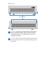
Side Panels
Ventilation Holes
WARNING: FAILURE TO PROVIDE PROPER VENTILATION
MAY CAUSE FIRE HAZARD. KEEP AT LEAST 20 MM OF
CLEARANCE NEXT TO THE VENTILATION HOLES FOR
ADEQUATE AIRFLOW.
WARNING: The US-8 must not be stacked. Do not place it
on top of another switch. Do not place anything on top
of the US-8.

Hardware Installation
The UniFi Switch can be mounted on a vertical surface or
placed on a desktop. Follow the Wall Mounting instructions to
mount the switch using the included screws and anchors.
WARNING: To reduce the risk of fire or electric shock, do
not expose the switch to rain or moisture.
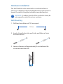
Wall Mounting
1. Drill two 6 mm holes set 73.5 mm apart.
73.5 mm
2. Insert a Screw Anchor into each hole, and fasten a Screw
into each anchor.
3. Leave a clearance of approximately 3mm between the
screw head and the wall.
3 mm

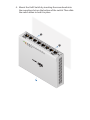
4. Mount the UniFi Switch by inserting the screw heads into
the mounting slots on the bottom of the switch. Then slide
the switch down to lock it in place.

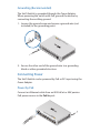
Grounding (Recommended)
The UniFi Switch is grounded through the Power Adapter.
When powering the switch with PoE, ground the device by
connecting the ancillary ground.
1. Loosen the ground screw and secure a ground wire (not
included) to the grounding point.
2. Secure the other end of the ground wire to a grounding
block or other grounded structure.
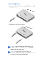
Connecting Power
The UniFi Switch can be powered by PoE or DC input using the
Power Adapter.
Power by PoE
Connect an Ethernet cable from an 802.3af/at or 48V passive
PoE power source to the PoE In port.

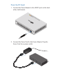
Power by DC Input
1. Connect the Power Adapter to the 48VDC port on the back
of the UniFi Switch.
2. Connect the Power Cord to the Power Adapter. Plug the
Power Cord into a power outlet.

Connecting Ethernet
1. Connect an Ethernet cable from your DHCP server or LAN
to any port 1 to 7.
2. Connect your PoE device to port 8.
WARNING: Before enabling PoE passthrough in the
UniFi Controller, ensure that the connected PoE device
supports the PoE power (48V).
WARNING: When both PoE In and DC Input are
connected, the highest voltage power of the two will
immediately pass through to PoE Out.

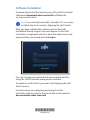
Software Installation
Download and install the latest version of the UniFi Controller
software at downloads.ubnt.com/unifi and follow the
on-screen instructions.
Note: If you already have UniFi Controller v5.3.x or newer
installed, skip to the section, Adopting the UniFi Switch.
After you have installed the software and run the UniFi
Installation Wizard, a login screen will appear for the UniFi
Controller management interface. Enter the admin name and
password that you created and click Log In.
You can manage your network and view network statistics
using the UniFi Controller management interface.
To adopt the UniFi Switch, proceed to the Adopting the UniFi
Switch section.
For information on configuring and using the UniFi
Controller software, refer to the User Guide on the website:
documentation.ubnt.com/unifi
*640-00252-04*
640-00252-04

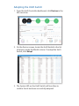
Adopting the UniFi Switch
1. From the UniFi Controller dashboard, click Devices in the
left menu bar.
2. On the Devices screen, locate the UniFi Switch in the list
of devices under the Model column. To adopt the UniFi
Switch, click Adopt.
3. The System LED on the UniFi Switch will turn blue to
confirm that it has been successfully adopted.

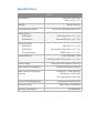
Specifications
US-8
Dimensions 148 x 99.5 x 30.7 mm
(5.83 x 3.92 x 1.21")
Weight 432 g (15.24 oz)
Networking Interfaces (8) 10/100/1000 Mbps RJ45 Ports
PoE In (Port 1)
PoE Mode 1:
PoE Mode 2:
802.3af/at (Pins +1, 2; -3, 6)
Passive 48V (Pins +4, 5; -7, 8)
PoE Out (Port 8)
PoE Mode 1:
PoE Mode 2:
DC Input Mode:
48V (Pins +1, 2; -3, 6)
Passive 48V (2-Pair Pins +4, 5; -7, 8)
48VDC (Pins +1, 2; -3, 6)
Power Method (1) DC 48V, Max. 1.25A
(1) PoE Input, 802.3af/at (Pins +1, 2; -3, 6)
Power Supply External AC/DC Adapter: 48V, 0.5A
Max. Power Consumption 12W (Excluding PoE Output)
Max. Passive PoE Wattage
per Port
PoE Mode 1: 12W @ 802.3at
PoE Mode 2: 12W @ 48V
DC Input Mode: 12W @ 48V
Passive PoE Voltage Range Depends on Power Source
Processor Specs ARM Cortex-A9 400 MHz
Memory Information 256 MB DDR3

US-8
Code Storage 32 MB NOR Flash
Line Rate 8 Gbps, Non-Blocking
LEDs
System
RJ45 Data Ports
Status
PoE; Link/Speed/Activity
ESD/EMP Protection ± 24kV Air, ± 24kV Contact
Operating Temperature -5 to 45° C (23 to 113° F)
Operating Humidity 5 to 95% Noncondensing
Certications CE, FCC, IC

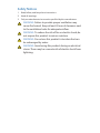
Safety Notices
1. Read, follow, and keep these instructions.
2. Heed all warnings.
3. Only use attachments/accessories specified by the manufacturer.
WARNING: Failure to provide proper ventilation may
cause fire hazard. Keep at least 20 mm of clearance next
to the ventilation holes for adequate airflow.
WARNING: To reduce the risk of fire or electric shock, do
not expose this product to rain or moisture.
WARNING: Do not use this product in location that can
be submerged by water.
WARNING: Avoid using this product during an electrical
storm. There may be a remote risk of electric shock from
lightning.

Electrical Safety Information
1. Compliance is required with respect to voltage, frequency, and current
requirements indicated on the manufacturer’s label. Connection to a
different power source than those specified may result in improper
operation, damage to the equipment or pose a fire hazard if the
limitations are not followed.
2. There are no operator serviceable parts inside this equipment. Service
should be provided only by a qualified service technician.
3. This equipment is provided with a detachable power cord which has
an integral safety ground wire intended for connection to a grounded
safety outlet.
a. Do not substitute the power cord with one that is not the provided
approved type. Never use an adapter plug to connect to a 2-wire
outlet as this will defeat the continuity of the grounding wire.
b. The equipment requires the use of the ground wire as a part of the
safety certification, modification or misuse can provide a shock
hazard that can result in serious injury or death.
c. Contact a qualified electrician or the manufacturer if there
are questions about the installation prior to connecting the
equipment.
d. Protective earthing is provided by Listed AC adapter. Building
installation shall provide appropriate short-circuit backup
protection.
e. Protective bonding must be installed in accordance with local
national wiring rules and regulations.

Limited Warranty
UBIQUITI NETWORKS, Inc (“UBIQUITI NETWORKS”) warrants that the
product(s) furnished hereunder (the “Product(s)”) shall be free from defects
in material and workmanship for a period of one (1) year from the date
of shipment by UBIQUITI NETWORKS under normal use and operation.
UBIQUITI NETWORKS’ sole and exclusive obligation and liability under
the foregoing warranty shall be for UBIQUITI NETWORKS, at its discretion,
to repair or replace any Product that fails to conform to the above
warranty during the above warranty period. The expense of removal and
reinstallation of any Product is not included in this warranty. The warranty
period of any repaired or replaced Product shall not extend beyond its
original term.
Warranty Conditions
The above warranty does not apply if the Product:
(I) has been modified and/or altered, or an addition made thereto,
except by Ubiquiti Networks, or Ubiquiti Networks’ authorized
representatives, or as approved by Ubiquiti Networks in writing;
(II) has been painted, rebranded or physically modified in any way;
(III) has been damaged due to errors or defects in cabling;
(IV) has been subjected to misuse, abuse, negligence, abnormal physical,
electromagnetic or electrical stress, including lightning strikes, or
accident;
(V) has been damaged or impaired as a result of using third party
firmware;
(VI) has no original Ubiquiti MAC label, or is missing any other original
Ubiquiti label(s); or
(VII) has not been received by Ubiquiti within 30 days of issuance of
the RMA.
In addition, the above warranty shall apply only if: the product has been
properly installed and used at all times in accordance, and in all material
respects, with the applicable Product documentation; all Ethernet cabling
runs use CAT5 (or above), and for outdoor installations, shielded Ethernet
cabling is used, and for indoor installations, indoor cabling requirements
are followed.
Returns
No Products will be accepted for replacement or repair without obtaining
a Return Materials Authorization (RMA) number from UBIQUITI NETWORKS
during the warranty period, and the Products being received at UBIQUITI
NETWORKS’ facility freight prepaid in accordance with the RMA process of
UBIQUITI NETWORKS. Products returned without an RMA number will not
be processed and will be returned freight collect or subject to disposal.
Information on the RMA process and obtaining an RMA number can be
found at: www.ubnt.com/support/warranty.
Pagina se încarcă...
Pagina se încarcă...
Pagina se încarcă...
Pagina se încarcă...
Pagina se încarcă...
Pagina se încarcă...
Pagina se încarcă...
Pagina se încarcă...
-
 1
1
-
 2
2
-
 3
3
-
 4
4
-
 5
5
-
 6
6
-
 7
7
-
 8
8
-
 9
9
-
 10
10
-
 11
11
-
 12
12
-
 13
13
-
 14
14
-
 15
15
-
 16
16
-
 17
17
-
 18
18
-
 19
19
-
 20
20
-
 21
21
-
 22
22
-
 23
23
-
 24
24
-
 25
25
-
 26
26
-
 27
27
-
 28
28


Ubiquiti unifi switch 8 Ghid de inițiere rapidă
- Tip
- Ghid de inițiere rapidă
- Acest manual este potrivit și pentru
în alte limbi
- English: Ubiquiti unifi switch 8 Quick start guide
- italiano: Ubiquiti unifi switch 8 Guida Rapida
Lucrări înrudite
-
Ubiquiti UniFi UAP-IW-HD Ghid de inițiere rapidă
-
Ubiquiti UAP-PRO Ghid de inițiere rapidă
-
-
-
-
-
-
-
-