
Please read the operating instructions carefully before using this product, and keep the operating
instructions for future use.
See page 63 for all model numbers.
Operating Instructions
Ultra-Low Temperature Freezer
MDF-DU702VH

2
CONTENTS
INTRODUCTION ········································································· 3
PRECAUTIONS FOR SAFE OPERATION ········································· 4
LABELS ON UNIT ········································································ 9
SYMBOLS ON UNIT ····································································· 9
ENVIRONMENTAL CONDITIONS ················································· 10
INTENDED USE AND PRECAUTIONS ··········································· 10
FREEZER COMPONENTS
Main body ············································································ 11
LCD touch panel ··································································· 13
Remote alarm terminal ··························································· 15
Air intake port (Manual) ·························································· 15
INSTALLATION SITE ·································································· 16
INSTALLATION ········································································· 17
START-UP PROCEDURE ··························································· 19
DURING/AFTER POWER FAILURE
Operation during power failure ················································· 20
Operation after recovery from power failure ································· 20
BASIC OPERATION ON LCD TOUCH PANEL ································· 21
BASIC PARAMETERS
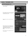
How to input numerical value and alphanumeric character ·············· 22
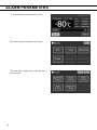
Setting Temperature, High Alarm and Low Alarm ························· 24
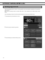
Setting operation control mode ················································· 25
Setting key lock ···································································· 26
Removing key lock ································································· 29
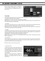
ALARM PARAMETERS ······························································ 30
OPERATION/ALARM LOG
Setting log interval ································································· 32
Displaying operation log ·························································· 33
Exporting operation log ·························································· 36
Displaying alarm log ······························································· 39
Exporting alarm log ································································ 41
OTHER PARAMETERS
Setting date and time······························································ 44
Setting brightness and sleep ···················································· 45
ALARMS AND SELF-DIAGNOSIS ················································· 47
ROUTINE MAINTENANCE
Cleaning the exterior, interior, and accessories ···························· 50
Cleaning of air intake port (Manual) ··········································· 50
Cleaning of condenser filter ····················································· 51
Defrosting of chamber ··························································· 52
CALIBRATION ·········································································· 52
REPLACEMENT OF WORN-OUT PARTS
Replacing the battery for power failure alarm ······························· 53
Replacing the battery for backup cooling kit ································ 53
TROUBLESHOOTING ································································ 54
DISPOSAL OF UNIT ·································································· 55
Recycle of battery ································································· 55
OPTIONAL COMPONENTS
Temperature recorder ···························································· 60
Small inner doors ·································································· 60
Inventory rack ······································································ 60
Back-up cooling kit ································································ 61
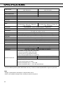
SPECIFICATIONS ····································································· 62
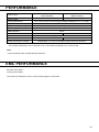
PERFORMANCE ······································································· 63
EMC PERFORMANCE ······························································· 63
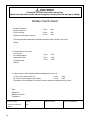
SAFETY CHECK SHEET····························································· 64

3
INTRODUCTION
■ Read the operating instructions carefully before using the product and follow the instructions for safe
operation.
■ PHC Corporation takes no responsibility for safety if the product is not used as intended or is used with
any procedures other than those given in the operating instructions.
■ Keep the operating instructions in a suitable place so that they can be referred to as necessary.
■ The operating instructions are subject to change without notice for improvement of performance or
function.
■ Contact our sales representative or agent if any page of the operating instructions is lost or the page
order is incorrect, or if the instructions are unclear or inaccurate.
■ No part of the operating instructions may be reproduced in any form without the express written
permission of PHC Corporation.
IMPORTANT NOTICE
PHC Corporation guarantees this product under certain warranty conditions. However, please note that
PHC Corporation shall not be responsible for any loss or damage to the contents of the product.

4
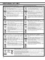
PRECAUTIONS FOR SAFE OPERATION
It is imperative that the user complies with the operating instructions
as they contain important safety advice.
Items and procedures are described so that you can use this unit correctly and safely.
Following these precautions will prevent possible injury to the user and any other
person.
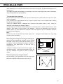
Precautions are illustrated in the following way:
WARNING
Warning indicates a potentially hazardous situation which, if not avoided,
could result in serious injury or death.
CAUTION
Failure to observe CAUTION signs could result in injury to personnel and
damage to the unit and associated property.
Symbols have the following meanings:
T
his symbol means caution.
This symbol means an action is prohibited.
This symbol means an instruction must be followed.
Be sure to keep the operating instructions in a place that is accessible to users of this
unit.

5
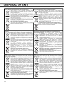
PRECAUTIONS FOR SAFE OPERATION
Do not use the unit outdoors. Exposure to rain may cause leakage and/or electric shock.
Only qualified engineers or service personnel should install the unit. Installation by unqualified
personnel may cause electric shock or fire.
Install the unit in a location capable of bearing the total combined weight (product + optional
accessories + stored items). After installing the unit, be absolutely sure to take precautions
to prevent the unit from falling over. If the unit is installed in a location which is not strong enough
or if the proper precautions are not taken, the unit may fall over and cause injuries.
Do not install the unit where there are high levels of moisture or where it may be splashed with
water. Installing the unit where there are high levels of moisture or where it may be splashed with
water may cause the insulation to deteriorate and give rise to leakage and/or electric shock.
Do not install the unit in a location where flammable or volatile substances are present.
Installing the unit in a location where flammable or volatile substances are present may cause
explosions and/or a fire.
Do not install the unit in a location where corrosive gases such as acids are present. Installing
the unit in a location where corrosive substances are present may cause electrical components to
corrode, leading to leakage and/or electric shock due to the deterioration of insulation resulting from
corroded electrical components.
Do not place this unit in a location where it is difficult to disconnect the power supply plug.
Failure to disconnect the power supply plug may cause fire in the event of a problem or malfunction.
Be absolutely sure to earth (ground) the unit to prevent electric shock. Failure to earth the
product may give rise to electric shock. If necessary, ask a qualified contractor to do this work.
Do not connect the earth wire to a gas pipe, water pipe or lightning rod when earthing the
unit. Earthing the unit improperly may give rise to electric shock.
Connect the unit to a power source as indicated on the rating label attached to the unit. Use
of any other voltage or frequency other than that on the rating label may cause fire or electric shock.
Never store volatile or flammable substances in this unit except in a sealed container. Such
substances may cause explosion or fire if they leak.
Never insert metal objects such as pins and wires into any vent, gap, or outlet on the unit.
This may cause electric shock or injury by accidental contact with moving parts.
WARNING

6
PRECAUTIONS FOR SAFE OPERATION
When handling harmful samples (for example, those which consist of toxic, pathogenic or
radioactive substances), install the unit inside a designated isolation facility. If the unit is
installed in a location which is not an isolation facility, there may be detrimental effects on both people
and the natural environment.
Before proceeding with maintenance or checking the unit, set the power switch to OFF, and
disconnect the power supply plug. Performing the work while power is still flowing to the product
or while the power supply plug is still connected may give rise to electric shock and/or injury.
Do not touch any electrical parts (such as power supply plug) or operate switches with a wet
hand. This may cause electric shock.
Wear protective gloves and mask during maintenance. Touching or inhaling chemicals or
aerosols from around the unit may be detrimental to health.
Never splash water directly onto the unit as this may cause electric shock or short circuit.
Never put containers with liquid on top of the unit as this may cause electric shock or short circuit
if the liquid is spilled.
Never damage the power supply cord or power supply plug (by breaking, adapting, placing
near a source of heat, bending with force, twisting, pulling, adding weight, or binding). A
damaged power supply cord or power supply plug may cause electric shock, short circuit, or fire
Never disassemble, repair, or modify the unit yourself. A high-voltage area is located inside the
unit. Any work carried out by unauthorized personnel may result in electric shock. Contact our
sales representative or agent for maintenance or repair.
Make sure the power supply plug is pushed fully in. Faulty insertion of the power supply plug
may cause electric shock or fire due to generation of heat. Never use a damaged power supply plug
or loose power outlet
Disconnect the power supply plug if there is anything wrong with the unit. Continued abnormal
operation may cause electric shock or fire.
Grip the power supply plug when disconnecting the power supply cord from the outlet.
Pulling the power supply cord may cause electric shock or short circuit.
Remove dust from the power supply plug periodically. Dust on the power supply plug may
cause insulation failure due to moisture and thus cause a fire. Disconnect the power supply plug and
wipe it with a dry cloth
WARNING

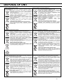
7
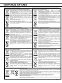
PRECAUTIONS FOR SAFE OPERATION
Disconnect the power supply plug before moving the unit. Take care not to damage the power
supply cord. A damaged power supply cord may cause electric shock or fire.
Disconnect the power supply cord when the unit is not in use for long periods. Keeping the
unit connected may cause electric shock, leakage, or fire due to the deterioration of insulation.
If the unit is to be stored unused in an unsupervised area for a long period, ensure that children do
not have access and that doors cannot be closed completely.
Ask a qualified contractor to carry out disassembly and disposal of the unit. Leaving the unit in
a location that can be accessed by third parties may result in unexpected accidents (e.g. the unit may
be used for unintended purposes).
Do not leave the plastic bags used for packing in a place where they can be reached by small
children as this may result in unexpected accidents such as suffocation.
Never replace the battery for the power-failure alarm yourself. Only qualified engineers or
service personnel should replace the battery.
When moving the unit, be sure to take precautions to prevent it from falling over. Moving the
unit with too much force may cause it to fall over, possibly resulting in injury. A qualified individual
must be assigned to supervise the safe movement and relocation of the unit.
Install the unit in a well-ventilated (airy) location to prevent the accumulation of flammable
refrigerant. The flammable refrigerant may cause fire if it leaks.
Never damage the chamber wall or pipework in the chamber when removing frost. The
refrigerant is flammable and may cause a fire if it leaks.
Flammable and explosive product. The unit contains flammable refrigerant. When repairing or
recycling, only trained service personnel will repair and follow the procedure below.
Well ventilate the room to prevent refrigerant accumulation.
Keep fire away when the refrigerant is contained in the product.
Do not damage or break the pipework.
As with any equipment that uses CO2 gas, there is a likelihood of oxygen depletion in the vicinity of the
equipment. It is important that you assess the work site to ensure there is suitable and sufficient
ventilation. If lack of ventilation is suspected, then other methods of ensuring a safe environment
must be considered. These may include atmosphere monitoring systems and warning devices with
alarms.
Do not touch the condenser directly when the filter is removed for cleaning. Touching the
condenser may cause injury due to its hot surface.
WARNING

8
PRECAUTIONS FOR SAFE OPERATION
Never install the unit in a location where corrosive materials such as sulphur compounds are
likely to be generated (e.g. near a drainage facility). Corrosion of the copper pipes may result in
the deterioration and consequently the failure of the cooling unit.
This unit must be plugged into a dedicated circuit protected by branch circuit breaker.
Use a dedicated power source as indicated on the rating label attached to the unit. A
multiple-tap may cause fire resulting from abnormal heating.
Do not climb on top of the unit or put any objects on the unit. Falling from the unit may cause
injury; falling objects may cause damage to the unit.
Never store corrosive substances such as acids or alkalis in this unit except in a sealed
container. These may be harmful to your health and may cause corrosion of internal components or
electrical parts.
Check the settings when restarting operation after a power failure or after turning the power off.
The settings may have changed as a result of stopping the unit. Stored items inside the unit may be
adversely affected when operation is resumed if the settings have changed.
To ensure the safety of the service engineer, submit a safety check sheet with the required
items filled out. This is provided as the photocopiable “Safety Check Sheet” at the end of these
operating instructions
Use designated parts for parts replacement. Using an incorrect part may cause fire.
Do not give strong shock or vibration during movement or use. The piping may be damaged,
causing a fire.
Turn the leveling feet to separate the casters from the floor and secure the unit. If they are left
touching the floor, the unit may inadvertently move out of position when its door is opened or
closed. It may cause injury.
CAUTION

9
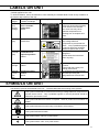
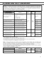
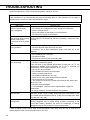
LABELS ON UNIT
<Labels applied to the unit>
To avoid accidents, users are advised to read carefully the hazard labels found at key locations on
the interior and exterior of the unit.
Possible
Danger
Warning/Caution Type
Location of Danger
Warning/Caution Label Description of Danger
Personal
injury
Sample
damage
Frostbite
Rise in chamber
temperature
Interior
To prevent frostbite, wear
protective gloves when handling
frozen items in the chamber.
Too much frost may cause
chamber temperature rise
resulting from incomplete door
close.
Personal
injury
Electric shock
Electric box
Attached to covers that access
high-voltage electrical
components to prevent electric
shock. Only a qualified engineer
or service personnel should be
allowed to open these covers.
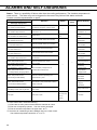
Personal
injury
Flammable and
explosive product
Interior
This product contains flammable
refrigerant.
Please follow the instructions
when recycling.
Sample
damage
Chamber temperature
Interior
Clean the filter about every once
a month.
A dusty filter may cause poor
cooling performance.
Damage
of outer
door
latch
Negative pressure
release
Interior
Ice should be removed from the
air intake port using the
designated frost removal stick.
SYMBOLS ON UNIT
The following symbols are attached to the unit. The table describes the meaning of the symbols.
This symbol is attached to covers that access high-voltage electrical components to
prevent electric shock. Only a qualified engineer or service personnel should be
allowed to open these covers.
This symbol indicates that caution is required. Refer to product documentation for
details.
This symbol indicates Incorrect usage could lead to a fire hazard.
This symbol indicates an earth.
This symbol means “ON” for a power switch.
This symbol means “OFF” for a power switch.

10
ENVIRONMENTAL CONDITIONS
This equipment is designed to be safe at least under the following conditions (based on the IEC 61010-1):
■ Indoor use;
■ Altitude up to 2000 m;
■ Temperature 5 oC to 40 oC;
■ Maximum relative humidity 80 % for temperature up to 31 oC decreasing linearly to 50 % relative
humidity at 40 oC;
■ Mains supply voltage fluctuations up to ±10 % of the nominal voltage;
■ Transient overvoltages up to the levels of OVERVOLTAGE CATEGORY II;
■ Temporary OVERVOLTAGES occurring on the mains supply;
■ Applicable pollution degree of the intended environment (POLUTION DEGREE 2 in most cases);
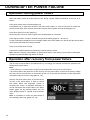
INTENDED USE AND PRECAUTIONS
This equipment is designed for low temperature storage of human cells, organs, plasma and DNAs.
Temperature and duration of storage:
cells: 1month - 1year at -80 °C
organs: 11months at -80 °C
DNA: Long term (8 years) at -80 - -70 °C
plasma: 2-3 months at -80 °C
■ The effective storage period depends on the sample condition and storage temperature. It is
necessary to determine the storage temperature and period suitable for the purpose.
■ For the live cells, the lower storage temperature should be required for long term storage. It is
recommended to store the live cells at -130 oC or lower.

11
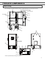
FREEZER COMPONENTS
Main body
The model below is the MDF-DU702VH. However, the MDF-DU502VH is also equivalent structures.
* When an optional backup cooling kit is installed.
・ON
OFF
+
POWER
7
3
11
18
20 (inside)
12
16
17
5
15* 14* 13*
19
10
10
Door gaske
t
4
2
1
Outer door
6
8
9
20 (Inside the outer door)
21

12
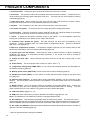
FREEZER COMPONENTS
1. Inner door latch: Always lock the inner door latch when the inner door is closed.
2. Inner door: This prevents cold air from escaping when the outer door is opened. Always be sure to
close the inner door securely before closing the outer door. The inner door can be removed for cleaning
or defrosting [page 52].
3. Outer door latch: When closing the outer door push the latch until the latch is locked in place.
Provision has been made for use of an additional padlock (not included).
4. Keyhole: Turn clockwise to 180o with a key and the outer door is securely locked.
5. Air intake vent (grille): Do not block this vent to keep the proper cooling performance.
6. Leveling feet: These are screw bolts used to install and fix the unit. Adjust the height of the leveling
feet by turning the screw bolts until 2 front casters are away from the floor.
7. Caster: 4 casters are provided to facilitate moving of the cabinet. For the installation, adjust the
leveling feet so that the front 2 casters cannot contact with the floor.
8. Condenser filter (behind the grille): This filter prevents the dust from accumulating on the
condenser. A dusty condenser filter may cause failure of refrigerating device. Clean the condenser
filter once a month [page 51].
9. Space for temperature recorder: A temperature recorder (optional) can be mounted here so that
the chamber temperature can be recorded automatically [page 60].
10. Access port (rear and bottom): These ports are used to pass the sensor or cable of measuring
equipment, the sensor of a temperature recorder (optional), or the nozzle of a back-up cooling kit
(optional) to the chamber.
11. Fixture (on back side): Use the fixtures and secure the unit to a wall with a strong rope or chain
[page 17].
12. Power switch: This is the power switch of the unit. (ON=“l”,OFF=“○”)
13. Temperature setting knob (TEMP. SET)*: It is the knob which adjusts injection set temperature of
the backup cooling kit [page 61].
14. Backup power switch (BACK UP)*: Power switch of the backup cooling kit [page 61].
15. Backup test switch (TEST)*: It is the switch to confirm that the backup cooling kit can inject liquid
CO2 [page 61].
16. Remote alarm terminal: A remote alarm device (separately available) can be connected to this
terminal. The remote alarm relays the alarm to an operator in a remote location if the unit is un attended
[page 15].
17. Battery switch: This is an ON-OFF switch for the battery for the power-failure alarm. Always turn
this switch on when the unit is operating to ensure that the power-failure alarm is working. Turn this
switch off when the unit is not used for a long period in order to protect the battery.
18. LCD touch panel: [pages 13 - 14]
19. USB port: Insert USB memory to export operations and alarms log [pages 36 - 43].
Note: It is impossible to use USB memory which is required password input.
20. Air intake port: This operates automatically when the outer door is closed. The outer door can be
opened easily because this port intakes the outer air and the pressure difference between the chamber and
outside is deleted. During the operation of this port, the suction noise arises, but this is not a malfunction.
21. Air intake port (Manual): Adjust the pressure difference inside and outside the chamber manually to
open the outer door smoothly [page 15].
* When an optional backup cooling kit is installed.

13
FREEZER COMPONENTS
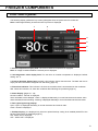
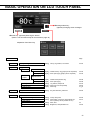
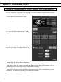
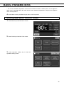
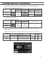
LCD touch panel
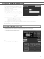
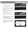
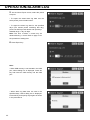
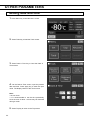
The following display (called the Top screen) will appear when the power switch is turned ON.
Note: It takes approximately 20 seconds until Top screen is displayed.
1 2 3
4
5
6
7
1. Present temperature display field: The current chamber temperature is displayed.
Note: An integer rounded off below a decimal point is displayed.
2. Set temperature value display field: The set value of chamber temperature is displayed. Default
setting: -80 oC.
3. Present date/time display field: Normally, this indicator shows date and time. The date and time is
simply set when the freezer is shipped from the factory [page 44].
4. Filter alarm indicator: This indicator is lit when the excessive dust is accumulated on the condenser
filter. When this indicator is lit, clean the condenser filter following the procedure [page 51].
5. Alarm display: [pages 47 - 48]
Normal condition: “Normal” is displayed.
Alarm-activated, buzzer-delayed: “Alarm” is displayed alternately in normal characters and reverse video.
Alarm-activated, buzzer-sounding: “Warning” is displayed alternately in normal characters and reverse video.
6. Door (opening/closing) display:
Open: “Open” is displayed alternately in normal characters and reverse video.
Close: “Closed” is displayed.
7. Backup display: (It is displayed only when an optional backup cooling kit is installed) ON/OFF of the
backup power switch is displayed [page 61].
ON: “Switch ON” is displayed.
OFF: “Switch OFF” is displayed.

14
FREEZER COMPONENTS
8
11 10
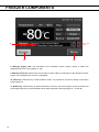
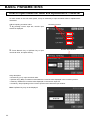
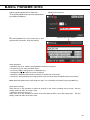
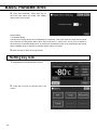
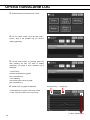
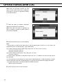
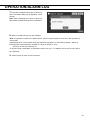
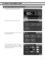
8. Message display field: The information of the operation monitor system, alarms or status are
displayed when fault occurs [pages 47 -48].
9. Message select key: When there are a number of alarm, status or information of the operation monitor
system, the message on the screen is changeable.
10. Menu key: Press this key to lead the Menu screen. It is possible to set various setting on the Menu
screen [page 21].
11. Buzzer key: Press this key to silence the buzzer. However, when the ring back is ON, the buzzer will
sound again when the ring back passed and the alarm state still continues [pages 30 - 31 and 49].
9

15
FREEZER COMPONENTS
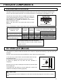
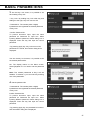
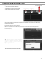
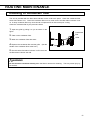
Remote alarm terminal
The alarm of this unit can be informed at a remote location from this unit by connecting the external alarm
device to the remote alarm terminals. For the type and behavior of remote alarm output [pages 47 - 48].
The terminal of the remote alarm is installed at the right side
of the unit (See the figure on the point). The alarm is outputted
from this terminal. Contact capacity is DC 30 V, 2 A.
When Buzzer key is pressed, the behavior of the remote
alarm is showed in Table.1.
Note: In the door alarm, the remote alarm does not work
[page 48].
Table 1 The behavior of the remote alarm when pressing Buzzer key
Remote Alarm setting
[pages 30 – 31]
Connecting
terminal
Normal
condition
Abnormal condition
(Including in the cases of power outage and
of where the power plug is pulled out.)
When pressing Buzzer key
ON:
Non-interlock with Buzzer key
COM.-N.C. Close Open Open (Maintain in abnormality)
COM.-N.O. Open Close Close (Maintain in abnormality)
OFF:
Interlock with Buzzer key
COM.-N.C. Close Open Close (Return to normal)
COM.-N.O. Open Close Open (Return to normal)
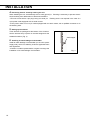
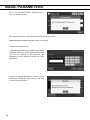
Air intake port (Manual)
The difference in pressure inside and outside of the chamber is adjusted automatically to open the outer door
smoothly.
However, if the door becomes heavy and difficult to open, follow the procedure below.
1. Turn the cap on the left side counterclockwise about two laps.
(Or remove the cap.)
2. Allow about twenty seconds before open the outer door.
3. Close (or replace) the cap when the door operation is
completed.
Remove the cap on the air intake port and check for the frost inside
the air intake port.
If excessive frost has built up in the air intake port, remove with
a"Stick for air intake port cleaning" [page 50].
CAUTION
For removing the frost in the air intake port, do not use a tool with sharp edge such as a knife or a screw
driver.
Remote alarm terminal
About 2 laps
Cap
Use a twisted shielded wire for the connection.
Type; UL 2343, UL 2448, UL 2464, UL2552, UL2623.
Length: 30 m max.

16
INSTALLATION SITE
This unit must be installed in a location which meets all the conditions described below.
If the unit is installed in a location which does not meet the conditions, its specified performance may
not be achieved or malfunctions and accidents may occur.
■ A location not exposed to direct sunlight
Avoid any location which is exposed to direct sunlight. Installing the unit in a location exposed to direct
sunlight may reduce its cooling performance.
■ A well-ventilated (airy) location
In order to ensure ventilation, leave clearances of at least 10 cm around the unit (at the left, right, top and
back). Blocking the ventilation may reduce the unit’s cooling performance or cause malfunctions.
■ A location away from sources of heat
Avoid any location which is close to a major source of heat (such as a heater or boiler). Installing the
unit near a major source of heat may reduce the unit’s cooling performance.
■ A location with minimal changes in temperature
Avoid any location where the ambient temperature is subject to sudden changes. If the unit is installed
in a location where the ambient temperature is subject to sudden changes, it will not be possible to
achieve a stable cooling performance.
■ A flat surface where the floor is also capable of bearing the total combined weight (product +
optional accessories + stored items)
Install the unit on a flat surface which is even and which is capable of bearing the total combined weight
(product + optional accessories + stored items). If the unit is installed where the surface is uneven or
where the unit will be inclined at an angle, the unit will be unstable, and accidents or injuries may occur
and/or unnecessary vibration or noise may be generated.
■ A location with minimal humidity
Install the unit in a location where the relative humidity is less than 80 %R.H. Installing the unit in a very
humid location may cause earth faults and/or electric shock.
■ A location free of flammable or corrosive gases
Avoid any location exposed to flammable or corrosive gases. Flammable or corrosive gases can cause
explosions and/or a fire. Furthermore, corrosion of the electrical parts may cause the insulation to be
reduced and result in earth faults and/or electric shock.
■ A location where nothing can fall onto the unit
Avoid locations where objects may fall onto the unit. Objects falling and hitting the unit may cause it to
break down or fail.

17
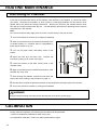
INSTALLATION
When installing the unit, follow the steps below to secure the unit properly, and also be absolutely sure to
earth the unit.
In addition, install an earth leakage circuit breaker (on the unit’s power supply side), which is mandatory
under the applicable laws and regulations.
1. Preparations after unpacking
Remove all the tape used to secure the doors and interior parts, and leave the doors open for a short
while for ventilation.
If any surfaces of the outer cabinet are dirty, wipe the surface using a cloth moistened with a diluted
neutral dish-washing detergent.
Using an undiluted solution of detergent may cause the unit’s plastic areas to crack. Follow the
directions on the detergent for details of dilution.
After wiping the unit using the diluted detergent, be absolutely sure to wipe the surfaces with a cloth
dipped in clean water to remove traces of the detergent. After this, be absolutely sure to wipe the
surfaces with a dry cloth, allowing the surfaces of the outer cabinet to dry out completely, and then
proceed with the installation.
Note:
Remove the cable tie that bands the power supply cord. Prolonged contact with the tie may cause
corrosion of the cord coating.
2. Securing and levelling the unit using the levelling feet
Rotate the front levelling feet clockwise until the casters
are raised 5 mm to 10 mm above the floor surface. (Fig. 1)
In addition, rotate the levelling feet slightly clockwise or
anticlockwise, and adjust them so that the unit is
completely level.
When the casters are raised from the floor surface, the
unit will be secured. If they are left touching the floor, the
unit may accidently move when its door is opened or
closed.
3. Securing the unit by using the fixtures
Use the fixtures on the rear panel of the unit, and secure
the unit to a wall with a strong rope or chain. (Fig. 2)
Fig.1
Levelling feet
Fig. 2
Fixture

18
INSTALLATION
4. Preventing electric shock by earthing the unit
When installing the unit, be absolutely sure to earth (ground) it. Earthing is necessary to prevent electric
shock resulting from deterioration of electrical insulations
This unit comes with a 3-pin plug having one earth pin. Earthing work is not required in the case of a
3-pin power outlet equipped with an earth contact.
If the power outlet is not a 3-pin outlet equipped with an earth contact, ask a qualified contractor to do
the earthing work.
5. Setting up the shelves
Three shelves are packaged at the bottom of the chamber.
Set the shelves firmly in place on the shelf stoppers at the
standard locations. (Fig. 3)
6. Installing an earth leakage circuit breaker
Install an earth leakage circuit breaker (on the unit’s power
supply side), which is mandatory under the applicable laws
and regulations.
Contact our sales representative or agent to arrange the
installation of an earth leakage circuit breaker.
Shelf stopper
Fig. 3

19
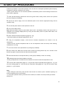
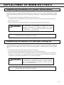
START-UP PROCEDURE
Follow this procedure for the initial operation of the unit and for consequent operations (after temporary
stoppage for cleaning, maintenance or moving).
After a power failure, the unit will restart operation automatically with the same settings as before the
power failure. [page 20],
1. Check that the following switches are turned off: [power switch, battery switch, switch of the optional
back-up cooling kit (if installed)].
2. Connect the power supply cord to the dedicated power source with the appropriate rating with the
chamber empty.
3. Turn ON the power switch to start operation of the unit.
4. Turn on the battery switch.
Note: When the battery switch for power failure alarm is OFF, “S20: Battery Inactive, SW may be OFF.” is
displayed in the message display field. By turning ON the battery switch for power failure alarm, this
message disappears.
5. Set the desired chamber temperature [pages 24 - 25].
The factory setting of chamber temperature is -80 oC.
6. Using the temperature display, check that the chamber temperature has cooled to the set
temperature.
Check that the chamber temperature falls to the set temperature when the start-up after cleaning,
maintenance or moving.
7. Turn on the switch of the optional back-up cooling kit (if installed).
8. Do the alarm test. Make sure that the buzzer sounds by pressing Buzzer key for 5 seconds. Press
Buzzer key again to stop the buzzer and the alarm test finishes.
9. Press the test switch of the optional back-up cooling kit (if installed) to check it is working.
10. Gradually place the material inside the chamber.
Putting a large amount of material into the chamber at one time causes the temperature to rise.
11. Set the alarm temperature [pages 24 – 25] and the buzzer suspended period [pages 30 - 31], lock
the menu setting [pages 26 - 28], and set the compressor delay [pages 25 - 26], and door alarm delay
[pages 30 - 31] as required.
Note:
• When closing the outer door push the latch until the latch is locked in place. Insufficient pushing can
lead to temperature rise in the chamber.
• In case some optional inventory racks are in the chamber, be careful not to drop inventory rack when
pulling out it.

20
DURING/AFTER POWER FAILURE
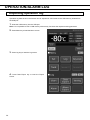
Operation during power failure
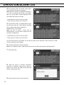
When the battery switch for power failure is ON, during a power failure the behavior of this unit is as
follows.
●The power failure alarm is activated [page 47].
Press Buzzer key to silence the buzzer of the power failure alarm. In case the ring back is turned ON,
buzzer sounds again when a power failure still continues after ring back set time passed [page 31].
●LCD touch panel is turn OFF [page 47].
By touching the LCD touch panel, it lights in the set brightness for 5 seconds.
●The High/Low Alarm is ready to activate during a power failure [pages 24 - 25 and 47].
An alarm message is displayed on the message display field. Alarm display, the buzzer and the remote alarm
as the power failure alarm are being activated.
●The clock function does not stop.
●Operation log data and alarm log data during a power failure is saved.
Note: When the capacity of the battery for power failure alarm is flat during a power failure, subsequent
operation log data and alarm log data is not saved.
Operation after recovery from power failure
The set value is memorized by nonvolatile memory. Accordingly, the chamber resumes the operation with
setting before power failure.
Note:
• It may take up to 1 minute until the LCD touch panel lights after recovery from power failure.
• All products start at the same time as the recovery from the power failure, so that, the temporary voltage
drop may have a bad influence on the starting of this unit. To prevent this situation, set the appropriate
compressor delay time of this unit [pages 25 - 26].
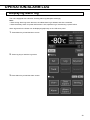
Although the power failure alarm is canceled at the
recovery of the power failure, in order to remind
that power failure had happened, buzzer is
sounding and “Alarm” is displayed alternately in
normal characters and reverse video in the alarm
display [page 49]. By pressing Buzzer key, the
alarm display returns to “Normal” and the buzzer
stops.
Note: It is possible to confirm the past alarms in
the “Displaying alarm log” [pages 39 - 40].
Pagina se încarcă...
Pagina se încarcă...
Pagina se încarcă...
Pagina se încarcă...
Pagina se încarcă...
Pagina se încarcă...
Pagina se încarcă...
Pagina se încarcă...
Pagina se încarcă...
Pagina se încarcă...
Pagina se încarcă...
Pagina se încarcă...
Pagina se încarcă...
Pagina se încarcă...
Pagina se încarcă...
Pagina se încarcă...
Pagina se încarcă...
Pagina se încarcă...
Pagina se încarcă...
Pagina se încarcă...
Pagina se încarcă...
Pagina se încarcă...
Pagina se încarcă...
Pagina se încarcă...
Pagina se încarcă...
Pagina se încarcă...
Pagina se încarcă...
Pagina se încarcă...
Pagina se încarcă...
Pagina se încarcă...
Pagina se încarcă...
Pagina se încarcă...
Pagina se încarcă...
Pagina se încarcă...
Pagina se încarcă...
Pagina se încarcă...
Pagina se încarcă...
Pagina se încarcă...
Pagina se încarcă...
Pagina se încarcă...
Pagina se încarcă...
Pagina se încarcă...
Pagina se încarcă...
Pagina se încarcă...
Pagina se încarcă...
Pagina se încarcă...
Pagina se încarcă...
Pagina se încarcă...
-
 1
1
-
 2
2
-
 3
3
-
 4
4
-
 5
5
-
 6
6
-
 7
7
-
 8
8
-
 9
9
-
 10
10
-
 11
11
-
 12
12
-
 13
13
-
 14
14
-
 15
15
-
 16
16
-
 17
17
-
 18
18
-
 19
19
-
 20
20
-
 21
21
-
 22
22
-
 23
23
-
 24
24
-
 25
25
-
 26
26
-
 27
27
-
 28
28
-
 29
29
-
 30
30
-
 31
31
-
 32
32
-
 33
33
-
 34
34
-
 35
35
-
 36
36
-
 37
37
-
 38
38
-
 39
39
-
 40
40
-
 41
41
-
 42
42
-
 43
43
-
 44
44
-
 45
45
-
 46
46
-
 47
47
-
 48
48
-
 49
49
-
 50
50
-
 51
51
-
 52
52
-
 53
53
-
 54
54
-
 55
55
-
 56
56
-
 57
57
-
 58
58
-
 59
59
-
 60
60
-
 61
61
-
 62
62
-
 63
63
-
 64
64
-
 65
65
-
 66
66
-
 67
67
-
 68
68


Phcbi MDF-DU502VH-PE Instrucțiuni de utilizare
- Tip
- Instrucțiuni de utilizare
- Acest manual este potrivit și pentru
în alte limbi
Lucrări înrudite
-
Phcbi MDF-DU700ZH-PE Instrucțiuni de utilizare
-
-
-
-
-
-
-
-
-