


1
CONTENTS
INTRODUCTION .......................................................................................... 3
INTENDED USE AND PRECAUTIONS ........................................................ 3
PRECAUTIONS FOR SAFE OPERATION ................................................... 4
LABELS ON INCUBATOR ............................................................................ 8
SYMBOLS ON INCUBATOR ........................................................................ 9
ENVIRONMENTAL CONDITIONS ................................................................ 9
INCUBATOR COMPONENTS
Unit .......................................................................................................... 10
LCD touch panel ...................................................................................... 12
Remote alarm terminal ............................................................................ 14
INSTALLATION
Installation site ......................................................................................... 15
Installation ............................................................................................... 17
Connecting CO2 gas cylinder .................................................................. 20
BEFORE COMMENCING OPERATION
Initial cleaning method ............................................................................ 21
Removing inner attachments ................................................................... 22
Installing inner attachments ..................................................................... 24
Filling humidifying pan ............................................................................. 25
FOR BETTER CULTIVATION
Precautions for cultures .......................................................................... 26
Preventing contamination ........................................................................ 27
CORRECT OPERATION ............................................................................ 28
BASIC OPERATION ON LCD TOUCH PANEL .......................................... 30
BASIC PARAMETERS
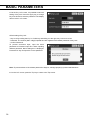
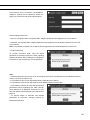
Numerical input to input window ............................................................. 32
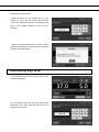
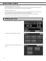
Setting temperature, CO
2
density and high limit temperature alarm
............ 33
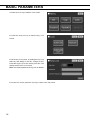
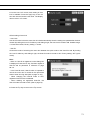
Setting key lock ....................................................................................... 35
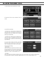
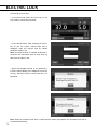
Removing key lock .................................................................................. 37
ALARM PARAMETERS .............................................................................. 39
OPERATION/ALARM/STERILISATION LOG
Setting log interval ................................................................................... 42
Displaying operation log .......................................................................... 43
Exporting operation log ........................................................................... 47
Displaying alarm log ................................................................................ 50
Exporting alarm log ................................................................................. 52
Displaying sterilisation log ....................................................................... 55
Exporting sterilisation log ........................................................................ 57
OTHER PARAMETERS
Setting date and time .............................................................................. 60
Setting brightness and sleep ................................................................... 61

2
CONTENTS
DRY HEAT STERILISATION ...................................................................... 63
Dry heat sterilisation ................................................................................ 63
ELECTRIC LOCK ....................................................................................... 68
Setting User-ID ........................................................................................ 68
Setting auto lock ...................................................................................... 70
Using unlock key ..................................................................................... 73
Removing auto lock ................................................................................. 74
UV LAMP PARAMETERS ........................................................................... 75
Using UV lamp ........................................................................................ 75
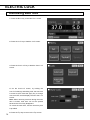
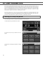
Setting UV lamp ON period ..................................................................... 76
Lighting UV lamp for 24 hours ................................................................. 78
GAS AUTO CHANGER (OPTION) ............................................................. 80
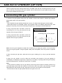
Connecting CO2 gas cylinder .................................................................. 80
Automatic CO2 gas supply line changeover ............................................ 81
Manual CO2 gas supply line A/B changeover ......................................... 83
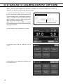
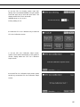
STD GAS AUTO CALIBRATION KIT (OPTION) ......................................... 84
ROUTINE MAINTENANCE ........................................................................ 87
ALARMS, SAFETY, AND SELF-DIAGNOSIS ............................................. 88
TROUBLESHOOTING ................................................................................ 92
DISPOSAL OF UNIT ................................................................................... 94
SPECIFICATIONS ...................................................................................... 99
PERFORMANCE ...................................................................................... 101
SAFETY CHECK SHEET ......................................................................... 102

3
INTRODUCTION
■ Read the operating instructions carefully before using the Product and follow the instructions for safety
operation.
■ PHC Corporation disavows any responsibility for safety if the Product is used for other than the intended
use or used with any procedures other than those given in the operating instructions.
■ Keep the operating instructions in a suitable place so that it can be referred to as necessary.
■ The contents of the operating instructions are subject to change without notice for improvement of
performance or functions.
■ Contact our sales representative or agent if any page of the operating instructions is lost or the page
order is incorrect.
■ Contact our sales representative or agent if any point in the operating instructions is unclear or if there
are any inaccuracies.
■ No part of the operating instructions may be reproduced in any form without the expressed written
permission of PHC Corporation.
IMPORTANT NOTICE
PHC Corporation guarantees this product under certain warranty conditions. However, please note that
PHC Corporation shall not be responsible for any loss or damage to the contents of the product.
<Intended Use>
This equipment is designed for cell and tissue culture for laboratory use.

4
PRECAUTIONS FOR SAFE OPERATION
It is imperative that the user complies with the operating instructions
as it contains important safety advice.
Items and procedures are described so that you can use this unit correctly and safely. If
the precautions advised are followed, this will prevent possible injury to the user and any
other person.
Precautions are illustrated in the following way:
WARNING
Failure to observe WARNING signs could result in a hazard to personnel
possibly resulting in serious injury or death.
CAUTION
Failure to observe CAUTION signs could result in injury to personnel and
damage to the unit and associated property.
Symbol shows;
This symbol means caution.
T
his symbol means an action is prohibited.
T
his symbol means an instruction must be followed.
Be sure to keep the operating instructions in a place accessible to users of this unit.
WARNING
As with any equipment that uses CO2 gas, there is a likelihood of oxygen depletion in the vicinity
of the equipment. It is important that you assess the work site to ensure there is suitable and
sufficient ventilation. If restricted ventilation is suspected, then other methods of ensuring a
safe environment must be considered. These may include atmosphere monitoring and warning
devices.

5
Do not use the unit outdoors. Current leakage or electric shock may result if the unit is exposed to
rain water.
Only qualified engineers or service personnel should install the unit. The installation by
unqualified personnel may cause electric shock or fire.
Install the unit on a sturdy floor and take an adequate precaution to prevent the unit from
turning over. If the floor is not strong enough or the installation site is not adequate, this may result in
injury from the unit falling or tipping over.
Never install the unit in a humid place or a place where it is likely to be splashed by water.
Deterioration of the insulation may result which could cause current leakage or electric shock.
Never install the unit in a flammable or volatile location. This may cause explosion or fire.
Never install the unit where acid or corrosive gases are present as current leakage or electric
shock may result due to corrosion.
Always ground (earth) the unit to prevent electric shock. If the power supply outlet is not
grounded, it will be necessary to install a ground by qualified engineers.
Never ground the unit through a gas pipe, water main, telephone line or lightning rod. Such
grounding may cause electric shock in the case of an incomplete circuit.
Connect the unit to a power source as indicated on the rating label attached to the unit. Use of
any other voltage or frequency other than that on the rating label may cause fire or electric shock.
Never store volatile or flammable substances in this unit if the container cannot be sealed. These
may cause explosion or fire.
Do not insert metal objects such as a pin or a wire into any vent, gap or any outlet on the unit.
This may cause electric shock or injury by accidental contact with moving parts.
Use this unit in safe area when treating the poison, harmful or radiate articles. Improper use
may cause bad effect on your health or environment.
Turn off the power switch (if provided) and disconnect the power supply to the unit prior to any
repair or maintenance of the unit in order to prevent electric shock or injury.
Do not touch any electrical parts (such as power supply plug) or operate switches with a wet
hand. This may cause electric shock.
WARNING

6
PRECAUTIONS FOR SAFE OPERATION
Ensure you do not inhale or consume medication or aerosols from around the unit at the time of
maintenance. These may be harmful to your health.
Never splash water directly onto the unit as this may cause electric shock or short circuit.
Never put containers with liquid on the unit as this may cause electric shock or short circuit when
the liquid is spilled.
Never bind, process, or step on the power supply cord, or never damage or break the power
supply plug. A broken power supply cord or plug may cause fire or electric shock.
Do not use the power supply cord if its power supply plug is loose. Such power supply cord may
cause fire or electric shock.
Do not use the supplied power cord for other electrical equipment. Such power supply cord may
cause fire or electric shock.
Never disassemble, repair, or modify the unit yourself. Any such work carried out by an
unauthorized person may result in fire, or electric shock or injury due to a malfunction.
Disconnect the power supply plug if there is something wrong with the unit. Continued
abnormal operation may cause electric shock or fire.
Do not use the supplied power cord for other electrical equipment. Such power supply cord may
cause fire or electric shock.
When removing the power supply plug from the power supply outlet, grip the power supply
plug, not the cord. Pulling the power supply cord may result in electric shock or fire by short circuit.
Disconnect the power supply plug before moving the unit. Take care not to damage the power
supply cord. A damaged power supply cord may cause electric shock or fire.
Disconnect the power supply plug when the unit is not used for long periods. Keeping the
connection may cause electric shock, current leakage, or fire due to the deterioration of insulation.
If the unit is to be stored unused in an unsupervised area for an extended period, ensure that children
do not have access and that doors cannot be closed completely.
The disposal of the unit should be accomplished by appropriate personnel. Remove doors to
prevent accidents such as suffocation.
Do not put the packing plastic bag within reach of children as suffocation may result.
Always use the removable power supply cord that is provided. Other power supply cord may
cause electric shock or fire.
Do not position this unit and the other unit so that it is difficult to operate the disconnection of
the power supply plug. Failure to disconnect the power supply plug may cause fire if there is
something wrong with the unit.
WARNING

7
When performing dry heat sterilisation, securely close the internal and external doors. Failure to
do so may cause burns.
During dry heat sterilisation, plug the access hole with the silicon cap that is provided. Failure to
do so may cause burns.
Do not use the unlock key to unlock the outer door during dry heat sterilisation even if a power
failure occurs. Doing so may cause burns.
Do not look directly at UV light. UV light is harmful to the eyes.
Do not push door switch with the inner door open. Pressing door switch turns on UV lamp emitting
harmful light.
This unit must be plugged into a dedicated circuit protected by branch circuit breaker.
Use a dedicated power source as indicated on the rating label attached to the unit. A multiple-tap may
cause fire resulting from abnormal heating.
Never store corrosive substances such as acid or alkali in this unit if the container cannot be
sealed. These may cause corrosion of inner components or electric parts.
Check the setting when starting up of operation after power failure or turning off of power
switch. The stored items may be damaged due to the change of setting.
Be careful not to tip over the unit during movement to prevent damage or injury.
Prepare a safety check sheet (copy the last page) when you request any repair or maintenance for
the safety of service personnel.
Use caution to avoid burning. Inside of outer door is hot during operation. Touching hot surface
may cause burn injury.
CAUTION
WARNING

8
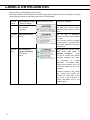
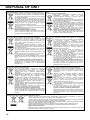
LABELS ON INCUBATOR
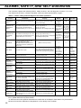
Warning Safety Labels Applied to the Incubator
Users are advised to avoid accidents by carefully reading the warnings and cautions contained on warning
stickers at key locations on the interior and exterior of the incubator.
Possible
Danger
Warning/Caution Type
Location of Danger
Warning/Caution Label Description of Danger
Burns Hot Surface
Cooling Unit &
Heat Cover
Avoid touching the cooling unit
and heat cover, which reaches
high temperatures and may cause
burns.
Personal
injury
Hazardous UV Light
Interior
The UV light is hazardous.
Never turn on the UV lamp without
the cover.
The UV lamp lights by pressing
the door switch. Do not press the
door switch because the UV light
is hazardous.
Personal
injury
Gas Poisoning or
Oxygen Deprivation
Environment
Interior
When using CO2 gas for control,
make sure that there is
adequate ventilation. Using
CO2 gas in a small room without
adequate ventilation may cause
gas poisoning or oxygen
deprivation. In addition, when
opening the Incubator doors, do
not directly inhale the air in the
chamber.
Excessive pressure may cause
gas supply lines inside the
Incubator to come loose, which
may result in gas poisoning or
oxygen deprivation due to the
escaping of gas.

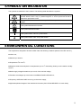
9
SYMBOLS ON INCUBATOR
The symbols are attached to the incubator. The following table describes the symbols.
This symbol is attached to covers that access high-voltage electrical components to
prevent electric shock. Only a qualified engineer or service personnel should be
allowed to open these covers.
This symbol indicates that caution is required. Refer to product documentation for
details.
This symbol indicates a hot surface.
This symbol indicates an earth.
This symbol means “ON” for a power switch.
This symbol means “OFF” for a power switch.
ENVIRONMENTAL CONDITIONS
This equipment is designed to be safe at least under the following conditions (based on the IEC 61010-1):
■ Indoor use;
■ Altitude up to 2000 m;
■ Temperature 5oC to 40oC;
■ Maximum relative humidity 80% for temperature up to 31oC decreasing linearly to 50% relative humidity
at 40oC;
■ Mains supply voltage fluctuations up to ±10% of the nominal voltage;
■ Transient overvoltages up to the levels of OVERVOLTAGE CATEGORY II;
■ Temporary OVERVOLTAGES occurring on the mains supply;
■ Applicable pollution degree of the intended environment (POLLUTION DEGREE 2 in most cases);

10
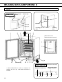
INCUBATOR COMPONENTS
Unit
1 2 3 Tray 4 5
6
7*
12
11 Electric key 10 9 8 18
* MCO-170AICUVDL or when an optional UV
System Set For Dry Heat MCO-170UVSD is
installed.
(When 12 is removed)
Sample air outlet cap
17 16 15* 14 13
19
Leveling
feet
Leveling
foot
Handles
Removable power
supply cord port
Lower right side
(When some inner
attachments are removed)
20
21
Access port
cover Silicon cap
Rear side

11
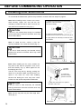
1. Outer door: The outer door is held to the frame with the magnetic seal. The door heater is installed in
the door panel. The door opening is reversible. Contact our sales representative or agent to change the
door hinge from left to right or vice versa.
2. Inner door: The inner door is made of tempered glass. However do not subject the glass to excessive
impacts.
3. Tray catches: Insert tray to fit the concave portion on chamber.
4. Fan cover: The fan cover serves as the inlet for circulating air. It is removable.
5. Duct: The duct for the path for circulating air. It is removable.
6. Fan (inside the duct): It can be sterilised in an autoclave.
7. UV lamp*: This UV lamp does not generate ozone. Never look directly at the UV light. Refer to page
75~79for using. For replacement, contact our sales representative or agent.
8. Humidifying pan cover: This cover prevents the UV light entering the chamber. Always use it. Using
without it may have a bad influence on the chamber temperature distribution and humidity recovery.
9. Humidifying pan: Fill the humidifying pan with sterile distilled water, and set the humidifying pan with
the inner side flush against the back. Install the humidifying pan in a longitudinal direction as its shorter
side is placed in the back.
10. Door switch: Detects the door opening/closing and stops the fan and electromagnetic valve for CO2
when the door is open. The UV lamp* is also deactivated by the door opening.
11. Key hole: This is the hole to unlock with unlock key while outer door is locked by electric lock.
12. Switch cover: Prevent the accident of gas tube disconnected or power off by the unexpected touch.
13. Power supply cord cover plate: This plate is to prevent the removable power supply cord being
come off.
14. Connecting port A for CO2 gas pipe: Refer to page 20 for gas cylinder connection. Ensure that the
secondary side pressure of the gas regulator is the specified value (refer to page 20 or 80).
Note: When the optional MCO-21GC gas auto changer is installed, both ports A and B are available. Refer
to page 80~83 for gas auto changer.
15. Glow starter*: The glow is started for the UV lamp.
16. Power switch: This is the main switch for the incubator (ON-“I”, OFF-“O”). It also functions as an
overcurrent breaker.
17. Sample air outlet: The sample air outlet also functions as an internal gas outlet. Normally, cover this
outlet with the sample air outlet cap.
18. Service port: It is possible to relocate the sample air outlet from 17 to here. Contact our sales
representative or agent.
19. USB port: Insert USB memory to export operation, alarm and dry heat sterilisation logs. Refer to page
46~58.
Note: It is impossible to use USB memory which is required password input.
20. Access port: Place the silicon caps on both outside and inside of the port when the port is not being
used.
21. Remote alarm terminals: This terminal informs the alarm to remote location by connecting to external
alarm unit. Refer to page 14.

12
INCUBATOR COMPONENTS
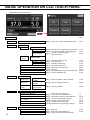
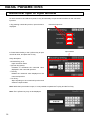
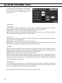
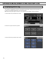
LCD touch panel
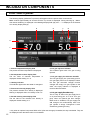
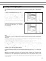
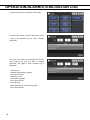
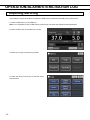
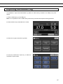
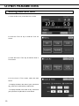
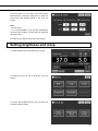
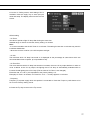
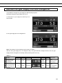
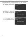
The following display (called the Top screen) will appear when the power switch is turned ON.
Note: It takes approximately 20 seconds until the Top screen is displayed. During warming-up, “Status:
Gas sensor initializing” is displayed in the Message display field (13), and “--.-” is displayed in the Present
CO2 density display field (4).
2 6 7 8
3
1
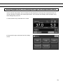
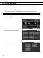
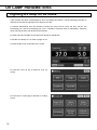
1. Present temperature display field
The present chamber temperature is displayed.
2. Set temperature value display field
The set value of chamber temperature is
displayed. Default setting: 37 oC.
3. Heating indicator
This indicator lights when the heater is energized.
4. Present CO2 density display field
The present chamber CO2 density is displayed.
Nothing is displayed when CO2 density is set 0 %.
5. Set CO2 density value display field
The set value of the chamber CO2 density is
displayed. Default setting: 0 %.
6. CO2 gas injection indicator
This indicator lights when CO2 gas is being
injected.
7. CO2 gas supply line indicator A and B*
The CO2 gas supply line (connecting port for
CO2 gas pipe) used now is displayed. When
the CO2 gas automatic changer function
changes the empty CO2 gas cylinder to the
other, the empty indicator is displayed in
reverse video and blinks.
8. CO2 gas supply line select key*
This is a key to select CO2 gas supply line A
or B (Connecting port A or B for CO2 gas
pipe). When an optional gas auto changer
MCO-21GC is installed, CO2 gas supply line
A/B changes over automatically when CO2
gas cylinder is empty. Changeover is also
workable by pressing this key.
* Only when an optional component MCO-21GC (Gas auto changer) is installed, this key is workable. They are
not displayed when the MCO-21GC is not installed.
5
4

13
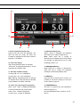
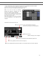
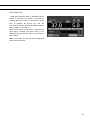
10 11 9 12
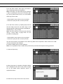
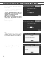
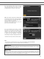
13
18 17 16 15
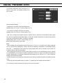
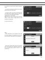
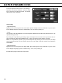
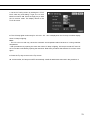
9. Present date/time display field
Present date and time are displayed. The
date and time are simply set when the
incubator is shipped from the factory. Refer to
page 60~61 for details.
10. Over heat display
High limit temperature alarm is activated:
“Over Heat” is displayed alternately in normal
characters and reverse video.
11. UV lamp condition display
UV lamp ON: “UV : On” is displayed.
UV lamp OFF: “UV : Off” is displayed.
Note: Nothing is displayed when an optional
UV System Set For Dry Heat MCO-170UVSD
is not installed to the MCO-170AICDL.
12. Outer door (opening/closing) display
Open: “Door : Open” is displayed alternately
in normal characters and reverse video.
Close: “Door : Closed” is displayed.
Locked: “Door : Locked” is displayed.
13. Message display field
Alarms, errors or messages are displayed
when fault occurs. Refer to page 88~91.
Note: When there are a number of
alarms/errors, the display shows the message.
For example, if 2 alarms/errors occur in total,
the display shows “1/2”.
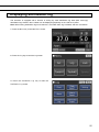
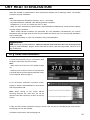
14. Message select key
When there are a number of alarm/errors,
press this key to change the displayed
message in the Message display field.
15. Menu key
Press this key to lead the Menu screen. It is
possible to set various setting on the Menu
screen. Refer to page 30.
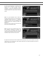
16. Sterilisation key
This key is to perform dry heat sterilisation.
Refer to page 63~67.
Dry heat sterilisation temp. and time: 180 oC -
60 min.
14

14
INCUBATOR COMPONENTS
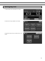
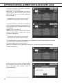
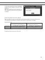
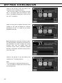
17. Unlock key
Press this key is to unlock the outer door when
it is auto-locked by electric lock. Refer to page
72. When the auto lock function is OFF, this
key is not displayed.
18. Buzzer key
Press this key to silence the buzzer. However,
when the ring back is ON, the buzzer will
sound again when the set time of ring back
passed and the alarm state still continues.
Refer to page 39~40 and 88~89.
Note: It is not possible to silence the buzzer
for the high limit temperature alarm.
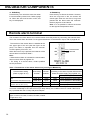
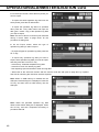
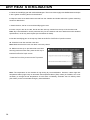
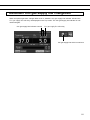
Remote alarm terminal
The incubator can inform alarms at a remote location from this product by connecting the external alarm
unit to the remote alarm terminals. For the type and behavior of remote alarm output, refer to page 88~91.
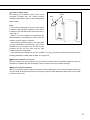
The terminal of the remote alarm is installed at the
rear upper right of the unit (See the figure on the
point). The alarm is outputted from this terminal.
Contact capacity is DC 30 V, 2 A.
When the Buzzer key is pressed, the behavior of the
remote alarm is showed in Table.1.
Note:
• When the door alarm is activated, the remote alarm
does not work. Refer to page 88~91.
• For wiring of a remote alarm, contact qualified
service personnel.
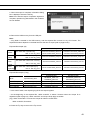
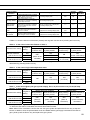
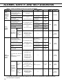
Table 1 The behavior of the remote alarm when pressing the Buzzer key
Remote Alarm setting
(Refer to page 39~41)
Connecting
terminal
Normal
condition
Abnormal condition
(Including in the cases of power failure and of
where the power supply plug is pulled out.)
When pressing the Buzzer key
ON:
Non-interlock with the Buzzer key
COM.-N.C. Close Open Open (Maintain in abnormality)*
COM.-N.O. Open Close Close (Maintain in abnormality)*
OFF:
Interlock with the Buzzer key
COM.-N.C. Close Open Close (Return to normal)
COM.-N.O. Open Close Open (Return to normal)
*In the case of Err01 (CO2 gas cylinder empty), Err11 and 12(both CO2 sensor error), the condition returns
to normal. Incidentally in the case of Err18 (UV lamp failure), the condition return to normal if the Buzzer
key is pressed after the UV lamp ON period elapses.
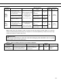
Remote alarm
terminal
Use a twisted sealed wire for the connection.
Type: UL 2343, UL 2448, UL 2464, UL 2552, UL2623.
Length:30 m max.

15
INSTALLATION
Installation site
For correct operation of the incubator, install it in a location with the following conditions.
WARNING
When using CO2 gas for control, make sure that there is an adequate ventilation. Using CO2 gas in a
small room without adequate ventilation may cause gas poisoning or oxygen deprivation. In addition, when
opening the incubator doors, do not directly inhale the air in the chamber.
Si l’appareil est utilisé dans un evdroit restreint, le niveau de la densite CO2 de l’air peut s’élever et peut
être nocif aux humains. Evitez d’aspirer l’air provenant de l’inérieur de l’appareil quand vous ouverz la
porte.
Normal air environment
Install the incubator in an environment with normal air.
Adequate ventilation
Leave at least 10 cm around the unit for ventilation. Poor ventilation will result in a reduction of the
performance and consequently the failure.
Do not expose to direct sunlight
Do not install the incubator in a location where it will be exposed to direct sunlight. If the incubator is
operated in direct sunlight, performance will be adversely affected.
Separate from heat sources
Do not install the incubator near significant heat sources, such as heaters, boilers, ovens, or autoclaves.
Heat will adversely affect the performance of the incubator.
Ambient temperature at least 5 C lower than set temperature
The control temperature of the incubator is at least 5 C higher than the ambient temperature. For example,
if the chamber is controlled at 37 C, the ambient temperature must be 32 C or less. Do not allow the
ambient temperature to become too high.
Strong and level floor
Select a site with a strong and level floor. If the floor is uneven or the installation is not level, the incubator
will be unstable and this may cause accident or injury. To avoid vibration and noise, always make sure that
the installation is stable. An unstable surface may result in vibration or noise.
WARNING
Install the incubator at a location that can support the weight. If the floor is not strong enough or if the
installation is insufficient, the incubator may fall over and cause injury.
Always make sure that the floor is strong, even, and level, and that the incubator will not tip over.
An insufficient installation may result in injury due to water leakage or the incubator falling over.
Separate from vibration products
Do not install the incubator near vibration products. Vibration may cause culture failure.

16
INSTALLATION
Low humidity
Select a site with a relative humidity of 80 %R.H. or lower. Using the incubator in high humidity may result
in current leakage or electric shock.
WARNING
Do not use the incubator outdoors. If the incubator is exposed to rain water, it may result in current
leakage or electric shock.
Never install the incubator in a moist location, such as near a sink or water line, or where it is likely
to be exposed to water. In addition, do not install it near water or steam pipes. Moisture can cause the
insulation to deteriorate, which may result in current leakage or electric shock.
No inflammable or corrosive gas
Never install the incubator in a location where it will be exposed to inflammable or corrosive gas. Doing so
may result in explosion or fire. In addition, insulation may deteriorate due to corrosion of protective casing,
resulting in current leakage or electric shock.
No falling objects
Do not install the incubator in a location where there is the possibility of objects falling from above. Doing
so may result in damage or accident.

17
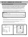
Installation
1. Remove the packing tape and clean up.
Remove all the tapes that are securing the doors and the inner attachments. Open the doors for ventilation.
If the outer panels are dirty, wet a cloth with a diluted neutral detergent and wipe them. (Undiluted
detergent can damage the plastic components. For the dilution, refer to the instruction of the detergent.)
Wipe off the residual detergent with a wet cloth and then wipe off any moisture.
Note: Remove the cable tie banding the power supply cord. Prolonged banding may cause the corrosion
of the cord coating.
WARNING
Do not leave the plastic wrapping bags within reach of children. If the bag is placed over a child’s
head, it can block the mouth and nose and cause suffocation.
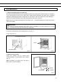
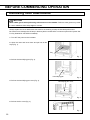
2. Set the humidifying pan and humidifying pan cover (Fig. 1).
3. Set 4 trays (Fig. 2).
4. Adjust the leveling feet.
Adjust the leveling feet by turning them
counterclockwise to horizontalise the incubator
(Fig. 3).
Note: Incubating on a leaning tray may have a
bad influence on the cultivation.
Fig. 1 Fig. 2
4 trays
Humidifying pan
Humidifying pan cover
Fig. 3
Leveling feet
Shorten
Lengthen

18
INSTALLATION
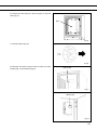
5. Ground the incubator.
Ground the incubator during installation to prevent electric shock in case the insulation is not sufficient. If
there is no ground wire at the location, consult with qualified service personnel.
When a ground must be installed
If a grounded 3-pole outlet is not available, then a ground must be installed. Consult with qualified service
personnel.
WARNING
To prevent electric shock, always ground the incubator. If grounding is not possible, then have a ground
installed by qualified personnel. If the incubator is not grounded, it may result in electric shock.
Never connect the ground wire to a gas pipe, water pipe, lightning rod, or telephone ground wire.
Doing so may cause electric shock.
Installing a ground fault circuit breaker
If using the incubator in the location with moisture or humidity cannot be avoided, then it is recommended
that a ground fault circuit breaker be installed in the power supply circuit (i.e., the power supply at the
incubator). Have the circuit breaker installed by qualified service personnel.
CAUTION
Do not climb on the incubator or place objects on top of it. Doing so may damage it or cause it to fall
over, resulting in injury.
Pagina se încarcă ...
Pagina se încarcă ...
Pagina se încarcă ...
Pagina se încarcă ...
Pagina se încarcă ...
Pagina se încarcă ...
Pagina se încarcă ...
Pagina se încarcă ...
Pagina se încarcă ...
Pagina se încarcă ...
Pagina se încarcă ...
Pagina se încarcă ...
Pagina se încarcă ...
Pagina se încarcă ...
Pagina se încarcă ...
Pagina se încarcă ...
Pagina se încarcă ...
Pagina se încarcă ...
Pagina se încarcă ...
Pagina se încarcă ...
Pagina se încarcă ...
Pagina se încarcă ...
Pagina se încarcă ...
Pagina se încarcă ...
Pagina se încarcă ...
Pagina se încarcă ...
Pagina se încarcă ...
Pagina se încarcă ...
Pagina se încarcă ...
Pagina se încarcă ...
Pagina se încarcă ...
Pagina se încarcă ...
Pagina se încarcă ...
Pagina se încarcă ...
Pagina se încarcă ...
Pagina se încarcă ...
Pagina se încarcă ...
Pagina se încarcă ...
Pagina se încarcă ...
Pagina se încarcă ...
Pagina se încarcă ...
Pagina se încarcă ...
Pagina se încarcă ...
Pagina se încarcă ...
Pagina se încarcă ...
Pagina se încarcă ...
Pagina se încarcă ...
Pagina se încarcă ...
Pagina se încarcă ...
Pagina se încarcă ...
Pagina se încarcă ...
Pagina se încarcă ...
Pagina se încarcă ...
Pagina se încarcă ...
Pagina se încarcă ...
Pagina se încarcă ...
Pagina se încarcă ...
Pagina se încarcă ...
Pagina se încarcă ...
Pagina se încarcă ...
Pagina se încarcă ...
Pagina se încarcă ...
Pagina se încarcă ...
Pagina se încarcă ...
Pagina se încarcă ...
Pagina se încarcă ...
Pagina se încarcă ...
Pagina se încarcă ...
Pagina se încarcă ...
Pagina se încarcă ...
Pagina se încarcă ...
Pagina se încarcă ...
Pagina se încarcă ...
Pagina se încarcă ...
Pagina se încarcă ...
Pagina se încarcă ...
Pagina se încarcă ...
Pagina se încarcă ...
Pagina se încarcă ...
Pagina se încarcă ...
Pagina se încarcă ...
Pagina se încarcă ...
Pagina se încarcă ...
Pagina se încarcă ...
Pagina se încarcă ...
Pagina se încarcă ...
-
 1
1
-
 2
2
-
 3
3
-
 4
4
-
 5
5
-
 6
6
-
 7
7
-
 8
8
-
 9
9
-
 10
10
-
 11
11
-
 12
12
-
 13
13
-
 14
14
-
 15
15
-
 16
16
-
 17
17
-
 18
18
-
 19
19
-
 20
20
-
 21
21
-
 22
22
-
 23
23
-
 24
24
-
 25
25
-
 26
26
-
 27
27
-
 28
28
-
 29
29
-
 30
30
-
 31
31
-
 32
32
-
 33
33
-
 34
34
-
 35
35
-
 36
36
-
 37
37
-
 38
38
-
 39
39
-
 40
40
-
 41
41
-
 42
42
-
 43
43
-
 44
44
-
 45
45
-
 46
46
-
 47
47
-
 48
48
-
 49
49
-
 50
50
-
 51
51
-
 52
52
-
 53
53
-
 54
54
-
 55
55
-
 56
56
-
 57
57
-
 58
58
-
 59
59
-
 60
60
-
 61
61
-
 62
62
-
 63
63
-
 64
64
-
 65
65
-
 66
66
-
 67
67
-
 68
68
-
 69
69
-
 70
70
-
 71
71
-
 72
72
-
 73
73
-
 74
74
-
 75
75
-
 76
76
-
 77
77
-
 78
78
-
 79
79
-
 80
80
-
 81
81
-
 82
82
-
 83
83
-
 84
84
-
 85
85
-
 86
86
-
 87
87
-
 88
88
-
 89
89
-
 90
90
-
 91
91
-
 92
92
-
 93
93
-
 94
94
-
 95
95
-
 96
96
-
 97
97
-
 98
98
-
 99
99
-
 100
100
-
 101
101
-
 102
102
-
 103
103
-
 104
104
-
 105
105
-
 106
106


Phcbi MCO-170AICDL Instrucțiuni de utilizare
- Tip
- Instrucțiuni de utilizare
- Acest manual este potrivit și pentru
în alte limbi
Lucrări conexe
-
Phcbi MPR-514R Instrucțiuni de utilizare
-
-
-
-
-
-
-
-
-
Alte documente
-
Dometic TwinBoost4000, TwinBoost4000E, TwinBoost6000, TwinBoost6000E Manual de utilizare
-
Dometic CH4000 Manual de utilizare
-
Medtronic Filterline Manual de utilizare
-
JBL PROFLORA Manual de utilizare
-
-
Samsung AC100RXADKG/EU Manual de utilizare
-
-
Samsung AC120MXADKH/EU Ghid de instalare
-
Samsung AC090HCADKH/EU Manualul utilizatorului
-
Samsung AC100KX4DKH/EU Manualul utilizatorului