


1
CONTENTS
INTRODUCTION ································································2
PRECAUTIONS FOR SAFE OPERATION ·······························3
ENVIRONMENTAL CONDITIONS ··········································7
REFRIGERATOR COMPONENTS
Refrigerator unit ·····························································8
Control panel components ·············································· 10
INSTALLATION SITE ························································ 11
INSTALLATION ································································ 12
START-UP OF UNIT ························································· 13
TEMPERATURE SETTING ················································· 14
KEY LOCK FUNCTION ······················································ 15
DEFROSTING OF FREEZER ·············································· 15
DEFROSTING ·································································· 16
ALARM TEMPERATURE SETTING ······································ 17
SETTING OF ALARM RESUME TIME ··································· 19
REMOTE ALARM TERMINAL ············································· 19
ALARMS AND SAFETY FUNCTIONS ··································· 20
ROUTINE MAINTENANCE
Cleaning ····································································· 21
Replacement of lamp ···················································· 22
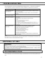
TROUBLESHOOTING ······················································· 23
DISPOSAL OF UNIT ························································· 23
Decontamination of unit ················································· 23
OPTIONAL COMPONENT
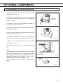
Temperature recorder ···················································· 28
Installation of MTR-0621LH ············································ 29
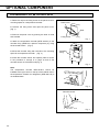
Installation of MTR-4015LH ············································ 30
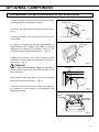
Installation of MTR-G3504A or MTR-G3504C ····················· 31
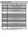
SPECIFICATIONS ···························································· 32
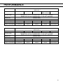
PERFORMANCE ······························································ 33
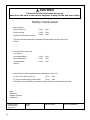
SAFETY CHECK SHEET ··················································· 34

2
INTRODUCTION
Read the operating instructions carefully before using the appliance and follow the instructions for
safety operation.
PHC Corporation never guarantees any safety if the appliance is used for any objects other than
intended use or used by any procedures other than those mentioned in the operating instructions.
Keep the operating instructions in an adequate place to refer to it as necessary.
The contents of the operating instructions will be subjected to change without notice due to the
improvement of performance or functions.
Contact our sales representative or agent if any page of the operating instructions is lost or page order
is incorrect.
Contact our sales representative or agent if any point in the operating instructions is unclear or if there
are any inaccuracies.
No part of the operating instructions may be reproduced in any form without the expressed written
permission of PHC Corporation.
IMPORTANT NOTICE
PHC Corporation guarantees this product under certain warranty conditions. However, please note that
PHC Corporation shall not be responsible for any loss or damage to the contents of the product.
<Intended Use>
This equipment is designed for storage of pharmaceuticals, samples and reagents.

3
PRECAUTIONS FOR SAFE OPERATION
It is imperative that the user complies with the operating instructions
as it contains important safety advice.
Items and procedures are described so that you can use this unit correctly and safely.
If the precautions advised are followed, this will prevent possible injury to the user and
any other person.
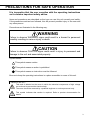
Precautions are illustrated in the following way:
WARNING
Failure to observe WARNING signs could result in a hazard to personnel
possibly resulting in serious injury or death.
CAUTION
Failure to observe CAUTION signs could result in injury to personnel and
damage to the unit and associated property.
Symbol shows;
This symbol means caution.
This symbol means an action is prohibited.
This symbol means an instruction must be followed.
Be sure to keep the operating instructions in a place accessible to users of this unit.
< Labels on the unit >
This mark is labeled on the cover in which the electrical components of high voltage
are enclosed to prevent the electric shock.
The cover should be removed by a qualified engineer or service personnel only.
This symbol indicates that caution is required. Refer to product documentation for
details.

4
PRECAUTIONS FOR SAFE OPERATION
Do not use the unit outdoors. Current leakage or electric shock may result if the unit is exposed to
rain water.
Only qualified engineers or service personnel should install the unit. The installation by
unqualified personnel may cause electric shock or fire.
Install the unit on a sturdy floor and take an adequate precaution to prevent the unit from
turning over. If the floor is not strong enough or the installation site is not adequate, this may result
in injury from the unit falling or tipping over.
Never install the unit in a humid place or a place where it is likely to be splashed by water.
Deterioration of the insulation may result which could cause current leakage or electric shock.
Never install the unit in a flammable or volatile location. This may cause explosion or fire.
Never install the unit where acid or corrosive gases are present as current leakage or electric
shock may result due to corrosion.
Always ground (earth) the unit to prevent electric shock. If the power supply outlet is not
grounded, it will be necessary to install a ground by qualified engineers.
Never ground the unit through a gas pipe, water main, telephone line or lightning rod. Such
grounding may cause electric shock in the case of an incomplete circuit.
Connect the unit to a power source as indicated on the rating label attached to the unit. Use
of any other voltage or frequency other than that on the rating label may cause fire or electric shock.
Never store volatile or flammable substances in this unit if the container cannot be sealed. These
may cause explosion or fire.
Do not insert metal objects such as a pin or a wire into any vent, gap or any outlet on the unit.
This may cause electric shock or injury by accidental contact with moving parts.
Use this unit in safe area when treating the poison, harmful or radiate articles. Improper use
may cause bad effect on your health or environment.
Turn off the power switch (if provided) and disconnect the power supply to the unit prior to
any repair or maintenance of the unit in order to prevent electric shock or injury.
Do not touch any electrical parts (such as power supply plug) or operate switches with a wet
hand. This may cause electric shock.
WARNING

5
PRECAUTIONS FOR SAFE OPERATION
Ensure you do not inhale or consume medication or aerosols from around the unit at the time of
maintenance. These may be harmful to your health.
Never splash water directly onto the unit as this may cause electric shock or short circuit.
Never put containers with liquid on the unit as this may cause electric shock or short circuit when
the liquid is spilled.
Never bind, process, or step on the power supply cord, or never damage or break the power
supply plug. A broken power supply cord or plug may cause fire or electric shock.
Do not use the power supply cord if its plug is loose. Such power supply cord may cause fire or
electric shock.
Never disassemble, repair, or modify the unit yourself. Any such work carried out by an
unauthorized person may result in fire, or electric shock or injury due to a malfunction.
Disconnect the power supply plug if there is something wrong with the unit. Continued
abnormal operation may cause electric shock or fire.
When removing the power supply plug from the power supply outlet, grip the power supply
plug, not the cord. Pulling the power supply cord may result in electric shock or fire by short circuit.
Disconnect the power supply plug before moving the unit. Take care not to damage the power
supply cord. A damaged power supply cord may cause electric shock or fire.
Disconnect the power supply plug when the unit is not used for long periods. Keeping the
connection may cause electric shock, current leakage, or fire due to the deterioration of insulation.
If the unit is to be stored unused in an unsupervised area for an extended period, ensure that
children do not have access and that doors cannot be closed completely.
The disposal of the unit should be accomplished by appropriate personnel. Remove doors to
prevent accidents such as suffocation.
Do not put the packing plastic bag within reach of children as suffocation may result.
Do not position this unit and the other unit so that it is difficult to operate the disconnection of
the power supply plug. Failure to disconnect the power supply plug may cause fire if there is
something wrong with the unit.
WARNING

6
PRECAUTIONS FOR SAFE OPERATION
This unit must be plugged into a dedicated circuit protected by branch circuit breaker.
Use a dedicated power source as indicated on the rating label attached to the unit. A
multiple-tap may cause fire resulting from abnormal heating.
Connect the power supply plug to the power source firmly after removing the dust on the plug.
A dusty power supply plug or improper insertion may cause a heat or ignition.
Never store corrosive substances such as acids or alkalis in the unit except in a sealed
container. These may be detrimental to health and may cause corrosion of internal components,
cooling circuit or electrical components.
Check the setting when starting up of operation after power failure or turning off of power
switch. The stored items may be damaged due to the change of setting.
Be careful not to tip over the unit during movement to prevent damage or injury.
Prepare a safety check sheet when you request any repair or maintenance for the safety of service
personnel.
CAUTION

7
ENVIRONMENTAL CONDITIONS
This equipment is designed to be safe at least under the following conditions (based on the IEC
61010-1):
Indoor use;
Altitude up to 2000 m;
Temperature 5 oC to 40 oC
Maximum relative humidity 80 % for temperature up to 31 oC decreasing linearly to 50 % relative
humidity at 40 oC;
Mains supply voltage fluctuations up to ±10 % of the nominal voltage;
Transient overvoltages up to the levels of OVERVOLTAGE CATEGORY II;
Temporary OVERVOLTAGES occurring on the mains supply;
Applicable pollution degree of the intended environment (POLLUTION DEGREE 2 in most cases);

8
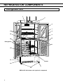
REFRIGERATOR COMPONENTS
Refrigerator unit
MPR-414F with drawer rack (optional component)
3
7
4
6
4
5
10
10
2 1
11
14
13
12
17
15
Freezer
Refrigerator
16
8
9

9
REFRIGERATOR COMPONENTS
1. Circulating fan: This is for cooling the refrigerator uniformly. Fan is installed inside the enclosure.
Do not insert anything into the enclosure. The air exhaust vent is located at the upper of the fan.
2. Air intake vent: Ensure this vent is never blocked. Failure to do so will result in unstable
temperature distribution in the refrigerator.
3. Control panel: The operation status is displayed on this panel. And the temperature setting is
available through this panel. Refer to page 10 for the details.
4. Mounting space for a temperature recorder: Space for a temperature recorder is available
separately. See page 28 for the mounting of the temperature recorder.
5. Lamp: This lamp lights up when the refrigerator door is open to illuminate the chamber.
6. Glass window: Water can sometimes condense on the glass in areas of high humidity. Wipe off
the condensation with a dry soft cloth. (MPR-414FS has no glass window.)
7. Magnetic door gasket: This prevents the cool air from escaping. Always keep clean.
8. Movable center pillar: The pillar contact the door gasket firmly when the door is closed and
functions as a block between the chamber and outer air. When the door is opened, the pillar angle is
changed by 90 degree. Take care not to change the pillar angle.
9. Protective sheet: The stored material may be frozen if it is put on the chamber bottom directly.
Always put the sheet in the refrigerator compartment (upper and lower left chamber).
10. Lock: Turn a key clockwise through 180 degree to lock the door. The right side lock is for the right
upper and lower doors and left side lock is for the left upper and lower doors.
11. Access port (rear): This port allows cables to be passed into the cabinet.
12. Leveling foot: Use these bolts to adjust the height and level the unit for installation.
13. Remote alarm terminal: This is used to alarm the abnormality to the remote location. See page
19 for the details.
14. Power switch (also functions as a circuit breaker): The power switch also used as a circuit
breaker. Normally put a cover on the switch. The round button under the power switch is a leakage
test button. The operation check of the circuit breaker can be performed by pressing this button. But
note the power supply to the unit is disconnected when this button is pressed.
15. Drawer rack: Drawer rack is available as an optional component (MPR-41R).
16. Shelf (at the opening between upper and lower chamber): Ensure this surface is never blocked
by the stored items so that the cool air can be circulated into the lower chamber.
17. Cool air exhaust vent: Ensure this vent is never blocked. Note the items exposed to the direct air
flow can be frozen.

10
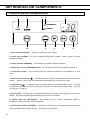
REFRIGERATOR COMPONENTS
Control panel components
1. Door check lamp (DOOR): This lamp is lit when the door is open.
2. Alarm lamp (ALARM): This lamp is flashed during alarm condition. Refer to page 17 “Alarm
temperature setting”.
3. Freezer indicator (FREEZER): This indicator is lit when the freezer is selected.
4. Refrigerator indicator (REFRIGERATOR): This indicator is lit when the refrigerator is selected.
5. Temperature display: This indicator shows the chamber temperature, set temperature, or error
code.
6. Numerical value shift key ( ): Pressing this key in the setting mode causes the numerical value to
change. “ON-OFF” of key lock can be selected by pressing this key in the key lock mode.
7. Digit shift key ( ): Pressing this key in set mode causes the changeable digits to move. Key lock
is activated by pressing this key for more than 5 seconds in the temperature display mode. See “Key
lock function” on page 15.
8. Set key (SET): Pressing this key activates temperature set mode and the digit which can be set is
flashed. By pressing the key again after setting, the set value is accepted.
9. Display select key (REF./FREEZ.): By pressing this key, chamber temperature display of
refrigerator or freezer and each setting is selected.
10. Alarm buzzer stop key (BUZZER): Press this key to silence the alarm buzzer in the event that the
alarm operates and alarm buzzer sounds. See page 20 for the details.
REFRIGERATOR
FREEZER
DOOR
REF.
FREEZ.
5
10 9 8 7 6
4 3 1 2

11
INSTALLATION SITE
To operate this unit properly and to obtain maximum performance, install the unit in a location with the
following conditions:
A location not subjected to direct sunlight
Do not install the unit under direct sunlight. Installation in a location subjected to direct sunlight cannot
obtain the intended performance.
A location with adequate ventilation
Leave at least 10 cm around the unit for ventilation. Poor ventilation will result in a reduction of the
performance and consequently the failure.
A location away from heat generating sources
Avoid installing the unit near heat-emitting appliances such as a heater or a boiler etc. Heat can
decrease the intended performance of the unit.
A location with little temperature change
Install the unit under stable ambient temperature. The allowable ambient temperature is between -5 oC
and +35 oC.
A location with a sturdy and level floor
Always install the unit on a sturdy and level floor. The uneven floor or tilted installation may cause
failure or injury. Install the unit in stable condition to avoid the vibration or noise. Unstable condition
may cause vibration or noise.
WARNING
Install the unit on a sturdy floor. If the floor is not strong enough or the installation site is not
adequate, this may result in injury from the unit falling or tipping over.
Select a level and sturdy floor for installation. This precaution will prevent the unit from tipping.
Improper installation may result in water spillage or injury from the unit tipping over.
A location not prone to high humidity
Install the unit in the ambient of 80 % R.H. or less humidity. Installation under high humidity may cause
current leakage or electric shock.
WARNING
Do not use the unit outdoors. Current leakage or electric shock may result if the unit is exposed to
rain water.
Never install the unit in a humid place or a place where it is likely to be splashed by water.
Deterioration of the insulation may result which could cause current leakage or electric shock.
CAUTION
The unit starts defrosting frequently due to excessive frost on the evaporator if it is installed in high
temperature and high humidity location. The chamber temperature goes up to approximately 10oC
temporarily during defrosting.
A location without flammable or corrosive gas
Never install the unit in a flammable or volatile location. This may cause explosion or fire or may result
in the current leakage or electric shock by the corrosion of the electrical components.
A location without the possibility of anything fall
Avoid installing the unit in the location where anything can fall down onto the unit. This may cause the
breakdown or failure of the unit.

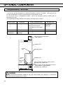
12
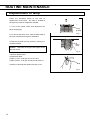
INSTALLATION
1. Remove the packaging materials and tapes
Remove all transportation packaging materials and
tapes. Open the doors and ventilate the unit. If the
outside panels are dirty, clean them with a diluted
neutral dishwashing detergent. (Undiluted detergent
can damage the plastic components. For the dilution,
refer to the instruction of the detergent.) After the
cleaning with the diluted detergent, always wipe it off
with a wet cloth. Then wipe off the panels with a dry
cloth.
Note:
Remove the cable tie banding the power supply cord.
Prolonged banding may cause the corrosion of the cord
coating.
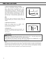
2. Adjusting the leveling foot
Extend the leveling feet by rotating them
counterclockwise to contact them to the floor.
Ensure the unit is level. (Fig.1)
3. Fixing the unit
Two fixtures are attached to the rear of the frame. Fix
the frame to the wall with these fixtures and rope or
chain. (Fig.2)
4. Ground (earth)
WARNING
Use a power supply outlet with ground (earth) to prevent electric shock. If the power supply outlet is
not grounded, it is necessary to install a ground by qualified engineers.
Never ground the unit through a gas pipe, water main, telephone line or lightning rod. Such
grounding may cause electric shock in the case of an incomplete circuit.
Note:
If an instrument requiring a power source is to be placed inside the cabinet, the cable can be lead through
the access port on the back side of the cabinet. After using of the port, a rubber cap and insulation
should be replaced to seal the access port. Failure to do this can affect the temperature uniformity
inside the cabinet and lead to condensation on the outside of the access port.
Leveling foot
Fixture
Fig.1
Fig.2

13
START-UP OF UNIT
The following procedures should be adhered to for initial start-up and continuous operation.
1. Connect the unit to dedicated power supply and turn on the power switch. Do not put any product in
the unit at this time.
Note:
If the unit is unplugged or the power to the unit is interrupted, do not restart the unit for at least 5 minutes.
This protects the compressor.
2. On start-up, the alarm buzzer sometimes operates. In this case, stop the alarm buzzer by pressing
the alarm buzzer stop key (BUZZER).
3. Set the desired temperature.
4. Confirm that the chamber temperature is at the desired temperature.
5. When you are satisfied that the unit is working correctly, begin slowly placing product into the chamber
to minimize the temperature rise.
Note:
Fix the shelves securely. Place items on the shelves and leave a space between the walls of the
cabinet and the contents to allow air circulation. Do not place items on the floor of the chamber.
CAUTION
This inner cabinet is refrigerated by the forced circulation of cooled air inside the chamber. Ensure that
the intake and exhaust vents are not blocked. Adequate space should be provided between the items
inside the unit to allow air circulation. Too much stock will result in temperature of about -2 oC around
the exhaust vent when the set temperature is 2 oC. It is recommended to set the temperature to 4 oC or
5 oC when a large quantity of articles that should not be frozen are stored.
The heat discharge pipe is attached inside of the rear frame. The rear frame is sometimes hot at the
start-up of the operation. But this does not mean malfunction.

14
TEMPERATURE SETTING
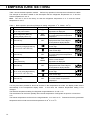
Table 1 shows the basic operation method. Perform key operation in the sequence indicated in the table.
The example in the table is based on the assumption that the refrigerator temperature is 4 oC and the
freezer temperature is -25 oC.
Note: The unit is set at the factory so that the refrigerator temperature is 5 oC and the freezer
temperature is -20 oC.
Table 1 Basic operation procedure (Example of setting: refrigerator; 4 oC, freezer; -25 oC)
Operation Key operated Indication after operation
1 Connect to the power source and
turn on the power switch. ----- The current refrigerator or freezer
temperature is displayed.
2 Select refrigerator (REF.) by
pressing display select key.
REF.
FREEZ.
The refrigerator indicator lights and
the current refrigerator temperature
is displayed.
3 Press set key. SET
The current set temperature is
displayed and the second digit of
the temperature display flashes.
4 Set to 004 by using digit shift key
and numerical value shift key.
Pressing the key leads the flash of
the first digit.
Pressing the key shifts up the figure
of the current digit.
5 Press set key. SET
The value is stored in memory and
the current refrigerator temperature
is displayed.
6
Select freezer (FREEZ.) by
pressing
display select key.
REF.
FREEZ.
The freezer indicator lights
and the current freezer
temperature is displayed.
7 Press set key. SET
The current set temperature is
displayed and the second digit of
the temperature display flashes.
8 Set to -25 by using digit shift key
and numerical value shift key.
Pressing the key leads the flash of
the first digit.
Pressing the key shifts up the figure
of the current digit.
9 Press set key. SET
The value is stored in memory and
the current freezer temperature
is displayed.
Note:
If no key has been pressed for about 90 seconds in the temperature set mode, the display mode returns
automatically to the temperature display mode. In this case, the chamber temperature setting is not
changed.
The effective temperature setting for refrigerator ranges between 2 oC and 14 oC.
The stored items can be frozen partially when the set temperature of refrigerator is equal to or lower than
3 oC.
The freezer temperature can be set in the range between -15 oC and -35 oC. Remember that the guaranteed
temperature with no load at an ambient temperature of 30 oC is -30 oC.

15
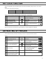
KEY LOCK FUNCTION
This unit incorporates a key lock feature which can inhibit the tampering using the keys on the control
panel.
The key lock is set to OFF at the factory.
Display Mode Function
L 0 Key lock OFF Temperature change enabled
L 1 Key lock ON Temperature change disabled
Table 2 Key lock setup procedure (Example: Key lock OFF → Key lock ON)
Operation Key operated Indication after operation
The current refrigerator or freezer
temperature is displayed.
1 Press and hold the digit shift
key for about 5 seconds.
The first digit of the temperature
display blinks.
2 Set the first digit to 1 with
the numerical value shift key.
Pressing the key shifts up the figure
of the digit.
3 Press the set key. SET
Key lock is set to ON and the current
refrigerator or freezer temperature is
displayed.
Note:
Key lock can be set any time when the current refrigerator or freezer temperature is displayed.
DEFROSTING OF FREEZER
Table 3 below shows the procedure for defrosting of freezer or stopping the freezer operation.
Table 3
Operation Key operated Indication after operation
1 Select freezer (FREEZ.) by
pressing display select key.
REF.
FREEZ.
The current freezer temperature
is displayed.
2 Press the set key. SET
The current set value is displayed
and the second digit of the tempera-
ture display flashes.
3 Set to -00 by using digit shift key
and numerical value shift key.
Pressing the key leads blink of the
first digit of the temperature display.
Pressing the key shifts up the figure
of the current digit.
4 Press the set key. SET
The value is stored in memory and
the current freezer temperature and
dF are displayed alternately.
(starting of defrosting)
5 Check the defrosting is finished.
6
Set the freezer temperature by the
procedure 6 through 9 in Table 1
and start the freezer operation.

16
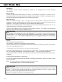
DEFROSTING
Refrigerator
The following 2 kinds of defrost methods are adopted for the refrigerator, which control defrosting
automatically.
Cycle defrost
To keep the temperature stable inside the chamber, the refrigeration compressor is cycled on and off.
During “off” periods any frost which has accumulated on the evaporator is melted by energizing a heater.
This will not have any discernible effect on the chamber temperature.
Forced defrost
When the ambient humidity is high, or a large amount of damp product is being stored inside the
refrigerator, there is a possibility that cycle defrost may not be enough to remove all of the frost on the
evaporator. In this case, a forced defrost cycle is initiated by the defrost sensor.
When the unit is operating under a forced defrost cycle, the current chamber temperature and “dF” are
displayed alternately on the digital temperature display.
Once the forced defrost cycle is complete, normal operation resumes. The chamber air temperature
rises up to about 10 oC during the forced defrost cycle.
CAUTION
The unit may collect excessive frost on the evaporator if it is installed in high temperature and high
humidity location. For example, the unit starts to defrost once a week with 2 oC setting in the ambient of
35 oC and 80 % R.H. The chamber temperature goes up to approximately 10 oC temporarily
during defrosting.
Freezer
Natural defrost by stopping operation.
The defrosting is performed by stopping the freezer operation.
When the frost is built-up on the freezer wall, defrost the freezer by the following procedure as the freezer
has no automatic defrosting function.
1. Temporarily move all the contents of the freezer to another freezer.
2. Set the freezer temperature to -00 and press the set key (SET). The current chamber temperature
and “dF” are displayed alternately on the temperature display. This is the starting of defrosting.
3. When the frost on the wall has been eliminated, remove the water and wipe the inside of the freezer
completely.
4. Set the freezer temperature to desired one.
5. Once the chamber temperature has reached to the desired temperature, place the original contents
back in the freezer.
Note: The freezer does not automatically reset to normal operation.
No temperature alarm is occurred during defrosting.
CAUTION
The cooling pipe is routed in the rear of the freezer. Never use a knife or a screw driver, etc. to remove
the frost. They may cause damage of chamber wall or improper operation of the unit. And do not drop
any heavy items or sharp edge materials onto the freezer floor.
Under such condition, the freezer is not cooled down at all.

17
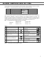
ALARM TEMPERATURE SETTING
The high temperature and low temperature at which the alarm will be activated are effective for freezer
and refrigerator. The following shows the outline of the alarm temperature setting.
Display Mode Application Settable range
F01 High temp. alarm setting Refrigerator +2 oC to +14 oC
F02 Low temp. alarm setting -2 oC to -14 oC
F03 High temp. alarm setting Freezer +5 oC to +15 oC
F04 Low temp. alarm setting -5 oC to -15 oC
Table 4 shows the basic operation for high temperature alarm setting and table 5 shows low temperature
alarm setting for refrigerator. Perform key operation in the sequence indicated in the table. The
example in the table is based on the assumption that the high temperature alarm is activated when the
chamber temperature deviates from set temperature by more than +3 oC and low temperature alarm is
activated when the chamber temperature deviates from set temperature by more than -3 oC.
Note: The temperature alarm setting at the factory is as follows:
High temp. alarm Low temp. alarm
Refrigerator Set temp. +5 oC Set temp. -5 oC
Freezer Set temp. +10
oC Set temp. -10 oC
Table 4
Operation Key operated Indication after operation
1
----- The current refrigerator temperature
is displayed.
2 Press and hold the numerical value
shift key for about 5 seconds.
The first digit of the temperature
display blinks.
3 Set the first digit to 1 with the
numerical value shift key. (Note 1)
Pressing the key shifts up the figure
of the current digit.
4 Press the set key. SET
The current set value is displayed
and the first digit of the temperature
display flashes.
5 Set to 003 by using digit shift key
and numerical value shift key.
Pressing the key leads the change of flashed
digit.
Pressing the key shifts up the figure
of the current digit.
6 Press the set key. SET
The value is stored in memory and
the current refrigerator temperature
is displayed.
Note 1: For the freezer, set the first digit to 3 (F03).

18
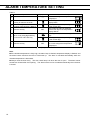
ALARM TEMPERATURE SETTING
Table 5
Operation Key operated Indication after operation
1
----- The current refrigerator temperature
is displayed.
2 Press and hold the numerical value
shift key for about 5 seconds.
The first digit of the temperature
display blinks.
3 Set the first digit to 2 with the
numerical value shift key. (Note 2) Pressing the key shifts up the figure
of the current digit.
4 Press the set key. SET
The current set value is displayed
and the first digit of the temperature
display flashes.
5 Set to -03 by using digit shift key
and numerical value shift key.
Pressing the key leads the change of flashed
digit.
Pressing the key shifts up the figure
of the current digit.
6 Press the set key. SET
The value is stored in memory and
the current refrigerator temperature
is displayed.
Note 2: For the freezer, set the first digit to 4 (F04).
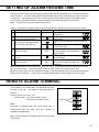
Note:
If the ambient temperature is fairly high, the alarm lamp is flashed, temperature display is flashed, and
the alarm buzzer sounds at the time of initial start up. The alarm is canceled automatically when the
chamber temperature is decreased.
Always close the door firmly. The door check lamp is lit when the door is open. The alarm buzzer
sounds two minutes after door opening. The alarm buzzer can be canceled automatically when the door
is closed.
Pagina se încarcă...
Pagina se încarcă...
Pagina se încarcă...
Pagina se încarcă...
Pagina se încarcă...
Pagina se încarcă...
Pagina se încarcă...
Pagina se încarcă...
Pagina se încarcă...
Pagina se încarcă...
Pagina se încarcă...
Pagina se încarcă...
Pagina se încarcă...
Pagina se încarcă...
Pagina se încarcă...
Pagina se încarcă...
Pagina se încarcă...
Pagina se încarcă...
Pagina se încarcă...
Pagina se încarcă...
-
 1
1
-
 2
2
-
 3
3
-
 4
4
-
 5
5
-
 6
6
-
 7
7
-
 8
8
-
 9
9
-
 10
10
-
 11
11
-
 12
12
-
 13
13
-
 14
14
-
 15
15
-
 16
16
-
 17
17
-
 18
18
-
 19
19
-
 20
20
-
 21
21
-
 22
22
-
 23
23
-
 24
24
-
 25
25
-
 26
26
-
 27
27
-
 28
28
-
 29
29
-
 30
30
-
 31
31
-
 32
32
-
 33
33
-
 34
34
-
 35
35
-
 36
36
-
 37
37
-
 38
38
-
 39
39
-
 40
40


Phcbi MPR-414F Instrucțiuni de utilizare
- Tip
- Instrucțiuni de utilizare
- Acest manual este potrivit și pentru
în alte limbi
- English: Phcbi MPR-414F Operating instructions
- eesti: Phcbi MPR-414F Kasutusjuhend
- italiano: Phcbi MPR-414F Istruzioni per l'uso
Lucrări înrudite
-
Phcbi MPR-1014 Instrucțiuni de utilizare
-
-
-
-
-
-
-
-
-
Alte documente
-
Electrolux ERA40633W Manual de utilizare
-
-
LG GC-P227STFA Manual de utilizare
-
Tesla RC3400FHX1 Manual de utilizare
-
Electrolux EN3881AOW Manual de utilizare
-
-
Heinner HFF-N240NFF+ Manualul proprietarului
-
Samsung RT59ZBTS Manual de utilizare