Parkside PMTS 210 A1 Operating And Safety Instructions Manual
- Categorie
- Unelte electrice
- Tip
- Operating And Safety Instructions Manual

IAN 322850_1901
CHAT
MOBILE TISCHKREISSÄGE
Bedienungs- und Sicherheitshinweise
Originalbetriebsanleitung
DE
FERĂSTRĂU CIRCULAR CU MASĂ, MOBIL
Instrucţiuni de utilizare şi de siguranţă
Traducerea instrucţiunilor de utilizare originale
RO
МОБИЛЕН НАСТОЛЕН ЦИРКУЛЯР
Инструкции за обслужване и безопасност
Превод на оригиналното ръководство за експлоатация
BG
PORTABLE TABLE SAW PMTS 210 A1
CY
PORTABLE TABLE SAW
Operating and Safety Instructions
Translation of Original Operating Manual
GB
MOBILNA STONA KRUŽNA TESTERA
Napomene za rukovanje i sigurnosne napomene
Originalno uputstvo za upotrebu
RS
BGRORS

GB / CY Operating and Safety Instructions Page 01
RS Napomene za rukovanje i sigurnosne napomene Strana 16
RO Instrucţiuni de utilizare şi de siguranţă Pagina 32
BG Инструкции за обслужване и безопасност страница 49
DE / AT / CH Bedienungs- und Sicherheitshinweise Seite 67
Before reading, unfold the page containing the illustrations and familiarise yourself with all functions of the device.
GB CY
Преди да прочетете отворете страницата с фигурите и след това се запознайте с всички функции на уреда.
BG
Klappen Sie vor dem Lesen die Seite mit den Abbildungen aus und machen Sie sich anschließend mit allen Funktionen des Gerätes vertraut.
DE AT CH
Pre nego što počnete sa čitanjem preklopite stranicu sa slikama, i upoznajte se sa svim funkcijama uređaja.
RS
Înainte de a citi instrucţiunile, priviţi imaginile şi familiarizaţi-vă cu toate funcţiile aparatului.
RO

4
1
3
5
2 5 741
8
14
13
12
18
911 10
3 6
2
7
2
16
17
19
15
15a
16a
4
14
20
21
26
29
28
22
23
24
25
27
30

10
66 7
988
1411
4a
12 1413
24
32
34
2021
33
25
23
4
35 20
36
3
6
3
31
max. 5mm

16
18
14
19
20
15
17
21
45°
8
17
16a
37
9
16
17
16
17
18
19
40
39
16a
38
38
16a
17

22
24
23
41
25
42
43
43
42
44
44

1GB/CY
Table of contents: Page:
1. Introduction ..........................................................................................................................................................................................................3
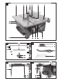
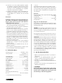
2. Device description (fig. 1-18, 24) ......................................................................................................................................................................3
3. Scope of delivery ................................................................................................................................................................................................4
4. Intended use ........................................................................................................................................................................................................ 4
5. Safety information ............................................................................................................................................................................................... 4
6. Technical data ..................................................................................................................................................................................................... 8
7. Before starting the equipment ............................................................................................................................................................................9
8. Assembling the equipment ..................................................................................................................................................................................9
9. Handling the equipment ...................................................................................................................................................................................10
10. Using the equipment .........................................................................................................................................................................................11
11. Transporting the equipment (fig. 24) ...............................................................................................................................................................12
12. Maintaining the equipment ..............................................................................................................................................................................12
13. Storing the equipment .......................................................................................................................................................................................12
14. Electrical connection .........................................................................................................................................................................................12
15. Disposal and recycling .....................................................................................................................................................................................13
16. Troubleshooting .................................................................................................................................................................................................14
17. Warranty certificate ..........................................................................................................................................................................................15
18. Declaration of conformity .................................................................................................................................................................................84

2 GB/CY
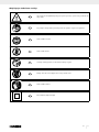
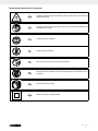
Explanation of the symbols on the equipment
GB CY
WARNING: Failure to comply with may lead to danger to life, risk of injury or damage to
the tool.
GB CY
Read instruction manual and safety instructions before starting up and pay attention to them.
GB CY
Wear safety goggles.
GB CY
Wear ear-muffs.
GB CY
Wear a dust mask.
GB CY
IMPORTANT: Risk of injury! Never reach into the running saw blade.
GB CY
Wear work gloves.
GB CY
Protection class II (double shielded)

3GB/CY
1. Introduction
Manufacturer:
scheppach
Fabrikation von Holzbearbeitungsmaschinen GmbH
Günzburger Straße 69
D-89335 Ichenhausen
Dear customer,
We hope your new tool brings you much enjoyment and suc-
cess.
Note:
According to the applicable product liability laws, the manu-
facturer of the device does not assume liability for damages
to the product or damages caused by the product that occurs
due to:
• Improper handling
• Non-compliance of the operating instructions
• Repairs by third parties, by not authorized service techni-
cians
• Installation and replacement of non-original spare parts
• Application other than specified
• A breakdown of the electrical system that occurs due to the
non-compliance of the electric regulations and VDE regula-
tions 0100, DIN 57113 / VDE0113
Please observe the following:
Read through the complete text in the operating instructions be-
fore installing and commissioning the device.
The operating instructions are intended to help the user to be-
come familiar with the machine and take advantage of its ap-
plication possibilities in accordance with the recommendations.
The operating instructions contain important information on
how to operate the machine safely, professionally and econom-
ically, how to avoid danger, costly repairs, reduce downtimes
and how to increase reliability and service life of the machine.
In addition to the safety regulations in the operating instruc-
tions, you have to meet the applicable regulations that apply
for the operation of the machine in your country.
Keep the operating instructions package with the machine at
all times and store it in a plastic cover to protect it from dirt and
moisture. Read the instruction manual each time before operat-
ing the machine and carefully follow its information.
The machine can only be operated by persons who were in-
structed concerning the operation of the machine and who are
informed about the associated dangers. The minimum age re-
quirement must be complied with.
In addition to the safety instructions contained in this operating
manual and the specific regulations of your country, the techni-
cal rules generally accepted for the operation of machines of
the same type must be observed.
We accept no liability for damage or accidents which arise
due to non-observance of these instructions and the safety in-
formation.
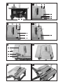
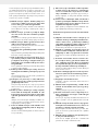
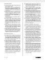
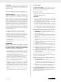
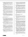
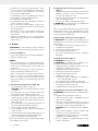
2. Device description (fig. 1-18, 24)
1. Saw table
2. Transverse stop
3. Riving knife
4. Saw blade guard
4a. Screw (saw blade guard)
5. Saw blade
6. Table inlay
7. Parallel stop, complete
8. Hand wheel
9. Locking handle
10. Overload switch
11. On/off switch
12. Rubber foot
13. Tool hook
14. Push stick
15. Locking knob
15a. Clamping plate
16. Holder
16a. Screw (parallel stop)
17. Stop rail
18. Knurled screw (transverse stop)
19. Turning handle
20. Ring spanner, 7/8 mm
21. Ring spanner, 19/10 mm
22. Table width extension
23. Guide tube
24. End piece
25. Screw (end piece)
26. Knurled screw (table width extension)
27. Guide bushing
28. Height adjustment screw
29. Lock nut
30. Support foot
31. Hole (riving knife)
32. Screw (table inlay)
33. Fixing screw (riving knife)
34. Screw (saw blade cover)
35. Saw blade cover
36. Suction port
37. Groove (stop rail)
38. Scale
39. Groove (stop rail)
40. Groove (saw table)
41. Mains cable
42. Bracket for workbench mounting
43. Screw (self-tapping)
44. Washers

4 GB/CY
3. Scope of delivery
• Saw blade guard
• Push stick
• Parallel stop
• Transverse stop
• Table width extension
• End pieces and screws for table width extension
• Assembly material
• Ring spanner, 19/10 mm
• Ring spanner, 7/8 mm
• Operating manual
4. Intended use
The circular table saw is used for the longitudinal and trans-
verse cutting (only with the transverse stop) of all types of
timbers and plastic, in accordance with the machine size. It is
not permitted to cut any type of round timber.
The equipment is allowed to be used only for its prescribed
purpose. Any other use is deemed to be a case of misuse.
The user/operator and not the manufacturer will be liable for
any damage or injuries of any kind resulting from such misuse.
The machine is to be operated only with suitable saw blades.
(HM or CV saw blades). The use of any type of HSS saw
blades and cutting discs is prohibited.
An element of the intended use is also the observance of the
safety instructions, as well as the assembly instructions and op-
erating information in the operating manual.
Persons who operate and maintain the machine must be fa-
miliar with the manual and must be informed about potential
dangers.
In addition, the applicable accident prevention regulations
must be strictly observed.
Other general occupational health and safety-related rules and
regulations must be observed.
m IMPORTANT
When using the equipment, a few safety precautions must
be observed to avoid injuries and damage. Please read the
complete operating instructions and safety regulations with
due care. Keep this manual in a safe place, so that the infor-
mation is available at all times. If you give the equipment to
any other person, hand over these operating instructions and
safety regulations as well. We cannot accept any liability for
damage or accidents which arise due to a failure to follow
these instructions and the safety instructions.
The manufacturer shall not be liable for any changes made to
the machine nor for any damage resulting from such changes.
Despite use as intended, specific risk factors cannot be entirely
eliminated. Due to the design and layout of the machine, the
following risks remain:
• Contact with the saw blade in the exposed sawing area
• Reaching into the running saw blade (cutting injury)
• Kick-back of workpieces and workpiece parts
• Saw blade breakage
• Ejection of faulty carbide parts of the saw blade
• Hearing damage when the necessary hearing protection is
not used
• Harmful emissions of wood dusts during use in enclosed ar-
eas
Please note that our equipment has not been designed for use
in commercial, trade or industrial applications. Our warranty
will be voided if the equipment is used in commercial, trade
or industrial businesses or for equivalent purposes.
5. Safety information
General power tool safety warnings
m WARNING: Read all safety warnings, instruc-
tions, illustrations and technical data provided
with this power tool. Failure to follow the warnings and in-
structions may result in electric shock, fire and/or serious injury.
Save all warnings and instructions for future refer-
ence.
The term “power tool” in the warnings refers to your mains-
operated (corded) power tool or battery-operated (cordless)
power tool.
1) Work area safety
a) Keep work area clean and well lit. Cluttered or
dark areas invite accidents.
b) Do not operate power tools in explosive atmos-
pheres, such as in the presence of flammable
liquids, gases or dust. Power tools create sparks
which may ignite the dust or fumes.
c) Keep children and bystanders away while op-
erating a power tool. Distractions can cause you to
lose control.
2) Electrical safety
a) Power tool plugs must match the outlet. Never
modify the plug in any way. Do not use any
adapter plugs with earthed (grounded) power
tools. Unmodified plugs and matching outlets will reduce
risk of electric shock.
b) Avoid body contact with earthed or grounded
surfaces, such as pipes, radiators, ranges and
refrigerators. There is an increased risk of electric
shock if your body is earthed or grounded.
c) Do not expose power tools to rain or wet condi-
tions. Water entering a power tool will increase the risk
of electric shock.
d) Do not abuse the cord. Never use the cord for
carrying, pulling or unplugging the power tool.
Keep cord away from heat, oil, sharp edges or
moving parts. Damaged or entangled cords increase
the risk of electric shock.
e) When operating a power tool outdoors, use an
extension cord suitable for outdoor use. Use of
a cord suitable for outdoor use reduces the risk of electric
shock.

5GB/CY
f) If operating a power tool in a damp location
is unavoidable, use a residual current device
(RCD) protected supply. Use of an RCD reduces the
risk of electric shock.
3) Personal safety
a) Stay alert, watch what you are doing and use
common sense when operating a power tool.
Do not use a power tool while you are tired or
under the influence of drugs, alcohol or medica-
tion. A moment of inattention while operating power tools
may result in serious personal injury.
b) Use personal protective equipment. Always
wear eye protection. Protective equipment such as
a dust mask, non-skid safety shoes, hard hat or hearing
protection used for appropriate conditions will reduce per-
sonal injuries.
c) Prevent unintentional starting. Ensure the
switch is in the off-position before connecting to
power source and/or battery pack, picking up
or carrying the tool. Carrying power tools with your
finger on the switch or energising power tools that have the
switch on invites accidents.
d) Remove any adjusting key or wrench before
turning the power tool on. A wrench or a key left
attached to a rotating part of the power tool may result in
personal injury.
e) Do not overreach. Keep proper footing and
balance at all times. This enables better control of the
power tool in unexpected situations.
f) Dress properly. Do not wear loose clothing or
jewellery. Keep your hair and clothing away
from moving parts. Loose clothes, jewellery or long
hair can be caught in moving parts.
g) If devices are provided for the connection of
dust extraction and collection facilities, ensure
these are connected and properly used. Use of
dust collection can reduce dust-related hazards.
h) Do not let familiarity gained from frequent use
of power tools allow you to become compla-
cent and ignore power tool safety principles. A
careless action can cause severe injury within a fraction of
a second.
4) Power tool use and care
a) Do not force the power tool. Use the correct
power tool for your application. The correct power
tool will do the job better and safer at the rate for which it
was designed.
b) Do not use the power tool if the switch does not
turn it on and off. Any power tool that cannot be con-
trolled with the switch is dangerous and must be repaired.
c) Disconnect the plug from the power source
and/or remove the battery pack, if detachable,
from the power tool before making any adjust-
ments, changing parts of insert tools, or storing
power tools. Such preventive safety measures reduce
the risk of starting the power tool accidentally.
d) Store idle power tools out of the reach of chil-
dren and do not allow persons unfamiliar with
the power tool or these instructions to oper-
ate the power tool. Power tools are dangerous in the
hands of untrained users.
e) Maintain power tools and insert tools. Check
for misalignment or binding of moving parts,
breakage of parts and any other condition that
may affect the power tool’s operation. If dam-
aged, have the power tool repaired before
use. Many accidents are caused by poorly maintained
power tools.
f) Keep cutting tools sharp and clean. Properly main-
tained cutting tools with sharp cutting edges are less likely
to bind and are easier to control.
g) Use the power tool, accessories and tool bits
etc. in accordance with these instructions, tak-
ing into account the working conditions and the
work to be performed. Use of the power tool for
operations different from those intended could result in a
hazardous situation.
h) Keep handles and grasping surfaces dry, clean
and free from oil and grease. Slippery handles and
grasping surfaces do not allow for safe handling and con-
trol of the tool in unexpected situations.
Service
a) Have your power tool serviced by a qualified
repair person using only identical replacement
parts. This will ensure that the safety of the power tool is
maintained.
m WARNING
This electric tool generates an electromagnetic field during op-
eration. This field can impair active or passive medical implants
under certain conditions. In order to prevent the risk of serious
or deadly injuries, we recommend that persons with medical
implants consult with their physician and the manufacturer of
the medical implant prior to operating the electric tool.
Safety instructions for table saws
Guarding related warnings
a) Keep guards in place. Guards must be in work-
ing order and be properly mounted. A guard that
is loose, damaged, or is not functioning correctly must be
repaired or replaced.
b) Always use saw blade guard, riving knife and
for every through–cutting operation. For through-
cutting operations where the saw blade cuts completely
through the thickness of the workpiece, the guard and
other safety devices help reduce the risk of injury.
c) After completing working procedures where
the removal of the protective cover and/or
riving knife is necessary (e.g. producing folds
and rebating, cutting grooves or cutting with a
turnover), the protective system must be imme-
diately reattached. The guard helps to reduce the risk
of injury.

6 GB/CY
d) Make sure the saw blade is not contacting the
guard, riving knife or the workpiece before the
switch is turned on. Inadvertent contact of these items
with the saw blade could cause a hazardous condition.
e) Adjust the riving knife as described in this in-
struction manual. Incorrect spacing, positioning and
alignment can make the riving knife ineffective in reducing
the likelihood of kickback.
f) For the riving knife to work, they must be en-
gaged in the workpiece. The riving knife are inef-
fective when cutting workpieces that are too short to be
engaged with the riving knife. Under these conditions a
kickback cannot be prevented by the riving knife.
g) Use the appropriate saw blade for the riving
knife. For the riving knife to function properly, the saw
blade diameter must match the appropriate riving knife
and the body of the saw blade must be thinner than the
thickness of the riving knife and the cutting width of the saw
blade must be wider than the thickness of the riving knife.
Safety information for sawing
a) m DANGER: Do not place your hands and fin-
gers in the sawing area or close to the saw
blade.
A moment of carelessness or a slip could steer your hand
towards the saw blade and result in serious injuries.
b) Only guide the workpiece against the rotational
direction of the saw blade or cutting tool. Guid-
ing the workpiece in the same direction as the rotational
direction of the saw blade above the table can lead to the
workpiece and your hand being drawn into the saw blade.
c) When performing longitudinal cuts, never use
the mitre stop to guide the workpiece, and
when transverse cutting with the mitre stop
never additionally use the parallel stop for
longitudinal adjustment. Simultaneously guiding the
workpiece with the parallel stop and mitre stop increases
the probability that the saw blade will jam and kickback
will result.
d) When performing longitudinal cuts, always ap-
ply the feed force to the workpiece between
the stop rail and the saw blade. Use a push rod
if the distance between the stop rail and saw
blade is less than 150 mm, and a push block if
the distance is less than 50 mm. This type of work-
ing aid ensures that your hands remain a safe distance
from the saw blade.
e) Only use the push rod provided by the manu-
facturer, or a push rod that has been produced
in accordance with instructions. The push rod
ensures a sufficient distance between the hand and saw
blade.
f) Never use a damaged or partially sawn push
rod. A damaged push rod may break and lead to your
hand running into the saw blade.
g) Never work “freehand”. Always use the paral-
lel stop or the mitre stop to position and guide
the workpiece. “Freehand” means supporting
or guiding the workpiece with the hands, rath-
er than using the parallel stop or mitre stop.
Free-handed sawing leads to incorrect alignment, jamming
and kickback.
h) Never reach around or over a turning saw
blade. Reaching for a workpiece can lead to accidental
contact with the rotating saw blade.
i) Support long and/or wide workpieces at the
rear and/or side of the saw table, so that they
remain horizontal. Long and/or wide workpieces
tend to tilt at the edge of the saw table; this leads to a loss
of control, jamming of the saw blade and kickback.
j) Guide the workpiece steadily and evenly. Do
not bend or twist the workpiece. If the saw
blade jams, switch off the electric tool immedi-
ately, unplug the mains plug and remedy the
cause of the jam. If the saw blade is jammed by the
workpiece, this can lead to kickback or block the motor.
k) Do not remove partially sawn material whilst
the saw is running. Partially sawn material can stick
between the saw blade and stop rail or in the protective
cover, and may draw your fingers into the saw blade during
removal. Switch the saw off and wait until the saw blade
has come to a standstill, before removing the material.
l) For longitudinal cuts on workpieces that are
thinner than 2 mm, use an additional parallel
stop that is in contact with the table surface. Thin
workpieces can wedge under the parallel stop and lead
to kickback.
Kickback - causes and corresponding safety in-
structions
Kickback is a sudden reaction of the workpiece to a catching
or jamming saw blade, or a cut created in the workpiece at an
angle to the saw blade, or if part of the workpiece becomes
jammed between the saw blade and the parallel stop, or an-
other stationary object.
In the majority of cases, with kickback the workpiece is caught
by the rear part of the saw blade, lifted off the saw table and
thrust in the direction of the operator. Kickback is the result of
incorrect or deficient use of the circular table saw. It can be
prevented by suitable precautionary measures, as described
in the following.
a) Never stand directly in line with the saw blade.
Always stand at the side of the saw blade on
which the stop rail is located. With kickback, the
workpiece may be thrust at high speed towards those per-
sons who stand in front of, or in line with the saw blade.
b) Never reach over or behind the saw blade to
pull or support the workpiece. This can result in ac-
cidental contact with the saw blade, or kickback can lead
to your fingers being drawn into the saw blade.
c) Never hold and push the workpiece against
the turning saw blade during sawing. Pushing the
workpiece against the saw blade during sawing will lead
to jamming and kickback.
d) Align the stop rail parallel to the saw blade.
A stop rail that is not aligned will push the workpiece
against the saw blade and create kickback.

7GB/CY
e) With concealed saw cuts (e.g. folds, grooves or
slits in the turning process), use a thrust collar
to guide the workpiece against the table and
stop rail. Using a thrust collar, you are able to better
control the workpiece in the event of kickback.
f) Apply particular caution when sawing assem-
bled workpieces in areas that are not visible.
The plunging saw blade can saw into objects that could
cause a kickback.
g) Support large panels, in order to avoid the risk
of kickback due to a jammed saw blade. Large
panels may bend under their own weight. Panels must be
supported in all areas where they overhang the table sur-
face.
h) Apply particular caution when sawing work-
pieces that are twisted, knotted or warped, or
that do not have a straight edge that can be
used to guide them with a mitre stop or along
a stop rail. A twisted, knotted or warped workpiece is
unstable and results in incorrect alignment of the kerf with
the saw blade, jamming and kickback.
i) Never saw multiple workpieces stacked on top
of each other, or one behind the other. The saw
blade could engage in one or more parts and result in
kickback.
j) If you wish to restart a saw, the saw blade of
which is inserted in a workpiece, centre the
saw blade in the sawing gap so that the saw
teeth are not hooked in the workpiece. If the saw
blade is jammed, it can lift the workpiece and cause kick-
back when the saw is restarted.
k) Always keep saw blades clean, sharp and suf-
ficiently set. Never use warped saw blades or
saw blades with cracked or broken teeth. Sharp
and correctly set saw blades minimise jamming, blocking
and kickback.
Safety instructions for the operation of circular ta-
ble saws
a) Switch off the circular table saw and disconnect
it from the power supply before removing the
table insert, changing the saw blade, imple-
menting settings on the riving knife or the saw
blade protective cover, and if the machine is left
unattended. Precautionary measures serve to prevent
accidents.
b) Never leave the circular table saw running un-
attended. Switch off the electric tool and do not
leave it until it has come to a complete stand-
still. An unattended running saw poses an uncontrolled
risk.
c) Set up the circular table saw in a location that
is level and well ventilated, and where it can
stand safely and remain balanced. The installa-
tion site must provide sufficient space for easily
handling the size of your workpieces. Disorgan-
ised and unlit working areas, and uneven, slippery floors
may lead to accidents.
d) Regularly remove chips and sawdust from be-
neath the saw table and/or from the dust ex-
traction system. Accumulated sawdust is flammable
and can self-ignite.
e) Secure the circular table saw. If a circular table saw
is not secured correctly, it can move or topple.
f) Remove the adjustment tools, wood residues,
etc. from the circular table saw before switch-
ing it on. Deflections and possible jams could be dan-
gerous.
g) Always use the right size of saw blade and
an appropriate location hole (e.g. diamond-
shaped or round). Saw blades that do not fit with the
mounting parts of the saw will run out-of-centre and result
in a loss of control.
h) Never use damaged or incorrect saw blade
mounting materials, such as flanges, washers,
screws or nuts. These saw blade mounting materials
have been specially designed for your saw, for optimum
performance and operational safety.
i) Never stand on the circular table saw and do
not use it as a step stool. Serious injuries can arise
if the electric tool topples or if you accidentally come into
contact with the saw blade.
j) Make sure that the saw blade is mounted in the
correct direction of rotation. Do not use grind-
ing discs or wire brushes with the circular table
saw. Incorrect assembly of the saw blade or the use of
accessories that have not been recommended can result
in serious injuries.
Safety instructions for handling saw blades
1. Only use tools which you know how to handle.
2. Pay attention to the maximum speed. The maximum speed
stated on the tool being used must not be exceeded. Keep
within the speed range if one is specified
3. Note the direction of rotation of the motor and saw blade.
4. Do not use any insertion tools with cracks. Sort out cracked
insertion tools. Repairs are not permitted.
5. Clean grease, oil and water off of the clamping surfaces.
6. Do not use any loose reducing rings or bushes to reduce
holes on circular saw blades.
7. Make sure that fixed reducer rings for securing the inser-
tion tool have the same diameter and have at least 1/3 of
the cutting diameter.
8. Make sure that fixed reducer rings are parallel to each
other.
9. Handle the tools used with care. It is best to store these
in their original packaging or special containers. Always
wear protective gloves to improve your grip and further
reduce the risk of injury.
10. Before using any of the tools, ensure that all protective de-
vices are correctly attached.
11. Before use, ensure that all of the tools used by you full the
technical requirements of this power tool and are properly
attached.
12. The saw blade supplied should only be used for sawing
wood and never for working metal.
13. Use the saw blade intended for the material to be pro-
cessed.

8 GB/CY
14. Use only a saw blade with a diameter that matches the
specifications on the saw.
15. Use only saw blades that are marked with an equal or
higher rotational speed than that marked on the power
tool.
16. Use only saw blades recommended by the manufacturer
which conform to EN 847-1, if intended for cutting wood
or similar materials.
17. Wear suitable personal protective equipment, such as:
– hearing protection;
– protective gloves when handling saw blades.
18. Use only saw blades recommended by the manufacturer
which conform to EN 847-1. Warning! When changing
the saw blade, make sure that the cutting width is not small-
er and the thickness of the saw blade is not greater than
the thickness of the splitter.
19. When sawing wood and plastics, avoid overheating the
saw teeth. Reduce the feed speed to avoid the plastic melt-
ing.
Residual Risks
This power tool has been constructed in accord-
ance with the latest technology and the generally
recognised safety regulations. Nevertheless, it is
possible that individual residual risks may occur
during operation.
• Electrical hazard if improper electrical connection cables are
used.
• In addition, concealed residual risks may be present in spite
of all the precautions that have been taken.
• Residual risks can be minimised by observing the „Safety
instructions“ and „Use in accordance with the designated
purpose“, as well as the operating instructions.
• Do not put any unnecessary stresses on the machine: exces-
sive pressure during sawing will quickly damage the saw
blade. This may result in a reduction in the performance of
the machine, as well as a reduction in the cutting accuracy.
• Avoid switching the machine on by accident: when insert-
ing the plug into the socket, the power button must not be
pressed.
• Use the tool which is recommended in this manual. This will
ensure the optimal performance of your saw.
• Keep your hands away from the working area when the ma-
chine is in operation.
• Before you carry out any adjustments or servicing work, turn
the device off and remove the mains plug.
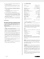
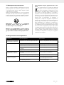
6. Technical data
AC motor......................................................220-240 V
~
50 Hz
Power consumption .........................................1200 Watt (S1*)
................................................................... 1500 Watt (S6 25%)
Idle speed n
0
..............................................................4800 min
-1
Hard metal saw blade ..........................ø 210 x ø 30 x 2,6 mm
Number of teeth .......................................................................24
Riving knife thickness ........................................................ 2.0 mm
Min. size of workpiece W x L x H ..................10 x 50 x 1 mm
Table size ............................................................. 485 x 445 mm
Table width extension .........................................485 x 515 mm
Table size max. . ..................................................485 x 630 mm
Cutting height max. 45° ................................................... 45 mm
Cutting height max. 90° ................................................... 48 mm
Tilting saw blade ......................................................... 0-45° left
Suction connection ........................................................ ø 35 mm
Weight .................................................................. approx. 14 kg
Machine size (with extension)
W x L x H ................................................. 485 x 630 x 440 mm
*S1: Continuous operation at constant load
**S6 25% operating mode:
Continuous duty with intermittent loading (operating time 10
min.)
In order avoid impermissible overheating of the motor, the mo-
tor should be driven for only 25% of the operating time with the
stipulated nominal power and must then continue to run with no
load for the remaining 75% of the operating time.
Noise
The total noise values were determined in accordance with
EN 62841.
Sound pressure level L
pA
............................................ 87.5 dB(A)
Uncertainty K
pA
......................................................................3 dB
Sound power level L
WA
............................................ 100.5 dB(A)
Uncertainty K
WA
.....................................................................3 dB
Wear hearing protection.
The effects of noise can cause a loss of hearing. Total vibration
values (vector sum - three directions) determined in accordance
with EN 62841.
NOTE: The specified device emissions values have been meas-
ured in accordance with a standardised test procedure and
can be used for comparison of one electric tool with another.
The specified device emissions values can also be used for an
initial estimation of the load.
WARNING: The noise emission values can vary from the
specified values during the actual use of the electric tool, de-
pending on the type and the manner in which the electric tool is
used, and in particular the type of workpiece being processed.
Implement measures to protect against noise nuisance. In do-
ing so, take into account the complete working process, includ-
ing the times when the electric tool is working without load or
switched off.
Suitable measures include regular maintenance and care of the
electric tool and the insertion tools, regular breaks as well as
proper planning of the working process.

9GB/CY
7. Before starting the equipment
• Open the packaging and remove the device carefully.
• Remove the packaging material as well as the packaging
and transport bracing (if available).
• Check that the delivery is complete.
• Check the device and accessory parts for transport dam-
age.
• If possible, store the packaging until the warranty period
has expired.
m WARNING
The device and packaging materials are not toys!
Children must not be allowed to play with plastic
bags, film and small parts! There is a risk of swal-
lowing and suffocation!
• The equipment must be securely installed, i.e. bolted down
on a workbench, base frame or similar. Use the holes on the
inner side of the frame legs for this.
• All covers and safety devices have to be properly fitted be-
fore the equipment is switched on.
• It must be possible for the blade to run freely.
• When working with wood that has been processed before,
watch out for foreign bodies such as nails or screws, etc.
• Before you press the On/Off switch check that the saw
blade is fitted correctly. Moving parts must run smoothly.
• Before you connect the equipment to the power supply make
sure the data on the rating plate are identical to the mains
data.
• Connect the equipment to a properly installed protective
contact socket, with at least 16 A circuit breaker.
8. Assembling the equipment
m WARNING: Disconnect the mains power plug before
maintaining, resetting or assembling the table saw.
8.1 Before assembling the equipment
• Place all parts supplied on a flat surface.
• Group equal parts.
NOTE:
• If compounds with a bolt (round head / or hexagon), hex
nuts and washers are backed up, the washer must be fitted
under the nut.
• Insert screws each from outside to inside. Secure connections
with nuts on the inside.
• Tighten the nuts and bolts during assembly only to the extent
that they can not fall down. If you tighten the nuts and bolts
prior to final assembly, final assembly can not be performed.
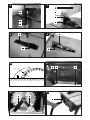
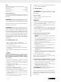
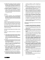
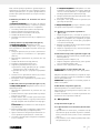
8.2 Fitting the table width extension (fig. 4-6)
1. Loosen the knurled screws (26) (fig. 5).
ATTENTION: Do not unscrew the knurled screws (26) too
far.
2. Feed the guide tubes (23) of the table width extension (22)
into the guide bushings (27) (see fig. 4/5).
3. Slide the end pieces (24) into the guide tubes (23) of the
table width extension (22) as shown in fig. 6.
4. Fasten the end pieces (24) with the screws (25) as shown
in Fig. 6.
5. Pull the table width extension (22) out completely and fas-
ten in place with the knurled screws (26) (Fig. 5).
6. Now fold out the support feet (30).
7. Align the table width extension (22) horizontally with the
table saw.
8. Loosen the lock nuts (29) on the respective support foot
(30) and adjust the height adjustment screw (28) as re-
quired.
9. Then retighten the lock nuts (29).
If you do not need the table width extension (22), fold the sup-
port feet (30) in.
8.3 Fitting/removing the saw blade guard
(fig. 7)
1. Place the saw blade guard (4) together with the screw (4a)
on the riving knife (3) from above, so that the screw sits
firmly in the hole of the riving knife (31).
2. Do not over-tighten the screw (4a). The saw blade guard
(4) must remain free to move.
3. Disassembly takes place in reverse order.
m WARNING: Before starting sawing, the saw blade
guard (4) must be lowered onto the material to be sawn.
After fitting, check that the saw blade guard (4) is function-
ing properly. Lift the saw blade guard and then release it. The
saw blade guard should automatically move back to its starting
position.
8.4 Removing/fitting the table inlay (fig. 8)
m WARNING: In the event of wear or damage the table
insert (6) must be replaced; otherwise there is an increased
danger of injury.
1. Move the saw blade into the bottom position (see 9.2).
2. Take off the saw blade guard (4).
3. Remove the table insert screws (32).
4. Remove the table insert (6).
5. Installation of the table insert (6) takes place in reverse
order.
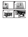
8.5 Setting the riving knife (fig. 9)
m WARNING: Pull out the mains plug.
m WARNING: The setting of the saw blade (5) must be
checked after every saw blade replacement.
1. Set the saw blade (5) to the max. cutting depth, move to
the 0° position and lock in place (see 9.2).
2. Remove the saw blade guard (4) (see 8.3).
3. Remove the table inlay (6) (see 8.4).
4. Loosen the fastening screws (33)
5. Align the riving knife (3) such that
a) the distance between the saw blade (5) and the splitter
(3) is max. 5 mm (fig. 10) and
b) the saw blade (5) is parallel to the splitter (3).
6. Retighten the fastening screws (33) and fit the table insert
(6) (see 8.4).
7. Fit the saw blade guard (4) again (see 8.3).

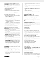
10 GB/CY
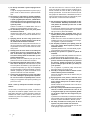
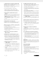
8.6 Fitting/replacing the saw blade (fig. 11, 12)
m WARNING: Pull out the mains plug and wear protective
gloves.
1. Remove the saw blade guard (4) (see 8.3).
2. Unscrew the screws (34) on the bottom saw blade cover
(35) and open it out.
3. Loosen the nut by applying the 19 mm ring spanner (21) to
the nut and holding the motor shaft in place with an 8 mm
ring spanner (20) (see fig. 12).
ATTENTION: Turn the nut in the direction of rotation of
the saw blade.
4. Take off the outer flange and pull the old saw blade down
and off the inner flange at an angle.
5. Clean the saw blade flange carefully with a wire brush
before installing the new saw blade.
6. Insert the new saw blade in the reverse sequence and
tighten.
m WARNING: Pay attention to the running direction.
The cutting angle of the teeth must point in the running di-
rection, i.e. forwards (see arrow on the saw blade guard
(4)).
7. Close the bottom saw blade cover (35) and tighten the
screws (34) again.
8. Refit the saw blade guard (4) and adjust it (see 8.3).
m WARNING: Check the protective devices before working
with the saw again.
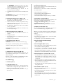
8.7 Fitting the parallel stop (fig, 2, 15)
1. Fasten the holder (16) to the table with the help of the lock-
ing knobs (15) and the clamping plates (15a).
2. Make sure that the holder (16) is aligned parallel to the
saw blade (5). If necessary, readjust it with the aid of the
scale (38).
3. Slide the sliding block along the groove (37) in the stop
rail (17).
4. Fasten the stop rail (17) to the holder (16) with the help of
the screws (16a).
8.8 Fitting the transverse stop (fig. 18)
1. Slide the transverse stop (2) in the groove (40) of the saw
table (1).
2. Loosen the turning handle (19).
3. Turn the transverse stop (2) until the arrow points to the
desired angle.
4. Retighten the turning handle (19).
8.9 Chip extraction (fig. 13)
ATTENTION: Only operate the device with an extraction
system.
Connect a suitable chip extraction system (not included in the
scope of delivery) to the suction port (36).
ATTENTION: Check and clean the suction channels at regu-
lar intervals.
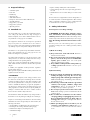
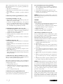
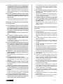
8.10 Stable fastening (fig. 25)
The machine must be securely installed, i.e. bolted down on a
workbench, machine stand or similar, as shown in fig. 25.
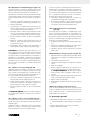
Use the bracket for workbench mounting (42), the screws (43)
and the washers (44) to do so.
9. Handling the equipment
9.1 Switches (fig. 1)
9.1.1 On/off switch (11)
• It is possible to switch the saw on by pressing the green “I”
button. Before starting sawing, wait until the saw blade has
reached its maximum speed.
• In order to switch the saw off again, it is necessary to press
the red “0” button.
9.1.2 Overload switch (10)
The device motor is protected against overload with an over-
load switch (10).
In the event of the nominal current being exceeded, the over-
load switch (10) switches the device off.
If this happens, proceed as follows:
• Let the device cool down for several minutes.
• Press the overload switch (10).
• Switch the device on by pressing the green “I” button.
9.2 Setting the cutting depth (fig. 1)
The saw blade (5) can be adjusted to the required cutting
depth by turning the hand wheel (8).
• Counter-clockwise: Greater cutting depth
• Clockwise: Smaller cutting depth
Check the setting with a test cut.
9.3 Setting the angle (fig. 14)
Angled cuts of 0°-45° to the left of the parallel stop (7) can be
carried out with the circular table saw.
m Before making every cut, check that no collision can occur
between the stop rail (17), transverse stop (2) and the saw
blade (5).
1. Loosen the locking handle (9).
2. Set the desired angle on the scale by turning the hand wheel
(8).
3. Lock the locking handle (9) at the desired angle setting.
9.4 Using the parallel stop (fig. 2, 15-17)
9.4.1 Stop heights (fig. 15, 16)
• The stop rail (17) of the parallel stop (7) has two guide sur-
faces at different heights.
• Depending on the thickness of the material to be cut, the stop
rail (17) must be used as shown in Fig. 15 for thick material
(workpiece thickness exceeding 25 mm) and as shown in
Fig. 16 for thin material (workpiece thickness below 25 mm).

11GB/CY
9.4.2 Shifting the stop rail (fig. 15, 16)
1. In order to move the stop rail (17) to the lower guide sur-
face, loosen the two screws (16a) to release the stop rail
(17) from the holder (16).
2. Pull the stop rail (17) along the groove and out.
3. Turn the stop rail (17) and slide the sliding block along the
second groove (39).
4. Shifting to the higher guide surface must be carried out in
the same way.
9.4.3 Cutting width (fig. 15, 16)
• The parallel stop (7) must be used when cutting sections of
wood lengthways.
• The parallel stop (7) can be mounted on both sides of the
saw table (1).
• The parallel stop (7) can be set to the required dimension
with the aid of the scale (38) on the saw table (1).
• Tighten the two locking knobs (15) to fasten the parallel stop
(7) in place.
• Perform a test cut to measure the width before cutting the
real workpiece. In this way you avoid inaccuracies with the
scale or the setting.
9.4.4 Setting the stop length (fig. 15, 17)
In order to avoid the material to be cut becoming jammed, the
stop rail (17) can slide in a longitudinal direction.
Rule of thumb: The rear edge of the stop should intersect an
imaginary line that starts roughly at the centre of the saw blade
and runs to the rear at 45°:
1. Set the required cutting width.
2. Loosen the screws (16a) and slide the stop rail (17) far
enough forward that it touches the imaginary 45° line.
3. Tighten the screws (16a) again.
9.5 Using the transverse stop (fig. 18)
When trimming, the transverse stop (2) must be extended from
the parallel stop (7) with the stop rail (17) (fig. 18).
9.5.1 Extending the transverse stop
1. Remove the stop rail (17) from the parallel stop (7). To do
so, loosen the screws (16a) and release the stop rail (17)
from the holder (16).
2. Slide the sliding block along the groove in the stop rail
(17).
3. Fasten the stop rail (17) with the help of the knurled screws
(18) on the transverse stop (2).
ATTENTION
Do not push the stop rail (17) too far toward to the saw blade
(5). The distance between the stop rail (17) and the saw blade
(5) should be approx. 2 cm.
10. Using the equipment
Working instructions
• After each new adjustment it is advisable to carry out a trial
cut in order to check the set dimensions.
• After switching on the saw, wait for the blade to reach its
maximum speed of rotation before commencing with the cut.
• Take extra care when starting the cut.
• Never use the equipment without the suction function.
• Regularly check and clean the suction channels.
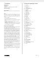
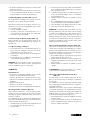
10.1 Making longitudinal cuts (fig. 19)
Longitudinal cutting is when you use the saw to cut along the
grain of the wood. One edge of the workpiece will be pressed
against the parallel stop (7), while the flat side lies on the saw
table (1).
The saw blade guard (4) must always be lowered over the
workpiece. When making a longitudinal cut, never adopt a
working position that is in line with the cutting direction.
1. Set the parallel stop (7) in accordance with the workpiece
height and the desired width (see 9.4).
2. Switch on the saw.
3. Place your hands (with fingers closed) flat on the work-
piece and push the workpiece along the parallel stop (7)
and into the saw blade (5).
4. Guide at the side with your left or right hand (depending
on the position of the parallel stop) only as far as the front
edge of the saw blade guard (4).
5. Always push the workpiece through to the end of the split-
ter (3).
6. The offcut piece remains on the saw table (1) until the saw
blade (5) is back in its position of rest.
7. Secure long workpieces against falling off at the end of the
cut (e.g. with a roller stand etc.).
ATTENTION: The parallel stop must be set parallel with the
saw blade (see 8.7). Check the alignment and ensure that the
parallel stop is firmly seated at regular intervals, particularly
during use and after longer periods not in use. Tighten the
screw again and adjust the parallel stop (see 9.4.3) if neces-
sary. Vibrations can loosen screws and change the position of
the parallel stop.
10.1.1 Cutting narrow workpieces (fig. 20)
Be sure to use a push stick (14) when making longitudinal cuts
in workpieces smaller than 120 mm in width. A push stick (14)
is supplied with the saw! Replace a worn or damaged push
stick immediately.
1. Adjust the parallel stop (7) to the width of workpiece you
require (see 9.4).
2. Feed in the workpiece with two hands. Always use the push
stick (14) in the area of the saw blade.
3. Always push the workpiece through to the end of the split-
ter (3).
m WARNING: With short workpieces, use the push stick
(14) from the beginning.
10.1.2 Cutting extremely narrow workpieces
(fig. 21)
Be sure to use a push block when making longitudinal cuts in
very narrow workpieces with a width of 30 mm and less. There
is no push block supplied with the saw! (Available from your
specialist dealer) Replace the push block without delay when
it becomes worn.
When sawing workpieces, these can become jammed be-
tween the parallel stop and the saw blade, be caught by the
saw blade, and be thrown from the machine. Therefore, the low
guide face of the parallel stop is best used in this case (see fig.
16). If required, change over the stop rail (see 9.4.2).

12 GB/CY
1. Adjust the parallel stop to the width of workpiece you re-
quire.
2. Use the push block to press the workpiece against the
stop rail and push the workpiece with the push stick (14)
through to the end of the splitter.
10.1.3 Making angular cuts (fig. 22)
Angular cuts must always be made using the parallel stop (7).
The parallel stop (7) must always be fitted to the right of the
saw blade. Otherwise, workpieces can become jammed be-
tween the parallel stop and the saw blade during sawing and
ejected at speed.
1. Set the saw blade (5) to the desired angle (see 9.3).
2. Set the parallel stop (7) in accordance with the workpiece
width and height (see 9.4).
3. Carry out the cut in accordance with the workpiece width
(see 10.1).
10.2 Making transverse cuts (fig. 23)
1. Push the transverse stop (2) into the groove (40) of the saw
table and set it to the required angle (see 9.5).
2. Use the stop rail (17).
3. Press the workpiece firmly against the transverse stop (2).
4. Switch on the saw.
5. Push the transverse stop (2) and the workpiece toward the
saw blade (5) in order to make the cut.
m WARNING: Always hold the guided part of the work-
piece. Never hold the part which is to be cut off.
6. Push the transverse stop (2) forward until the workpiece is
cut all the way through.
7. Switch off the saw again.
8. Do not remove the offcut until the saw blade has stopped
rotating.
10.3 Cutting particle boards
To prevent the cutting edges from cracking when working with
particle boards, you should not set the saw blade (5) more
than 5 mm greater than the thickness of the workpiece (also
see 9.2).
11. Transporting the equipment (fig. 24)
• Turn off the power tool before any transport and disconnect
it from the power supply.
• Lower the saw blade (5) as far as possible.
• Wind up the mains cable (41).
• Carry the power tool with both hands by the fixed saw table
(1). Never use the table width extension to carry the power
tool.
• Protect the power tool from knocks, bumps and strong vibra-
tions, such as during transport in vehicles.
• Secure the power tool against overturning and sliding.
• Never use the safety devices for handling or transporting
purposes.
12. Maintaining the equipment
m WARNING: Prior to any adjustment, maintenance or ser-
vice work disconnect the mains power plug!
12.1 General maintenance measures
• Keep protective devices, air vents, suction openings and the
motor housing as free of dust and dirt as possible. Remove
shavings and dust with a vacuum cleaner and a brush. In ad-
dition, blow it out with low-pressure compressed air.
• We recommend that you clean the equipment immediately
after you use it.
• Clean the equipment regularly with a damp cloth and some
soft soap. Do not use cleaning agents or solvents; these may
be aggressive to the plastic parts in the equipment. Ensure
that no water can get into the interior of the equipment.
• In order to extend the service life of the tool, oil the rotary
parts once monthly. Do not oil the motor.
12.2 Carbon brushes
• In case of excessive sparking, have the carbon brushes
checked only by an electrical specialist.
IMPORTANT: The carbon brushes must not be replaced by
anyone but an electrical specialist.
Service information
Please note that the following parts of this product are sub-
ject to normal or natural wear and that the following parts are
therefore also required for use as consumables.
Wear parts*: carbon brushes, table inlay, push stick, saw blade
* Not necessarily included in the scope of delivery!
13. Storing the equipment
Store the device and its accessories in a dark, dry and frost-
proof place that is inaccessible to children. The optimum stor-
age temperature is between 5 and 30˚C.
Store the electrical tool in its original packaging.
Cover the electrical tool in order to protect it from dust and
moisture.
Store the operating manual with the electrical tool.
14. Electrical connection
The electrical motor installed is connected and
ready for operation. The connection complies with
the applicable VDE and DIN provisions. The cus-
tomer‘s mains connection as well as the extension
cable used must also comply with these regula-
tions.
Important information
In the event of an overloading the motor will switch itself
off. After a cool-down period (time varies) the motor can be
switched back on again.

13GB/CY
Damaged electrical connection cable
The insulation on electrical connection cables is often dam-
aged.
This may have the following causes:
• Passage points, where connection cables are passed
through windows or doors
• Kinks where the connection cable has been improperly fas-
tened or routed
• Places where the connection cables have been cut due to
being driven over
• Insulation damage due to being ripped out of the wall outlet
• Cracks due to the insulation ageing
Such damaged electrical connection cables must not be used
and are life-threatening due to the insulation damage.
Check the electrical connection cables for damage regularly.
Make sure that the connection cable does not hang on the
power network during the inspection.
Electrical connection cables must comply with the applicable
VDE and DIN provisions. Only use connection cables with the
marking “H05VV-F”.
The printing of the type designation on the connection cable
is mandatory.
If it is necessary to replace the connection cable, this must
be done by the manufacturer or their representative to avoid
safety hazards.
AC motor:
• The mains voltage must be 220-240 V
~
.
• Extension cables up to 25 m length must have a cross sec-
tion of 1.5 mm
2
.
Connections and repairs of electrical equipment may only be
carried out by an electrician. Please provide the following in-
formation in the event of any enquiries:
• Type of current for the motor
• Machine data - type plate
• Motor data - type plate
15. Disposal and recycling
The equipment is supplied in packaging to prevent it from be-
ing damaged in transit. The raw materials in this packaging
can be reused or recycled.
The equipment and its accessories are made of various types
of material, such as metal and plastic. Defective components
must be disposed of as special waste. Ask your dealer or your
local council.
The packaging is wholly composed of
environmentally-friendly materials that can be
disposed of at a local recycling centre.
Contact your local refuse disposal authority for
more details of how to dispose of your worn-out
electrical devices.
Old devices must not be disposed of with house-
hold waste!
This symbol indicates that this product must not be dis-
posed of together with domestic waste in compliance
with the Directive (2012/19/EU) pertaining to waste
electrical and electronic equipment (WEEE). This prod-
uct must be disposed of at a designated collection point. This
can occur, for example, by handing it in at an authorised col-
lecting point for the recycling of waste electrical and elec-
tronic equipment. Improper handling of waste equipment may
have negative consequences for the environment and human
health due to potentially hazardous substances that are often
contained in electrical and electronic equipment. By properly
disposing of this product, you are also contributing to the ef-
fective use of natural resources. You can obtain information
on collection points for waste equipment from your municipal
administration, public waste disposal authority, an authorised
body for the disposal of waste electrical and electronic equip-
ment or your waste disposal company.

14 GB/CY
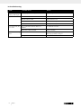
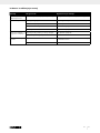
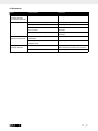
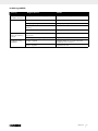
16. Troubleshooting
Fault Possible causes Action
Blade dissolves after
switching off the engine
To slightly tightened fastening nut Tighten the right hand thread nut
Engine will not start Failure mains fuse Check mains fuse
Defective extension cable Replace extension cord
Connections on motor or switch not in order Repair by electrical specialist
Motor or switch faulty Repair by electrical specialist
Motor will not work, the
fuse is active
Cross section of the extension cable is not
sufficient
See „Electrical connection“
Overload by a blunt saw blade Change saw blade
Fire marks on the cutting
surface
Blunt saw blade Have saw blade sharpened (only by an authorised
sharpening specialist) or change it
Wrong saw blade Change saw blade
Pagina se încarcă ...
Pagina se încarcă ...
Pagina se încarcă ...
Pagina se încarcă ...
Pagina se încarcă ...
Pagina se încarcă ...
Pagina se încarcă ...
Pagina se încarcă ...
Pagina se încarcă ...
Pagina se încarcă ...
Pagina se încarcă ...
Pagina se încarcă ...
Pagina se încarcă ...
Pagina se încarcă ...
Pagina se încarcă ...
Pagina se încarcă ...
Pagina se încarcă ...
Pagina se încarcă ...
Pagina se încarcă ...
Pagina se încarcă ...
Pagina se încarcă ...
Pagina se încarcă ...
Pagina se încarcă ...
Pagina se încarcă ...
Pagina se încarcă ...
Pagina se încarcă ...
Pagina se încarcă ...
Pagina se încarcă ...
Pagina se încarcă ...
Pagina se încarcă ...
Pagina se încarcă ...
Pagina se încarcă ...
Pagina se încarcă ...
Pagina se încarcă ...
Pagina se încarcă ...
Pagina se încarcă ...
Pagina se încarcă ...
Pagina se încarcă ...
Pagina se încarcă ...
Pagina se încarcă ...
Pagina se încarcă ...
Pagina se încarcă ...
Pagina se încarcă ...
Pagina se încarcă ...
Pagina se încarcă ...
Pagina se încarcă ...
Pagina se încarcă ...
Pagina se încarcă ...
Pagina se încarcă ...
Pagina se încarcă ...
Pagina se încarcă ...
Pagina se încarcă ...
Pagina se încarcă ...
Pagina se încarcă ...
Pagina se încarcă ...
Pagina se încarcă ...
Pagina se încarcă ...
Pagina se încarcă ...
Pagina se încarcă ...
Pagina se încarcă ...
Pagina se încarcă ...
Pagina se încarcă ...
Pagina se încarcă ...
Pagina se încarcă ...
Pagina se încarcă ...
Pagina se încarcă ...
Pagina se încarcă ...
Pagina se încarcă ...
Pagina se încarcă ...
Pagina se încarcă ...
Pagina se încarcă ...
Pagina se încarcă ...
-
 1
1
-
 2
2
-
 3
3
-
 4
4
-
 5
5
-
 6
6
-
 7
7
-
 8
8
-
 9
9
-
 10
10
-
 11
11
-
 12
12
-
 13
13
-
 14
14
-
 15
15
-
 16
16
-
 17
17
-
 18
18
-
 19
19
-
 20
20
-
 21
21
-
 22
22
-
 23
23
-
 24
24
-
 25
25
-
 26
26
-
 27
27
-
 28
28
-
 29
29
-
 30
30
-
 31
31
-
 32
32
-
 33
33
-
 34
34
-
 35
35
-
 36
36
-
 37
37
-
 38
38
-
 39
39
-
 40
40
-
 41
41
-
 42
42
-
 43
43
-
 44
44
-
 45
45
-
 46
46
-
 47
47
-
 48
48
-
 49
49
-
 50
50
-
 51
51
-
 52
52
-
 53
53
-
 54
54
-
 55
55
-
 56
56
-
 57
57
-
 58
58
-
 59
59
-
 60
60
-
 61
61
-
 62
62
-
 63
63
-
 64
64
-
 65
65
-
 66
66
-
 67
67
-
 68
68
-
 69
69
-
 70
70
-
 71
71
-
 72
72
-
 73
73
-
 74
74
-
 75
75
-
 76
76
-
 77
77
-
 78
78
-
 79
79
-
 80
80
-
 81
81
-
 82
82
-
 83
83
-
 84
84
-
 85
85
-
 86
86
-
 87
87
-
 88
88
-
 89
89
-
 90
90
-
 91
91
-
 92
92


Parkside PMTS 210 A1 Operating And Safety Instructions Manual
- Categorie
- Unelte electrice
- Tip
- Operating And Safety Instructions Manual
în alte limbi
- Deutsch: Parkside PMTS 210 A1
Lucrări conexe
-
Parkside PKS 1500 A2 Operating And Safety Instructions Manual
-
Parkside PHKS 1300 A1 Operation And Safety Notes Translation Of Original Operation Manual
-
Parkside 3901227981 Operating And Safety Instructions Manual
-
Parkside PKS 1500 A1 Operating And Safety Instructions Manual
-
-
-
-
Alte documente
-
Hilti SCW 22-A Manual de utilizare
-
Hikoki C 6SS Brushless Circular Saw Manual de utilizare
-
-
Hikoki c6bu2 Manual de utilizare
-
Scheppach HM100MP Manual de utilizare
-
Ryobi RPLS18X Manual de utilizare
-
-
ATIKA PTK 250 S Original Instructions Manual
-
-
EINHELL 43.405.10 Manual de utilizare