
PORTABLE
AIR CONDITIONER
USER
MANUAL
TTPSL-09CW
Ver. 2023
HU MKD
BIH/
MNE RO SLO SRBENG BG GR HR

OPERATING INSTRUCTION
Note: All the pictures in this manual are just schematic diagrams, the actual is the standard. Please read
this owner’s manual carefully and thoroughly before operating the unit! Take care of this manual for future
reference.
UPUTE ZA UPOTREBU
Napomena: Sve slike u ovom priručniku su samo shematski dijagrami, fizički proizvod je standard. Molimo
Vas da pažljivo i temeljito pročitate ovo uputstvo za upotrebu prije korištenja uređaja! Čuvajte ovaj priručnik
za buduće korištenje.
FELHASZNÁLÓI KÉZIKÖNYV
Megjegyzés: A kézikönyvben található képek csak sematikus ábrák, az aktuális a szabvány. Kérjük, figyelmesen
olvassa el ezt a kézikönyvet mielőtt működtetné az eszközt! Őrizze meg ezt a kézikönyvet a későbbiekre is.
ΕΓΧΕΙΡΙΔΙΟ ΧΡΉΣΉΣ
Σημείωση: Οι εικόνες στο παρόν εγχειρίδιο είναι σχεδιαγράμματα, ανατρέξτε στο πραγματικό προϊόν. Διαβάστε
προσεκτικά τις προφυλάξεις στο παρόν εγχειρίδιο προτού θέσετε τη μονάδα σε λειτουργία! Φυλάξτε το παρόν
εγχειρίδιο για μελλοντική χρήση.
ИНСТРУКЦИЯ ЗА УПОТРЕБА
Забележка: Всички снимки в тази инструкция са само схематични диаграми, действителните са
стандартните. Моля, прочетете внимателно тази инструкция за употреба преди да започнете работа с
уреда! Запазете тази инструкция за бъдещи справки
PRIROČNIK ZA UPORABO
Opomba: Vse slike v tem priročniku so le shematske risbe, dejansko stanje je standard. Prosimo, da pred
uporabo skrbno in temeljito preberete ta priročnik za uporabo! Priročnik shranite za kasnejšo uporabo.
MANUAL DE UTILIZARE
Nota: Fotografiile din acest manual sunt doar diagrame schematice. Vă rugăm să citiți “Manualul de Utilizare”
cu atenție, înainte de a utiliza aerul condiționat, pentru a asigura funcționarea corespunzătoare. Păstrați
manualul pentru referințe ulterioare.
ENG
HR
HU
GR
BG
UPUTSTVO ZA UPOTREBU
Napomena: Sve slike u ovom priručniku su samo šematski dijagrami, fizički proizvod je standard. Molimo Vas
da pažljivo i temeljno pročitate ovo uputstvo za upotrebu prije korišćenja uređaja! Sačuvajte ovo uputstvo za
buduću upotrebu.
BIH/
MNE
SLO
RO
УПАТСТВО ЗА УПОТРЕБА
Напомена: Сите слики во овој прирачник се само шематски дијаграми, физичкиот производ е
стандард. Ве молиме внимателно и теменлно да го причитате ова упатство за употреба пред
користење на уредот! Сочувајте го ова упатство за идна употреба.
MKD
UPUTSTVO ZA UPOTREBU
Napomena: Sve slike u ovom priručniku su samo šematski dijagrami, fizički proizvod je standard. Molimo
Vas da pažljivo i temeljno pročitate ovo uputstvo za upotrebu pre korišćenja uređaja! Sačuvajte ovo
uputstvo za buduću upotrebu.
SRB

3
ENG
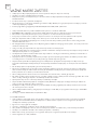
• Disconnect the appliance from its power source during service and when replacing parts and cleaning.
• The appliance shall not be installed in the laundry.
• Please note: Check the nameplate for the type of refrigerant gas used in your appliance.
• Specific information regarding appliances with refrigerant gas.
• The appliance is recommended not to pierce the cooling circuit of the machine. At the end of its useful life,
deliver the appliance to a special waste collection centre for disposal.
• GWP(Global Warming Potential): R410A: 2088, R134a: 1430, R290: 3, R32: 675.
• This hermetically sealed system contains fluoridated greenhouse gases.
• ENVIRONMENTAL INFORMATION: This unit contains fluoridated greenhouse gases covered by the Kyoto
Protocol.
• Do not use this unit for functions other than those described in this instruction manual.
• Make sure the plug is plugged firmly and completely into the outlet. It can result in the risk of electric shock
or fire.
• Do not plug other appliances into the same outlet, it can result in the risk of electric shock.
• Do not disassemble or modify the appliance or the power cord, it can result in the risk of electric shock or fire.
All other services should be referred to a qualified technician.
• Do not place the power cord or appliance near a heater, radiator, or other heat source. It can result in the risk
of electric shock or fire.
• This unit is equipped with a cord that has a earthed wire connected to an earthed pin or grounding tab. The
plug must be plugged into a socket that is properly installed and earthed. Do not under any circumstances
cut or remove the earthed pin or grounding tab from this plug.
• The unit should be used or store in such a way that it is protected from moisture e.g. condensation, splashed
water, etc. Unplug unit immediately if this occurs.
• Always transport your appliance in a vertical position and place on a stable, level surface during use. If the
unit is transported laying on its side it should be stood up and left unplugged for 6 hours.
• Always use the switch on the control panel or remote control to turn the unit off, and do not start or stop
operation by plugging in or unplugging the power cord. It can result in the risk of electric shock.
• Do not touch the buttons on the control panel with your wet and damp fingers.
• Do not use hazardous chemicals to clean or come into contact with the unit. To prevent damage to the surface
finish, use only a soft cloth to clean the appliance. Do not use wax, thinner, or a strong detergent. Do not use
the unit in the presence of inflammable substance or vapour such as alcohol, insecticides, gasoline, etc.
• If the appliance is making unusual sounds or is emitting smoke or an unusual odor, unplug it immediately.
• Do not clean the unit with water. Water can enter the unit and damage the insulation, creating a shock hazard.
If water enters the unit, unplug it immediately and contact Customer Service.
• Utilize two or more people to lift and install the unit.
• Always grasp the plug when plugging in or unplugging the appliance. Never unplug by pulling on the cord.
It can result in the risk of electrical shock and damage.
• Install the appliance on a sturdy, level floor capable of supporting up to 110lbs(50kg). Installation on a weak
or unlevel floor can result in the risk of property damage and personal injury.
• If the appliance have the Wi-Fi function , the transmission power: less than 20dBm, and the radio frequency
range is: 2412MHz-2472MHz.
• The appliance is compliant with the RE Directive (2014/53/EU).
According the EN standard:
• This appliance can be used by children aged from 8 years and above and persons with reduced physical,
sensory or mental capabilities or lack of experience and knowledge if they have been given supervision or
instruction concerning use of the appliance in a safe way and understand the hazards involved.
• Children shall not play with the appliance.
• Cleaning and user maintenance shall not be made by children without supervision.
• If the supply cord is damaged, it must be replaced by the manufacturer, its service agent or a similarly
qualified person in order to avoid a hazard.
• The appliance shall be installed in accordance with national wiring regulations.
• When the fuse is blown/circuit breaker is tripped, check the house fuse/circuit breaker box and replace fuse
or reset breaker
• Details of type and rating of fuses : T; 3.15A; 250VAC.
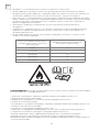
IMPORTANT SAFEGUARDS

4
ENG
According the IEC standard:
• This appliance is not intended for use by persons (including children) with reduced physical, sensory or
mental capabilities, or lack of experience and knowledge, unless they have been given supervision or
instruction concerning use of the appliance by a person responsible for their safety.
• Children should be supervised to ensure that they do not play with the appliance.
• If the supply cord is damaged, it must be replaced by the manufacturer, its service agent or similarly qualified
persons in order to avoid a hazard.
• The appliance shall be installed in accordance with national wiring regulations.
Specific information regarding appliances with R290 refrigerant gas
• Thoroughly read all of the warnings.
• When defrosting and cleaning the appliance, do not use any tools other than those recommended by the
manufacturing company.
• The appliance must be placed in an area without any continuous sources of ignition (for example: open
flames, gas or electrical appliances in operation).
• Do not puncture and do not burn.
• Refrigerant gases can be odourless.
• The appliance must be installed, used and stored in an area that is greater than 13 m2.
• R290 is a refrigerant gas that complies with the European directives on the environment. Do not puncture any
part of the refrigerant circuit.
• If the appliance is installed, operated or stored in a non-ventilated area, the room must be designed to
prevent the accumulation of refrigerant leaks resulting in a risk of fire or explosion due to ignition of the
refrigerant caused by electric heaters, stoves, or other sources of ignition.
• The appliance must be stored in such a way as to prevent mechanical failure.
• Individuals who operate or work on the refrigerant circuit must have the appropriate certification issued by an
accredited organization that ensures competence in handling refrigerants according to a specific evaluation
recognized by associations in the industry.
• Repairs must be performed based on the recommendations from the manufacturing company.
• Maintenance and repairs that require the assistance of other qualified personnel must be performed under
the supervision of an individual specified in the use of flammable refrigerants.
• Do not use means to accelerate the defrosting process or to clean, other than those recommended by the
manufacturer.
• The appliance shall be stored in a room without continuously operating open flames (for example an
operating gas appliance) or other potential ignition sources (for example an operating electric heater, hot
surfaces).
• All the work men who are engaging in the refrigeration system should bear the valid certification awarded
by the authoritative organization and the qualification for dealing with the refrigeration system recognized by
this industry. If it needs other technician to maintain and repair the appliance, they should be supervised by
the person who bears the qualification for using the flammable refrigerant.
• It can only be repaired by the method suggested by the equipment’s manufacturer.
• Do not pierce or burn.
• Be aware that the refrigerants may not contain an odour.
• Compliance with national gas regulations shall be observed.
• Keep ventilation openings clear of obstruction.
• The appliance shall be stored so as to prevent mechanical damage from occurring.
• A warning that the appliance shall be stored in a well-ventilated area where the room size corresponds to the
room area as specified for operation.
• Any person who is involved with working on or breaking into a refrigerant circuit should hold a current valid
certificate from an industry-accredited assessment authority, which authorizes their competence to handle
refrigerants safely in accordance with an industry recognized assessment specification.
• Servicing shall only be performed as recommended by the equipment manufacturer.
• Maintenance and repair requiring the assistance of other skilled personnel shall be carried out under the
supervision of the person competent in the use of flammable refrigerants.
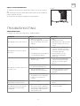
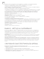
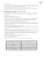
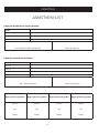
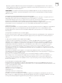
• Appliance should be installed, operated and stored in a room with a floor area larger than the one indicated
in the chart .

5
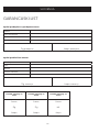
ENG
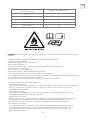
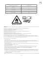
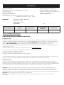
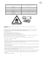
Quantity of R290 gas in charge (see rating
label on the appliance) (g)
Minimum size of the site for use and storage
(m²)
m<152 4
152≤m≤185 9
186≤m≤225 11
226≤m≤270 13
271≤m≤290 14
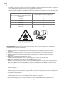
WARNING: System contains refrigerant under very high pressure. The system must be serviced by qualified
persons only.
1. Transport of equipment containing flammable refrigerants (Annex CC.1)
Compliance with the transport regulations.
2. Marking of equipment using signs(Annex CC.2)
Compliance with local regulations.
3. Disposal of equipment using flammable refrigerants(Annex CC.3)
Compliance with national regulations.
4. Storage of equipment/appliances (Annex CC.4)
The storage of equipment should be in accordance with the manufacturer’s instructions.
5. Storage of packed (unsold) equipment(Annex CC.5)
Storage package protection should be constructed such that mechanical damage to the equipment inside the
package will not cause a leak of the refrigerant charge.
The maximum number of pieces of equipment permitted to be stored together will be determined by local
regulations.
6. Information on servicing(Annex DD.3)
1) Checks to the area
Prior to beginning work on systems containing flammable refrigerants, safety checks are necessary to ensure
that the risk of ignition is minimised. For repair to the refrigerating system, the following precautions shall be
complied with prior to conducting work on the system.
2) Work procedure
Work shall be undertaken under a controlled procedure so as to minimise the risk of a flammable gas or
vapour being present while the work is being performed.
3) General work area
All maintenance staff and others working in the local area shall be instructed on the nature of work being
carried out. Work in confined spaces shall be avoided. The area around the workspace shall be sectioned off.
Ensure that the conditions within the area have been made safe by control of flammable material.
4) Checking for presence of refrigerant
The area shall be checked with an appropriate refrigerant detector prior to and during work, to ensure the
technician is aware of potentially flammable atmospheres. Ensure that the leak detection equipment being

6
ENG
used is suitable for use with flammable refrigerants, i.e. non-sparking, adequately sealed or intrinsically safe.
5) Presence of fire extinguisher
If any hot work is to be conducted on the refrigeration equipment or any associated parts, appropriate fire
extinguishing equipment shall be available to hand. Have a dry powder or CO2 fire extinguisher adjacent to
the charging area.
6) No ignition sources
No person carrying out work in relation to a refrigeration system which involves exposing any pipe work that
contains or has contained flammable refrigerant shall use any sources of ignition in such a manner that it may
lead to the risk of fire or explosion. All possible ignition sources, including cigarette smoking, should be kept
sufficiently far away from the site of installation, repairing, removing and disposal, during which lammable
refrigerant can possibly be released to the surrounding space. Prior to work taking place, the area
around the equipment is to be surveyed to make sure that there are no flammable hazards or ignition risks.
“No Smoking” signs shall be displayed.
7) Ventilated area
Ensure that the area is in the open or that it is adequately ventilated before breaking into the system or
conducting any hot work. A degree of ventilation shall continue during the period that the work is carried
out. The ventilation should safely disperse any released refrigerant and preferably expel it externally into the
atmosphere.
8) Checks to the refrigeration equipment
Where electrical components are being changed, they shall be fit for the purpose and to the correct
specification. At all times the manufacturer’s maintenance and service guidelines shall be followed. If in doubt
consult the manufacturer’s technical department for assistance.
The following checks shall be applied to installations using flammable refrigerants:
– The charge size is in accordance with the room size within which the refrigerant containing parts are installed;
– The ventilation machinery and outlets are operating adequately and are not obstructed;
– If an indirect refrigerating circuit is being used, the secondary circuit shall be checked for the presence of
refrigerant;
– Marking to the equipment continues to be visible and legible. Markings and signs that are illegible shall be
corrected;
– Refrigeration pipe or components are installed in a position where they are unlikely to be exposed to any
substance which may corrode refrigerant containing components, unless the components are constructed of
materials which are inherently resistant to being corroded or are suitably protected against being so corroded.
9) Checks to electrical devices
Repair and maintenance to electrical components shall include initial safety checks and component inspection
procedures. If a fault exists that could compromise safety, then no electrical supply shall be connected to
the circuit until it is satisfactorily dealt with. If the fault cannot be corrected immediately but it is necessary to
continue operation, an adequate temporary solution shall be used. This shall be reported to the owner of the
equipment so all parties are advised.
Initial safety checks shall include:
• That capacitors are discharged: this shall be done in a safe manner to avoid possibility of sparking;
• That there no live electrical components and wiring are exposed while charging, recovering or purging the
system;
• That there is continuity of earth bonding.
7. Repairs to sealed components(Annex DD.4)
1) During repairs to sealed components, all electrical supplies shall be disconnected from the equipment
being worked upon prior to any removal of sealed covers, etc. If it isabsolutely necessary to have an electrical
supply to equipment during servicing, then a permanently operating form of leak detection shall be located at
the most critical point to warn of a potentially hazardous situation.
2) Particular attention shall be paid to the following to ensure that by working on electrical components, the
casing is not altered in such a way that the level of protection is affected.
This shall include damage to cables, excessive number of connections, terminals not made to original
specification, damage to seals, incorrect fitting of glands, etc.
Ensure that apparatus is mounted securely.
Ensure that seals or sealing materials have not degraded such that they no longer serve the purpose of
preventing the ingress of flammable atmospheres. Replacement parts shall be in accordance with the
manufacturer’s specifications.

7
ENG
NOTE: The use of silicon sealant may inhibit the effectiveness of some types of leak detection equipment.
Intrinsically safe components do not have to be isolated prior to working on them.
8. Repair to intrinsically safe components (Annex DD.5)
Do not apply any permanent inductive or capacitance loads to the circuit without ensuring that this will not
exceed the permissible voltage and current permitted for the equipment in use.
Intrinsically safe components are the only types that can be worked on while live in the presence of a flammable
atmosphere. The test apparatus shall be at the correct rating.
Replace components only with parts specified by the manufacturer. Other parts may result in the ignition of
refrigerant in the atmosphere from a leak.
9. Cabling(Annex DD.6)
Check that cabling will not be subject to wear, corrosion, excessive pressure, vibration, sharp edges or any other
adverse environmental effects. The check shall also take into account the effects of aging or continual vibration
from sources such as compressors or fans.
10. Detection of flammable refrigerants(Annex DD.7)
Under no circumstances shall potential sources of ignition be used in the searching for or detection of
refrigerant leaks. A halide torch (or any other detector using a naked flame) shall not be used.
11. Leak detection methods(Annex DD.8)
The following leak detection methods are deemed acceptable for systems containing flammable refrigerants.
Electronic leak detectors shall be used to detect flammable refrigerants, but the sensitivity may not be adequate,
or may need re-calibration. (Detection equipment shall be calibrated in a refrigerant-free area.) Ensure that the
detector is not a potential source of ignition and is suitable for the refrigerant used. Leak detection equipment
shall be set at a percentage of the LFL of the refrigerant and shall be calibrated to the refrigerant employed and
the appropriate percentage of gas (25 % maximum) is confirmed.
Leak detection fluids are suitable for use with most refrigerants but the use of detergents containing chlorine
shall be avoided as the chlorine may react with the refrigerant and corrode the copper pipe-work.
If a leak is suspected, all naked flames shall be removed/ extinguished.
If a leakage of refrigerant is found which requires brazing, all of the refrigerant shall be recovered from the
system, or isolated (by means of shut off valves) in a part of the system remote from the leak. Oxygen free
nitrogen (OFN) shall then be purged through the system both before and during the brazing process.
12. Removal and evacuation(Annex DD.9)
When breaking into the refrigerant circuit to make repairs – or for any other purpose – conventional procedures
shall be used. However, it is important that best practice is followed since flammability is a consideration. The
following procedure shall be adhered to:
• Remove refrigerant;
• Purge the circuit with inert gas;
• Evacuate;
• Purge again with inert gas;
• Open the circuit by cutting or brazing.
The refrigerant charge shall be recovered into the correct recovery cylinders. The system shall be “flushed” with
OFN to render the unit safe. This process may need to be repeated several times. Compressed air or oxygen
shall not be used for this task.
Flushing shall be achieved by breaking the vacuum in the system with OFN and continuing to fill until the
working pressure is achieved, then venting to atmosphere, and finally pulling down to a vacuum. This process
shall be repeated until no refrigerant is within the system. When the final OFN charge is used, the system shall
be vented down to atmospheric pressure to enable work to take place. This operation is absolutely vital if
brazing operations on the pipe-work are to take place.
Ensure that the outlet for the vacuum pump is not close to any ignition sources and there is ventilation available.
13. Charging procedures(Annex DD.10)
In addition to conventional charging procedures, the following requirements shall be followed.
– Ensure that contamination of different refrigerants does not occur when using charging equipment. Hoses or
lines shall be as short as possible to minimise the amount of refrigerant contained in them.
– Cylinders shall be kept upright.

8
ENG
– Ensure that the refrigeration system is earthed prior to charging the system with refrigerant.
– Label the system when charging is complete (if not already).
– Extreme care shall be taken not to overfill the refrigeration system.
Prior to recharging the system it shall be pressure tested with OFN. The system shall be leak tested on
completion of charging but prior to commissioning. A follow up leak test shall be carried out prior to leaving the
site.
14. Decommissioning(Annex DD.11)
Before carrying out this procedure, it is essential that the technician is completely familiar with the equipment
and all its detail. It is recommended good practice that all refrigerants are recovered safely. Prior to the task
being carried out, an oil and refrigerant sample shall be taken in case analysis is required prior to re-use of
reclaimed refrigerant. It is essential that electrical power is available before the task is commenced.
a) Become familiar with the equipment and its operation.
b) Isolate system electrically.
c) Before attempting the procedure ensure that:
• Mechanical handling equipment is available, if required, for handling refrigerant cylinders;
• All personal protective equipment is available and being used correctly;
• The recovery process is supervised at all times by a competent person;
• Recovery equipment and cylinders conform to the appropriate standards.
d) Pump down refrigerant system, if possible.
e) If a vacuum is not possible, make a manifold so that refrigerant can be removed from various parts of the
system.
f) Make sure that cylinder is situated on the scales before recovery takes place.
g) Start the recovery machine and operate in accordance with manufacturer’s instructions.
h) Do not overfill cylinders. (No more than 80 % volume liquid charge).
i) Do not exceed the maximum working pressure of the cylinder, even temporarily.
j) When the cylinders have been filled correctly and the process completed, make sure that the cylinders and
the equipment are removed from site promptly and all isolation valves on the equipment are closed off.
k) Recovered refrigerant shall not be charged into another refrigeration system unless it has been cleaned and
checked.
15. Labelling(Annex DD.12)
Equipment shall be labelled stating that it has been de-commissioned and emptied of refrigerant. The label
shall be dated and signed. Ensure that there are labels on the equipment stating the equipment contains
flammable refrigerant.
16. Recovery(Annex DD.13)
When removing refrigerant from a system, either for servicing or decommissioning, it is recommended good
practice that all refrigerants are removed safely. When transferring refrigerant into cylinders, ensure that only
appropriate refrigerant recovery cylinders are employed. Ensure that the correct number of cylinders for
holding the total system charge is available. All cylinders to be used are designated for the recovered refrigerant
and labelled for that refrigerant (i.e. special cylinders for the recovery of refrigerant). Cylinders shall be complete
with pressure relief valve and associated shut-off valves in good working order. Empty recovery cylinders are
evacuated and, if possible, cooled before recovery occurs.
The recovery equipment shall be in good working order with a set of instructions concerning the equipment
that is at hand and shall be suitable for the recovery of flammable refrigerants. In addition, a set of calibrated
weighing scales shall be available and in good working order. Hoses shall be complete with leak-free
disconnect couplings and in good condition. Before using the recovery machine, check that it is in satisfactory
working order, has been properly maintained and that any associated electrical components are sealed to
prevent ignition in the event of a refrigerant release. Consult manufacturer if in doubt.
The recovered refrigerant shall be returned to the refrigerant supplier in the correct recovery cylinder, and the
relevant Waste Transfer Note arranged. Do not mix refrigerants in recovery units and especially not in cylinders.
If compressors or compressor oils are to be removed, ensure that they have been evacuated to an acceptable
level to make certain that flammable refrigerant does not remain within the lubricant. The evacuation process
shall be carried out prior to returning the compressor to the suppliers. Only electric heating to the compressor
body shall be employed to accelerate this process. When oil is drained from a system, it shall be carried out
safely.

9
ENG
Competence of service personnel
General
Special training additional to usual refrigerating equipment repair procedures is required when equipment with
flammable refrigerants is affected.
In many countries, this training is carried out by national training organisations that are accredited to teach the
relevant national competency standards that may be set in legislation.
The achieved competence should be documented by a certificate.
Training
The training should include the substance of the following:
Information about the explosion potential of flammable refrigerants to show that flammables may be dangerous
when handled without care.
Information about potential ignition sources, especially those that are not obvious, such as lighters, light
switches, vacuum cleaners, electric heaters.
Information about the different safety concepts:
Unventilated – (see Clause GG.2) Safety of the appliance does not depend on ventilation of
the housing. Switching off the appliance or opening of the housing has no significant effect on
the safety. Nevertheless, it is possible that leaking refrigerant may accumulate inside the
enclosure and flammable atmosphere will be released when the enclosure is opened.
Ventilated enclosure – (see Clause GG.4) Safety of the appliance depends on ventilation of
the housing. Switching off the appliance or opening of the enclosure has a significant effect
on the safety. Care should be taken to ensure a sufficient ventilation before.
Ventilated room – (see Clause GG.5) Safety of the appliance depends on the ventilation of
the room. Switching off the appliance or opening of the housing has no significant effect on
the safety. The ventilation of the room shall not be switched off during repair procedures.
Information about the concept of sealed components and sealed enclosures
according to IEC 60079-15:2010.
Information about the correct working procedures:
a) Commissioning
• Ensure that the floor area is sufficient for the refrigerant charge or that the ventilationduct is assembled in a
correct manner.
• Connect the pipes and carry out a leak test before charging with refrigerant.
• Check safety equipment before putting into service.
b) Maintenance
• Portable equipment shall be repaired outside or in a workshop specially equipped for servicing units with
flammable refrigerants.
• Ensure sufficient ventilation at the repair place.
• Be aware that malfunction of the equipment may be caused by refrigerant loss and a refrigerant leak is
possible.
• Discharge capacitors in a way that won’t cause any spark. The standard procedure to short circuit the capacitor
terminals usually creates sparks.
• Reassemble sealed enclosures accurately. If seals are worn, replace them.
• Check safety equipment before putting into service.
c) Repair
• Portable equipment shall be repaired outside or in a workshop specially equipped for servicing units with
flammable refrigerants.
• Ensure sufficient ventilation at the repair place.
• Be aware that malfunction of the equipment may be caused by refrigerant loss and a refrigerant leak is
possible.
• Discharge capacitors in a way that won’t cause any spark.
• When brazing is required, the following procedures shall be carried out in the right order:
• Remove the refrigerant. If the recovery is not required by national regulations, drain the refrigerant to the
outside. Take care that the drained refrigerant will not cause any danger. In doubt, one person should guard the
outlet. Take special care that drained refrigerant will not float back into the building.
• Evacuate the refrigerant circuit.
• Purge the refrigerant circuit with nitrogen for 5 min.
• Evacuate again.
• Remove parts to be replaced by cutting, not by flame.
• Purge the braze point with nitrogen during the brazing procedure.

10
ENG
IMPORTANT - GROUNDING METHOD
ELECTRICAL CONNECTIONS
• Carry out a leak test before charging with refrigerant.
• Reassemble sealed enclosures accurately. If seals are worn, replace them.
• Check safety equipment before putting into service.
d) Decommissioning
• If the safety is affected when the equipment is putted out of service, the refrigerant charge shall be removed
before decommissioning.
• Ensure sufficient ventilation at the equipment location.
• Be aware that malfunction of the equipment may be caused by refrigerant loss and a refrigerant leak is
possible.
• Discharge capacitors in a way that won’t cause any spark.
• Remove the refrigerant. If the recovery is not required by national regulations, drain the refrigerant to the
outside. Take care that the drained refrigerant will not cause any danger. In doubt, one person should guard the
outlet. Take special care that drained refrigerant will not float back into the building.
• Evacuate the refrigerant circuit.
• Purge the refrigerant circuit with nitrogen for 5 min.
• Evacuate again.
• Fill with nitrogen up to atmospheric pressure.
• Put a label on the equipment that the refrigerant is removed.
e) Disposal
• Ensure sufficient ventilation at the working place.
• Remove the refrigerant. If the recovery is not required by national regulations, drain the refrigerant to the
outside. Take care that the drained refrigerant will not cause any danger. In doubt, one person should guard the
outlet. Take special care that drained refrigerant will not float back into the building.
• Evacuate the refrigerant circuit.
• Purge the refrigerant circuit with nitrogen for 5 min.
• Evacuate again.
• Cut out the compressor and drain the oil.
This product is factory equipped with a power supply cord that has a three-pronged grounded plug. It must
be plugged into a mating grounding type receptacle in accordance with the National Electrical Code and
applicable local codes and ordinances. If the circuit does not have a grounding type receptacle, it is the
responsibility and obligation of the customer to exchange the existing receptacle in accordance with the
National Electrical Code and applicable local codes and ordinances. The third ground prong should not, under
any circumstances, be cut or removed. Never use the cord, the plug or the appliance when they show any
sign of damage. Do not use your appliance with an extension cord unless it has been checked and tested by a
qualified electrical supplier. Improper connection of the grounding plug can result in risk of fire, electric shock
and/or injury to persons associated with the appliance. Check with a qualified service representative if in doubt
that the appliance is properly grounded.
Before plugging the appliance into the mains socket, check that:
• The mains power supply corresponds to the value indicated on the rating plate on the back of the appliance.
• The power socket and electrical circuit are adequate for the appliance.
• The mains socket matches the plug. If this is not the case, have the plug replaced.
• The mains socket is adequately earthed. Failure to follow these important safety instructions absolves the
manufacturer of all liability.

11
ENG
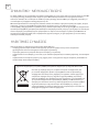
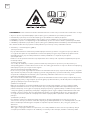
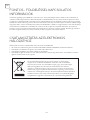
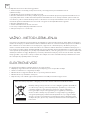
Important information for correct disposal of the product in accordance with EC Directive
2012/19/EU.
At the end of its working life, the product must not be disposed of as
urban waste. It must be taken to a special local authority differentiated
waste collection centre or to a dealer providing this service. Disposing of a
household appliance separately avoids possible negative consequences
for the environment and health deriving from inappropriate disposal and
enables the constituent materials to be recovered to obtain significant
savings in energy and resources. As a reminder of the need to dispose of
household appliances separately, the product is marked with a crossed-out
wheeled dustbin.
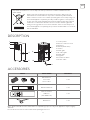
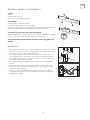
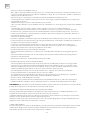
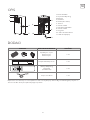
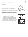
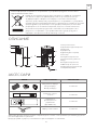
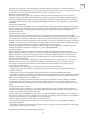
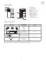
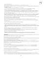
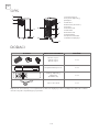
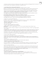
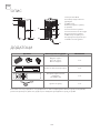
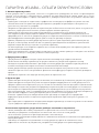
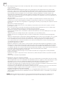
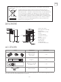
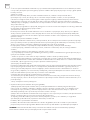
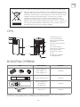
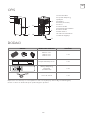
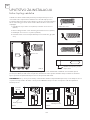
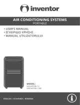
DESCRIPTION
ACCESSORIES
1. Control panel
2. Remote control receiver
3. Deflector
4. Handle (both sides)
5. Castors
6. Intake grille
7. Air outlet grille
8. Intake grille
9. Plug fixer
10. Condenser drain
11. Power cable
PARTS PARTS NAME QUANTITY
Exhaust hose
Hose inlet
Hose outlet
1 set
Window slider kit 1 set
Remote Control
Batteries
(Two AAA 1.5V)
1 set
Drain Hose 1 set
Note: All the illustrations in this manual are for explanatory purposes only. Your appliance may be slightly
different.
Be sure all accessories are removed from the packing before use.
1
2
3
4
5
6
7
9
8
10
11

12
ENG
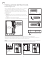
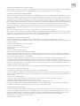
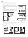
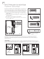
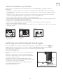
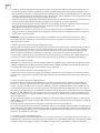
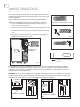
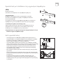
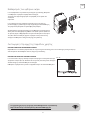
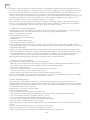
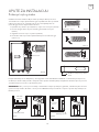
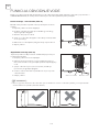
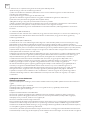
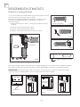
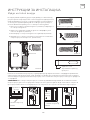
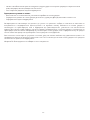
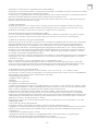
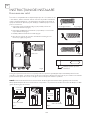
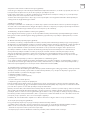
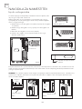
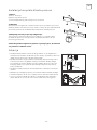
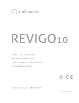
INSTALLATION INSTRUCTIONS
Exhausting hot air
In the Cool Mode the appliance must be placed close to a window or
opening so that the warm exhaust air can be ducted outside.
First position unit on a flat floor and make sure there’s a minimum
of 18”(45cm) clearance around the unit, and is within the vicinity of a
single circuit outlet
power source.
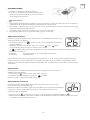
1. Extend either side of the hose (Fig.1)and screw the hose inlet
(Fig.2).
2. Extend the other side of the hose and screw it to the hose outlet
(Fig.3).
3. Install the hose inlet into the unit (Fig.4).
4. Affix the hose outlet into the window slider kit and seal. (Fig.5 & 6).
Your window slider kit has been designed to fit most standard vertical and horizontal window
applications,however, it may be necessary for you to modify some aspects of the installation procedures for
certain types of windows. The window slider kit can be fastened with screws.
NOTE: If the window opening is less than the minimum length of the window slider kit, cut the end without the
hold in it short enough to fit in the window opening. Never cut out the hole in window slider kit.
Extend the hose Fig.1
Fig. 2
Fig. 3
Cut on opposite side of hole
Fig. 4
Slide into
Vertical
Window
Horizontal
Window
Window Slider
Window Slider
Fig. 5 Fig. 6

13
ENG
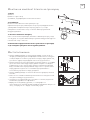
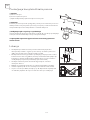
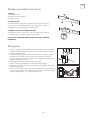
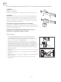
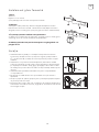
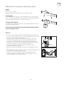
Window slider kit installation
Location
1:Parts:
A) Panel
B) Panel with one hole
C) Screw to lock window kit in place
2: Assembly:
Slide Panel B into Panel A and size
to widow width. Windows sizes vary. When
sizing the window width, be sure that the window kit assembly is free from
gaps from gaps and/or air pockets when taking measurements.
3. Lock the screw into the holes that correspond
With the width that your window requires to ensure that there are no gaps
or air pockets in the window kit assembly after installation.
4. Use the provided foam window kit sealer to close any gaps or air
pockets.
• The unit should be placed on a firm foundation to minimize noise and
vibration. For safe and secure positioning. place the unit on a smooth,
level floor strong enough to support the unit.
• The unit has casters to aid placement, but it should only be rolled on
smooth, flat surfaces. Use caution when rolling on carpeted surfaces.
Use caution and Protect floors when rolling over wood floors. Do not
attempt to roll the unit over objects.
• The unit must be placed within reach of a properly rated grounded
socket.
• Never place any obstacles around the air inlet or outlet of the unit.
• Allow at least 18”(45cm) of around and above space away from the
wall for efficient working.
• The hose can be extended, but it is the best to keep the length to
minimum required. Also make sure that the hose does not have any
sharp bends or sags.
45 cm
45cm
45cm

14
ENG
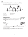
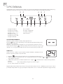
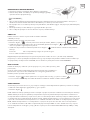
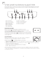
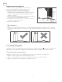
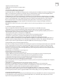
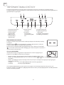
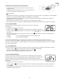
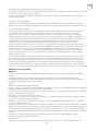
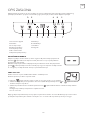
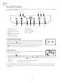
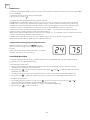
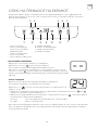
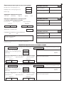
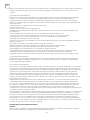
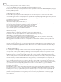
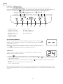
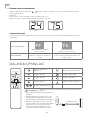
DESCRIPTION OF THE DISPLAY SCREEN
TURNING THE APPLIANCE ON
COOL mode
Plug into the mains socket, then the appliance is standby.
Press the button to make the appliance turn on. The last function active when it
was turned off will appear.
Never turn the air conditioner off by unplugging from the mains. Always press
the button , then wait for a few minutes before unplugging. This allows the
appliance to perform a cycle of checks to verify operation.
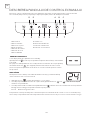
Ideal for hot muggy weather when you need to cooling and dehumidify the room.
To set this mode correctly:
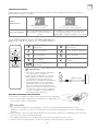
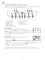
1. Timer button
2. Fan button
3. Increase button
4. Display screen
5. Decrease button
6. Mode button
7. ON/OFF button
A. Cool symbol
B. Dehumidify symbol
C. Fan symbol
D. Timer symbol
The control panel is on the top of the appliance, enables you to manage part functions without remote
controller, but to fully exploit its potential, you must use the remote controller.
1 2 3 4 5 6 7
A B CD E
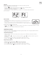
• Press the “ ” button a number of times until the “Cool” symbol light appears.
• Select the target temperature 18°C-32°C (64°F-90°F) by pressing the or button until the corresponding
value is displayed.
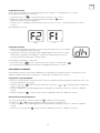
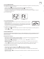
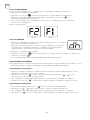
• Select the required fan speed by pressing the “ ” button. Different fan speed have different function.
F2 High To achieved the temperature as fast as possible.
F1 Low Run of the low noise.
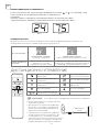
The most suitable temperature for the room during the summer varies from 24°C to 27°C. You are
recommended, however, not to set a temperature much below the outdoor temperature. This will cause
unnecessary power consumption.

15
ENG
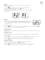
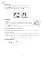
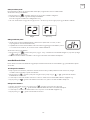
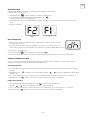
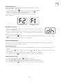
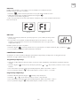
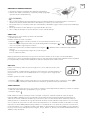
FAN mode
DRY mode
When using the appliance in this mode, the air hose does not need to be attached.
To set this mode correctly:
• Press the “ ” button a number of times until the “ Fan ” symbol appears.
• Select the required fan speed by pressing the “ ” button.
Two speeds are available: High/Low
• If appear “ F2 ”symbol standard for high speed fan, and “ F1 ” stand for low speed fan.
As the figure below:
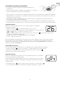
• Ideal to reduce room humidity (spring and autumn, damp rooms rainy periods, etc).
• Before using the dry mode, the appliance should be prepared in the same way
as for cool mode, with the air exhaust hose attached to enable the moisture to be
discharged outside.
To set this mode correctly:
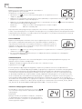
• Press the “ ” button a number of times until the “ Dry ”symbol light appears, the screen will appear ” ”
• In this mode, fan speed is selected automatically by the appliance.
High Low
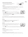
SETTING THE TIMER
Programming start-up
Programming shut down
This timer can be used to delay the appliance start up or shutdown, this avoids wasting electricity by optimizing
operating periods.
• Turn on the appliance, choose the mode you want, for example Dehumidify mode, high fan speed. Turn off
the appliance.
• Press the “ “ button , the screen starts to flash, press the “ “ / “ “ to adjust the set time from 0.5-24
hours.
• In 5 seconds without the operation, the timer start function, then the “Timer” symbol lights.
• Press the “ “ button again to cancel the Timer, and the “Timer” symbol disappear.
• When the appliance is running, press the “ ” button, the screen starts to flash.
• Press the “ “ / “ “ to adjust the set time from 0.5-24 hours.
• In 5 seconds without the operation, the timer start function, then the “ Timer” symbol lights.
• Press the “ “ button again to cancel the Timer, and the “ Timer “ symbol disappear.

16
ENG
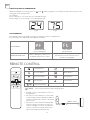
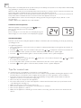
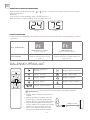
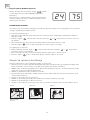
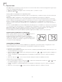
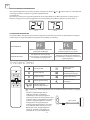
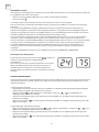
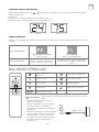
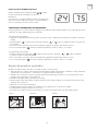
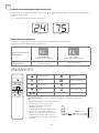
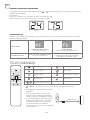
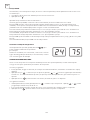
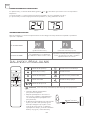
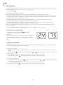
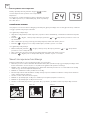
SWITCH THE UNIT OF TEMPERATURE
When the appliance is running, hold on “ ” and” ” button together 3 seconds by the same time, then you can
change the unit of temperature.
For example:
Before change, in cool mode, the screen display like fig1.
After change, in cool mode, the screen display like fig2.
Fig. 1 Fig. 2
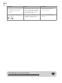
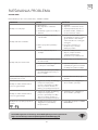
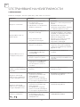
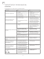
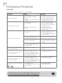
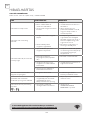
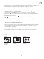
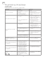
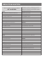
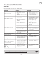
SELF-DIAGNOSIS
The appliance has a self diagnosis system to identify a number of malfunctions.
Error messages are displayed on the appliance display.
IF DISPLAYED
PROBE FAILURE
(sensor damaged)
FULL TANK
(safety tank full)
WHAT SHOULD I DO? If this is displayed, contact your
local authorized service centre
Empty the internal safety tank, following
the instructions in the “End of season
operations” paragraph.
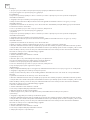
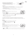
On/Off button Fan speed button
Increase button Mode button
Decrease button Swing button
Timer button Sleep button
Unit Switch button
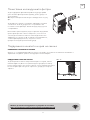
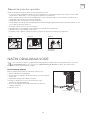
REMOTE CONTROL
• Point the remote control at the receiver on
the appliance.
• The remote control must be no more than
7 meters away from the appliance (without
obstacles between the remote control and
the receiver).
• The remote control must be handled with
extreme care. Do not drop it or expose it
to direct sunlight or sources of heat. If the
remote control do not work, please try to
take out the battery, and put it back.
MAX 7 meters
NOTE This serial model has no auto swing function.

17
ENG
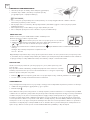
INSERTING OR REPLACING THE BATTERIES
• Remove the cover on the rear of the remote control;
• Insert two “AAA” 1.5V batteries in the correct position (see
instructions inside the battery compartment);
• If the remote control unit is replaced or disposed of, the batteries must be removed and discarded in
accordance with current legislation as they are harmful to the environment.
• Do not mix old and new batteries. Do not mix alkaline, standard (carbon-zinc) or rechargeable (nickel-
cadmium) batteries.
• Do not dispose of batteries in fire. Batteries may explode or leak.
• If the remote control is not be used for a certain length of time, remove the batteries.
NOTE
COOL mode
Ideal for hot muggy weather when you need to cooling and dehumidify the room.
To set this mode correctly:
• Press the “ ” button a number of times until the “Cool” symbol light appears.
• Select the target temperature 18ºC-32ºC (64ºF-90ºF) by pressing the or button
until the corresponding value is displayed.
• Select the required fan speed by pressing the “ ” button. Different fan speed have different function.
F2 High To achieved the temperature as fast as possible.
F1 Low Run of the low noise.
The most suitable temperature for the room during the summer varies from 24ºC to 27ºC (75ºF to 81ºF ). You
are recommended, however, not to set a temperature much below the outdoor temperature. The fan speed
difference is more noticeable when the appliance is under FAN mode but may not be noticeable under COOL
mode.
FAN mode
When using the appliance in this mode, the air hose does not need to be attached.
• Press the button a number of times until the “Fan” symbol appears.
• Select the required fan speed by pressing the button.
Two speeds are available: High / Low.
DRY mode
• Press the “ ” button a number of times until the “Dry”symbol light appears, the screen will appear “ ”
• In this mode, fan speed is selected automatically by the appliance and default low speed fan.
Ideal to reduce room humidity (spring and autumn, damp rooms rainy periods, etc).
In dry mode, the appliance should be prepared in the same way as for cool mode, with
the air exhaust hose attached to enable the moisture to be discharged outside.
To set this mode correctly:
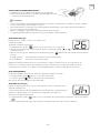
SLEEP function
This function is useful for the night as it gradually reduces operation of the appliance.
To set this function correctly:
• Select the cool or heat mode as described above.
• Press the button.
The appliance operates in the previously selected mode.
When you choose the sleep function, the screen will reduce the brightness, and the fan speed is low.
The SLEEP function maintains the room at optimum temperature without excessive fluctuations in either

18
ENG
Switch the unit of temperature
When the appliance is running, press the button,
then you can change the unit of temperature.
For example:
Before change, in cool mode, the screen display like fig left.
After change, in cool mode, the screen display like fig right.
SETTING THE TIMER
This timer can be used to delay the appliance startup or shutdown, this avoids wasting electricity by optimising
operating periods.
* Programming start up
• Turn on the appliance, choose the mode you want, for example Dehumidify mode, high fan speed. Turn off
the appliance.
• Press the “ “ button , the screen starts to flash, press the or to adjust the set time from 0.5-24 hours.
• In 5 seconds without the operation, the timer start function, then the “Timer” symbol lights.
• Press the “ “ button button again to cancel the Timer, and the “Timer” symbol disappear.
* Programming shut down
• When the appliance is running, press the “ ” button, the screen starts to flash,press the or to adjust
the set time from 0.5-24 hours.
• In 5 seconds without the operation, the timer start function, then the “ Timer” symbol lights.
• Press the “ “ button again to cancel the Timer, and the “ Timer “ symbol disappear.
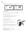
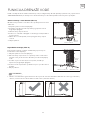
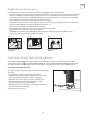
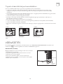
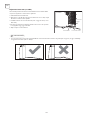
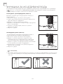
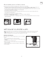
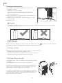
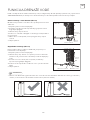
To get the best from your appliance, follow these recommendations:
• Close the windows and doors in the room to be air conditioned (Fig. 9).When installing the appliance semi-
permanently, you should leave a door slightly open (as little as 1 cm) to guarantee correct ventilation;
• Protect the room from direct exposure to the sun by partially closing curtains and/or blinds to make the
appliance much more economical to run (Fig. 10);
• Never rest objects of any kind on the appliance;
• Do not block the air inlet or outlet of the appliance. Reduced air flow will result in poor performance and
could damage the unit (Fig. 11).
• Make sure there are no heat sources in the room;
• Never use the appliance in very damp rooms (laundries for example).
• Never use the appliance outdoors.
• Make sure the appliance is standing on a level surface. If necessary, place the castor locks under the front
wheels.
Tips for correct use
temperature or humidity with silent operation. Fan speed is always at Low, while room temperature and humidity
vary gradually to ensure the most comfortable.
When in COOL mode, the selected temperature will increase by 1ºC (1ºF) per hour in a 2 hour period. This new
temperature will be maintained for the next 6 hours. Then the appliance turn it off.
When in HEAT mode, the selected temperature will decrease by 1ºC (1ºF) per hour in a 3 hour period. This new
temperature will be maintained for the next 5 hours. Then the appliance turn it off.
The SLEEP function can be canceled at any time during operation by pressing the “Sleep”, “Mode” or “fan
speed” button.
In FAN or DRY mode, SLEEP function is still available.

19
ENG
Fig. 9 Fig. 10 Fig. 11
Close doors and
windows Close curtains Do not cover the
appliance
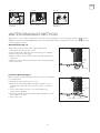
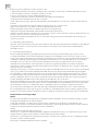
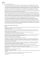
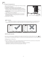
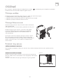
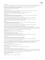
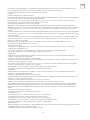
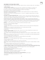
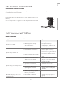
WATER DRAINAGE METHOD
When there is excess water condensation inside the unit, the appliance stops running and shows “ ” (FULL
TANK as mentioned in SELF-DIAGNOSIS). This indicates that the water condensation needs to be drained using
the following procedures:
Water may need to be drained in high humidity areas
1 .Unplug the unit from power source.
2. Place a drain pan under the lower drain plug. See diagram.
3. Remove the lower drain plug.
4. Water will drain out and collect in the drain pan (maybe not
supplied ).
5. After the water is drained, replace the lower drain plug firmly.
6. Turn on the unit.
Manual Draining (Fig.12)
Fig. 12
Drain
outlet
Drain cap
Drain pan
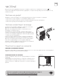
While using the unit in dehumidifier mode, continuous drainage
is recommended.
1. Unplug the unit from the power source.
2. Remove the drain plug. While doing this operation some
residual water may spill so please have a pan to collect the
water.
3. Connect the drain hose (1/2” or 12.7mm, maybe not
supplied). See diagram.
4. The water can be continuously drained through the hose into
a floor drain or bucket.
5. Turn on the unit.
Continuous Draining (Fig.13)
Fig. 13
Drain outlet
Drain cap
Drain hose

20
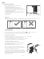
ENG
• Please be sure that the height of and section of the drain hose should not be higher than that of the drain
outlet, or the water tank may not be drained. (Fig. 14 and Fig.15)
NOTE
Fig. 14 Fig. 15
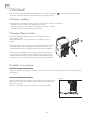
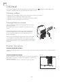
CLEANING
Cleaning the cabinet
Before cleaning or maintenance, turn the appliance off by pressing the button on the control panel or
remote control, wait for a few minutes then unplug from the mains socket.
You should clean the appliance with a slightly damp cloth then dry with a dry cloth.
• Never wash the appliance with water. It could be dangerous.
• Never use petrol, alcohol or solvents to clean the appliance.
• Never spray insecticide liquids or similar.
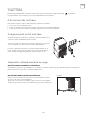
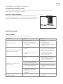
Cleaning the air filters
Start-end of season operations
START OF SEASON CHECKS
To keep your appliance working efficiently, you should clean the
filter every week of operation.
The evaporator filter can take out like below Fig.
To avoid possible cuts, avoid contacting the metal parts of the
appliance when removing or re-installing the filter. It can result in
the risk of personal injury.
Use a vacuum cleaner to remove dust accumulations from the
filter. If it is very dirty, immerse in warm water and rinse a number
of times. The water should never be hotter than 40ºC (104ºF).
After washing, leave the filter to dry then attach the intake grille to
the appliance.
Make sure the power cable and plug are undamaged and the earth system is efficient.
Follow the installation instructions precisely
Pagina se încarcă...
Pagina se încarcă...
Pagina se încarcă...
Pagina se încarcă...
Pagina se încarcă...
Pagina se încarcă...
Pagina se încarcă...
Pagina se încarcă...
Pagina se încarcă...
Pagina se încarcă...
Pagina se încarcă...
Pagina se încarcă...
Pagina se încarcă...
Pagina se încarcă...
Pagina se încarcă...
Pagina se încarcă...
Pagina se încarcă...
Pagina se încarcă...
Pagina se încarcă...
Pagina se încarcă...
Pagina se încarcă...
Pagina se încarcă...
Pagina se încarcă...
Pagina se încarcă...
Pagina se încarcă...
Pagina se încarcă...
Pagina se încarcă...
Pagina se încarcă...
Pagina se încarcă...
Pagina se încarcă...
Pagina se încarcă...
Pagina se încarcă...
Pagina se încarcă...
Pagina se încarcă...
Pagina se încarcă...
Pagina se încarcă...
Pagina se încarcă...
Pagina se încarcă...
Pagina se încarcă...
Pagina se încarcă...
Pagina se încarcă...
Pagina se încarcă...
Pagina se încarcă...
Pagina se încarcă...
Pagina se încarcă...
Pagina se încarcă...
Pagina se încarcă...
Pagina se încarcă...
Pagina se încarcă...
Pagina se încarcă...
Pagina se încarcă...
Pagina se încarcă...
Pagina se încarcă...
Pagina se încarcă...
Pagina se încarcă...
Pagina se încarcă...
Pagina se încarcă...
Pagina se încarcă...
Pagina se încarcă...
Pagina se încarcă...
Pagina se încarcă...
Pagina se încarcă...
Pagina se încarcă...
Pagina se încarcă...
Pagina se încarcă...
Pagina se încarcă...
Pagina se încarcă...
Pagina se încarcă...
Pagina se încarcă...
Pagina se încarcă...
Pagina se încarcă...
Pagina se încarcă...
Pagina se încarcă...
Pagina se încarcă...
Pagina se încarcă...
Pagina se încarcă...
Pagina se încarcă...
Pagina se încarcă...
Pagina se încarcă...
Pagina se încarcă...
Pagina se încarcă...
Pagina se încarcă...
Pagina se încarcă...
Pagina se încarcă...
Pagina se încarcă...
Pagina se încarcă...
Pagina se încarcă...
Pagina se încarcă...
Pagina se încarcă...
Pagina se încarcă...
Pagina se încarcă...
Pagina se încarcă...
Pagina se încarcă...
Pagina se încarcă...
Pagina se încarcă...
Pagina se încarcă...
Pagina se încarcă...
Pagina se încarcă...
Pagina se încarcă...
Pagina se încarcă...
Pagina se încarcă...
Pagina se încarcă...
Pagina se încarcă...
Pagina se încarcă...
Pagina se încarcă...
Pagina se încarcă...
Pagina se încarcă...
Pagina se încarcă...
Pagina se încarcă...
Pagina se încarcă...
Pagina se încarcă...
Pagina se încarcă...
Pagina se încarcă...
Pagina se încarcă...
Pagina se încarcă...
Pagina se încarcă...
Pagina se încarcă...
Pagina se încarcă...
Pagina se încarcă...
Pagina se încarcă...
Pagina se încarcă...
Pagina se încarcă...
Pagina se încarcă...
Pagina se încarcă...
Pagina se încarcă...
Pagina se încarcă...
Pagina se încarcă...
Pagina se încarcă...
Pagina se încarcă...
Pagina se încarcă...
Pagina se încarcă...
Pagina se încarcă...
Pagina se încarcă...
Pagina se încarcă...
Pagina se încarcă...
Pagina se încarcă...
Pagina se încarcă...
Pagina se încarcă...
Pagina se încarcă...
Pagina se încarcă...
Pagina se încarcă...
Pagina se încarcă...
Pagina se încarcă...
Pagina se încarcă...
Pagina se încarcă...
Pagina se încarcă...
Pagina se încarcă...
Pagina se încarcă...
Pagina se încarcă...
Pagina se încarcă...
Pagina se încarcă...
Pagina se încarcă...
Pagina se încarcă...
Pagina se încarcă...
Pagina se încarcă...
Pagina se încarcă...
Pagina se încarcă...
Pagina se încarcă...
Pagina se încarcă...
Pagina se încarcă...
Pagina se încarcă...
Pagina se încarcă...
Pagina se încarcă...
Pagina se încarcă...
Pagina se încarcă...
Pagina se încarcă...
Pagina se încarcă...
Pagina se încarcă...
Pagina se încarcă...
Pagina se încarcă...
Pagina se încarcă...
Pagina se încarcă...
Pagina se încarcă...
Pagina se încarcă...
Pagina se încarcă...
Pagina se încarcă...
Pagina se încarcă...
Pagina se încarcă...
Pagina se încarcă...
Pagina se încarcă...
Pagina se încarcă...
Pagina se încarcă...
Pagina se încarcă...
Pagina se încarcă...
Pagina se încarcă...
Pagina se încarcă...
Pagina se încarcă...
Pagina se încarcă...
Pagina se încarcă...
Pagina se încarcă...
Pagina se încarcă...
Pagina se încarcă...
Pagina se încarcă...
Pagina se încarcă...
Pagina se încarcă...
Pagina se încarcă...
Pagina se încarcă...
Pagina se încarcă...
Pagina se încarcă...
Pagina se încarcă...
Pagina se încarcă...
Pagina se încarcă...
Pagina se încarcă...
Pagina se încarcă...
Pagina se încarcă...
Pagina se încarcă...
Pagina se încarcă...
Pagina se încarcă...
Pagina se încarcă...
Pagina se încarcă...
Pagina se încarcă...
Pagina se încarcă...
Pagina se încarcă...
Pagina se încarcă...
Pagina se încarcă...
Pagina se încarcă...
Pagina se încarcă...
Pagina se încarcă...
Pagina se încarcă...
Pagina se încarcă...
Pagina se încarcă...
Pagina se încarcă...
Pagina se încarcă...
Pagina se încarcă...
Pagina se încarcă...
Pagina se încarcă...
-
 1
1
-
 2
2
-
 3
3
-
 4
4
-
 5
5
-
 6
6
-
 7
7
-
 8
8
-
 9
9
-
 10
10
-
 11
11
-
 12
12
-
 13
13
-
 14
14
-
 15
15
-
 16
16
-
 17
17
-
 18
18
-
 19
19
-
 20
20
-
 21
21
-
 22
22
-
 23
23
-
 24
24
-
 25
25
-
 26
26
-
 27
27
-
 28
28
-
 29
29
-
 30
30
-
 31
31
-
 32
32
-
 33
33
-
 34
34
-
 35
35
-
 36
36
-
 37
37
-
 38
38
-
 39
39
-
 40
40
-
 41
41
-
 42
42
-
 43
43
-
 44
44
-
 45
45
-
 46
46
-
 47
47
-
 48
48
-
 49
49
-
 50
50
-
 51
51
-
 52
52
-
 53
53
-
 54
54
-
 55
55
-
 56
56
-
 57
57
-
 58
58
-
 59
59
-
 60
60
-
 61
61
-
 62
62
-
 63
63
-
 64
64
-
 65
65
-
 66
66
-
 67
67
-
 68
68
-
 69
69
-
 70
70
-
 71
71
-
 72
72
-
 73
73
-
 74
74
-
 75
75
-
 76
76
-
 77
77
-
 78
78
-
 79
79
-
 80
80
-
 81
81
-
 82
82
-
 83
83
-
 84
84
-
 85
85
-
 86
86
-
 87
87
-
 88
88
-
 89
89
-
 90
90
-
 91
91
-
 92
92
-
 93
93
-
 94
94
-
 95
95
-
 96
96
-
 97
97
-
 98
98
-
 99
99
-
 100
100
-
 101
101
-
 102
102
-
 103
103
-
 104
104
-
 105
105
-
 106
106
-
 107
107
-
 108
108
-
 109
109
-
 110
110
-
 111
111
-
 112
112
-
 113
113
-
 114
114
-
 115
115
-
 116
116
-
 117
117
-
 118
118
-
 119
119
-
 120
120
-
 121
121
-
 122
122
-
 123
123
-
 124
124
-
 125
125
-
 126
126
-
 127
127
-
 128
128
-
 129
129
-
 130
130
-
 131
131
-
 132
132
-
 133
133
-
 134
134
-
 135
135
-
 136
136
-
 137
137
-
 138
138
-
 139
139
-
 140
140
-
 141
141
-
 142
142
-
 143
143
-
 144
144
-
 145
145
-
 146
146
-
 147
147
-
 148
148
-
 149
149
-
 150
150
-
 151
151
-
 152
152
-
 153
153
-
 154
154
-
 155
155
-
 156
156
-
 157
157
-
 158
158
-
 159
159
-
 160
160
-
 161
161
-
 162
162
-
 163
163
-
 164
164
-
 165
165
-
 166
166
-
 167
167
-
 168
168
-
 169
169
-
 170
170
-
 171
171
-
 172
172
-
 173
173
-
 174
174
-
 175
175
-
 176
176
-
 177
177
-
 178
178
-
 179
179
-
 180
180
-
 181
181
-
 182
182
-
 183
183
-
 184
184
-
 185
185
-
 186
186
-
 187
187
-
 188
188
-
 189
189
-
 190
190
-
 191
191
-
 192
192
-
 193
193
-
 194
194
-
 195
195
-
 196
196
-
 197
197
-
 198
198
-
 199
199
-
 200
200
-
 201
201
-
 202
202
-
 203
203
-
 204
204
-
 205
205
-
 206
206
-
 207
207
-
 208
208
-
 209
209
-
 210
210
-
 211
211
-
 212
212
-
 213
213
-
 214
214
-
 215
215
-
 216
216
-
 217
217
-
 218
218
-
 219
219
-
 220
220
-
 221
221
-
 222
222
-
 223
223
-
 224
224
-
 225
225
-
 226
226
-
 227
227
-
 228
228
-
 229
229
-
 230
230
-
 231
231
-
 232
232
-
 233
233
-
 234
234
-
 235
235
-
 236
236
-
 237
237
-
 238
238
-
 239
239
-
 240
240
-
 241
241
-
 242
242
-
 243
243
-
 244
244
-
 245
245
-
 246
246


Lucrări înrudite
Alte documente
-
Taurus Alpatec DH 1201 Manualul proprietarului
-
-
-
-
-
-
Gorenje D16M Manualul proprietarului
-
 Inventor M3GHP290-12 Portable Air Conditioning Systems Manual de utilizare
-
 turbionaire REVIGO10 Mobile Air Conditioner Manual de utilizare
-
SOMOGYI ELEKTRONICS ACH 12000 Manual de utilizare

