
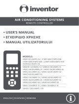
SPLIT-TYPE
AIR CONDITIONER
USER MANUAL
For R32 DC Inverter models:
TM36AF21-1232IA
TM36AF21-1232IAW
TM36I13-1232IAWUV
TM52AF21-1832IAW
TM53I13-1832IAWUV
TM70AF21-2432IAW
MKD
BIH/
MNE
RO SLO SRBENG BG GR HR
Ver. 2021

OPERATING INSTRUCTION
Note: All the pictures in this manual are just schematic diagrams, the actual is the standard. Please read
this owner’s manual carefully and thoroughly before operating the unit! Take care of this manual for future
reference.
UPUTE ZA UPOTREBU
Napomena: Sve slike u ovom priručniku su samo shematski dijagrami, fizički proizvod je standard. Molimo
Vas da pažljivo i temeljito pročitate ovo uputstvo za upotrebu prije korištenja uređaja! Čuvajte ovaj priručnik
za buduće korištenje.
ΕΓΧΕΙΡΙΔΙΟ ΧΡΉΣΉΣ
Σημείωση: Οι εικόνες στο παρόν εγχειρίδιο είναι σχεδιαγράμματα, ανατρέξτε στο πραγματικό προϊόν. Διαβάστε
προσεκτικά τις προφυλάξεις στο παρόν εγχειρίδιο προτού θέσετε τη μονάδα σε λειτουργία! Φυλάξτε το παρόν
εγχειρίδιο για μελλοντική χρήση.
ИНСТРУКЦИЯ ЗА УПОТРЕБА
Забележка: Всички снимки в тази инструкция са само схематични диаграми, действителните са
стандартните. Моля, прочетете внимателно тази инструкция за употреба преди да започнете работа с
уреда! Запазете тази инструкция за бъдещи справки
PRIROČNIK ZA UPORABO
Opomba: Vse slike v tem priročniku so le shematske risbe, dejansko stanje je standard. Prosimo, da pred
uporabo skrbno in temeljito preberete ta priročnik za uporabo! Priročnik shranite za kasnejšo uporabo.
MANUAL DE UTILIZARE
Nota: Fotografiile din acest manual sunt doar diagrame schematice. Vă rugăm să citiți “Manualul de Utilizare”
cu atenție, înainte de a utiliza aerul condiționat, pentru a asigura funcționarea corespunzătoare. Păstrați
manualul pentru referințe ulterioare.
ENG
HR
GR
BG
UPUTSTVO ZA UPOTREBU
Napomena: Sve slike u ovom priručniku su samo šematski dijagrami, fizički proizvod je standard. Molimo Vas
da pažljivo i temeljno pročitate ovo uputstvo za upotrebu prije korišćenja uređaja! Sačuvajte ovo uputstvo za
buduću upotrebu.
BIH/
MNE
SLO
RO
УПАТСТВО ЗА УПОТРЕБА
Напомена: Сите слики во овој прирачник се само шематски дијаграми, физичкиот производ е
стандард. Ве молиме внимателно и теменлно да го причитате ова упатство за употреба пред
користење на уредот! Сочувајте го ова упатство за идна употреба.
MKD
UPUTSTVO ZA UPOTREBU
Napomena: Sve slike u ovom priručniku su samo šematski dijagrami, fizički proizvod je standard. Molimo
Vas da pažljivo i temeljno pročitate ovo uputstvo za upotrebu pre korišćenja uređaja! Sačuvajte ovo
uputstvo za buduću upotrebu.
SRB

3
ENG
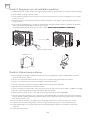
• Read this guide before installing and using the appliance.
• During the installation of the indoor and outdoor units the access to the working area should be forbidden to
children. Unforeseeable accidents could happen.
• Make sure that the base of the outdoor unit is firmly fixed.
• Check that air cannot enter the refrigerant system and check for refrigerant leaks when moving the air
conditioner.
• Carry out a test cycle after installing the air conditioner and record the operating data.
• Protect the indoor unit with a fuse of suitable capacity for the maximum input current or with another overload
protection device.
• Ensure that the mains voltage corresponds to that stamped on the rating plate. Keep the switch or power plug
clean. Insert the power plug correctly and firmly into the socket, thereby avoiding the risk of electric shock or
fire due to insufficient contact.
• Check that the socket is suitable for the plug , otherwise have the socket changed.
• The appliance must be fitted with means for disconnection from the supply mains having a contact separation
in all poles that provide full disconnection under overvoltage category III conditions, and these means must be
incorporated in the fixed wiring in accordance with the wiring rules.
• The air conditioner must be installed by professional or qualified persons.
• Do not install the appliance at a distance of less than 50 cm from inflammable substances (alcohol, etc.) or from
pressurised containers (e.g. spray cans).
• If the appliance is used in areas without the possibility of ventilation, precautions must be taken to prevent any
leaks of refrigerant gas from remaining in the environment and creating a danger of fire
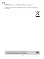
• The packaging materials are recyclable and should be disposed of in the separate waste bins .Take the air
conditioner at the end of its useful life to a special waste collection centre for disposal.
• Only use the air conditioner as instructed in this booklet. These instructions are not intended to cover every
possible condition and situation . As with any electrical household appliance , common sense and caution are
therefore always recommended for installation, operation and maintenance.
• The appliance must be installed in accordance with applicable national regulations.
• Before accessing the terminals , all the power circuits must be disconnected from the power supply.
• The appliance shall be installed in accordance with national wiring regulations.
• This appliance can be used by children aaged from 8 years and above and persons with reduced physical,
sensory or mental capabilities or lack of experience and knowledge if they have been given supervision or
instruction concerning use of the appliance in a safe way and understand the hazards involved. Children shall
not play with the appliance. Cleaning and user maintenance shall not be made by children without supervision.
• Do not try to install the conditioner alone; always contact specialized technical personnel.
• Cleaning and maintenance must be carried out by specialized technical personnel. In any case disconnect the
appliance from the mains electricity supply before carrying out any cleaning or maintenance.
• Ensure that the mains voltage corresponds to that stamped on the rating plate. Keep the switch or power plug
clean. Insert the power plug correctly and firmly into the socket , thereby avoiding the risk of electric shock or
fire due to insufficient contact.
• Do not pull out the plug to switch off the appliance when it is in operation, since this could create a spark and
cause a fire, etc.
• This appliance has been made for air conditioning domestic environments and must not be used for any other
purpose , such as for drying clothes, cooling food, etc.
• Always use the appliance with the air filter mounted . The use of the conditioner without air filter could cause an
excessive accumulation of dust or waste on the inner parts of the device with possible subsequent failures.
• The user is responsible for having the appliance installed by a qualified technician , who must check that it is
earthed in accordance with current legislation and insert a thermomagnetic circuit breaker.
• The batteries in remote controller must be recycled or disposed of properly. Disposal of Scrap Batteries ---
Please discard the batteries as sorted municipal waste at the accessible collection point.
• Never remain directly exposed to the flow of cold air for a long time. The direct and prolonged exposition
SAFETY RULES AND RECOMMENDATIONS
FOR THE INSTALLER
SAFETY PRECAUTIONS

4
ENG
to cold air could be dangerous for your health .Particular care should be taken in the rooms where there are
children , old or sick people.
• If the appliance gives off smoke or there is a smell of burning, immediately cut off the pow er supply and contact
the Service Centre.
• The prolonged use of the device in such conditions could cause fire or electrocution.
• Have repairs carried out only by an authorised Service Centre of the manufacturer . Incorrect repair could
expose the user to the risk of electric shock, etc.
• Unhook the automatic switch if you foresee not to use the device for a long time. The airflow direction must be
properly adjusted.
• Only use the air conditioner as instructed in this booklet. These instructions are not intended to cover every
possible condition and situation. As with any electrical household appliance, common sense and caution are
therefore always recommended for installation , operation and maintenance.
• Ensure that the appliance is disconnected from the power supply when it will remain inoperative for a long
period and before carrying out any cleaning or maintenance.
• Selecting the most suitable temperature can prevent damage to the appliance.
• Do not bend, tug or compress the power cord since this could damage it. Electrical shocks or fire are probably
due to a damaged power cord. Specialized technical personnel only must replace a damaged power cord.
• Do not use extensions or gang modules.
• Do not touch the appliance when barefoot or parts of the body are wet or damp.
• Do not obstruct the air inlet or outlet of the indoor or the outdoor unit. The obstruction of these openings
causes a reduction in the operative efficiency of the conditioner with possible consequent failures or damages.
• In no way alter the characteristics of the appliance.
• Do not install the appliance in environments where the air could contain gas , oil or sulphur or near sources of
heat.
• This appliance is not intended for use by persons (including children ) with reduced physical, sensory or mental
capabilities, or lack of experience and knowledge, unless they have been given supervision or instruction
concerning use of the appliance by a person responsible for their safety.
• Do not climb onto or place any heavy or hot objects on top of the appliance.
• Do not leave windows or doors open for long when the air conditioner is operating.
• Do not direct the airflow onto plants or animals.
• A long direct exposition to the flow of cold air of the conditioner could have negative effects on plants and
animals.
• Do not put the conditioner in contact with water. The electrical insulation could be damaged and thus causing
electrocution.
• Do not climb onto or place any objects on the outdoor unit
• Never insert a stick or similar object into the appliance. It could cause injury.
• Children should be supervised to ensure that they do not play with the appliance. If the supply cord is damaged,
it must be replaced by the manufacturer,its service agent or similarly qualified persons in order to avoid a
hazard.
SAFETY RULES AND PROHIBITIONS

5
ENG
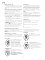
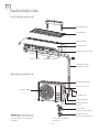
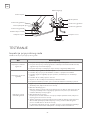
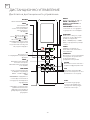
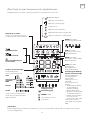
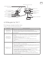
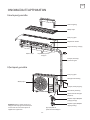
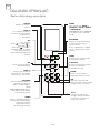
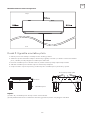
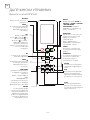
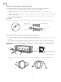
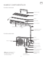
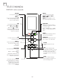
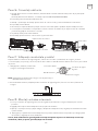
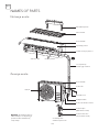
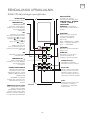
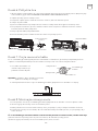
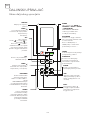
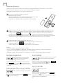
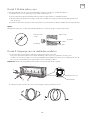
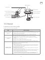
NAMES OF PARTS
Indoor unit
Outdoor unit
Note: This figure shown may be
different from the actual object.
Please take the latter as the
standard.
Mounting plate
Air filter
Air inlet
Front panel
Emergency button
Refrigerant
connecting pipe
Air inlet
Air outlet
Air outlet Air deflector and flap
Wiring cover
Drainage pipe
Connection wiring
Valve protective cover
Gas valve
(Low pressure valve)
Liquid valve
(High pressure valve)
With the protective
cover removed

6
ENG
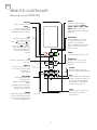
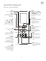
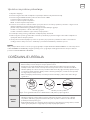
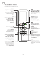
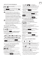
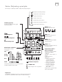
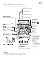
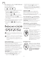
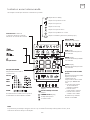
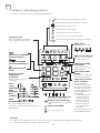
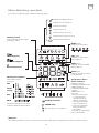
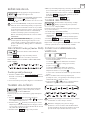
REMOTE CONTROLLER
Remote control DISPLAY
ON/OFF
Turns the unit on or off.
MODE
Scrolls through operation
modes as follows: AUTO ->
COOL -> DRY-> HEAT ->FAN
NOTE: HEAT mode is not
supported by the cooling only
appliance.
ECO/GEAR
Press this button to enter the
energy efficient mode in a
sequence of following:
ECO -> GEAR (75%) -> GEAR
(50%) -> Previous setting
mode -> ECO ......
OK
Used to confirm the selected
functions
TIMER
Set timer to turn unit on or off
SHORTCUT
Used to restore the current
settings or resume previous
settings.
CLEAN
Used to start/stop the Self
Clean or Active Clean function.
LED
Turns indoor unit’s LED display
and air conditioner buzzer on
and off (model dependent),
which create a comfortable
and quiet environment.
Turbo
Enables unit to reach preset
temperature in shortest
possible time
TEMP
Increases temperate in
1°C (1°F) increments. Max.
temperature is 30°C (86°F).
TEMP
Decreases temperature in
1°C (1°F) increments. Min.
temperature is
17°C (62°F).
FAN SPEED
Selects fan speeds in the
following order:
AUTO -> LOW -> MED ->
HIGH
NOTE: Holding this button
down for 2 seconds will
activate Silence feature.
SWING
Starts and stops the horizontal
louver movement. Hold down
for 2 seconds to initiate vertical
louver auto swing feature.
SET
Scrolls through operation
functions as follows:
Fresh (
) -> Sleep ( ) ->
Follow Me (
) ->
AP mode (
) -> Fresh...
The selected symbol will
flash on the display area,
press the OK button to
confirm.

7
ENG
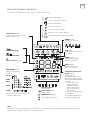
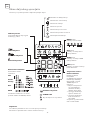
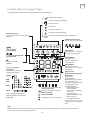
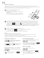
Remote Screen Indicators
Information are displayed when the remote controller is power up.
Breeze Away display
Active clean feature display
Fresh feature display
Sleep mode display
Follow me feature display
Wireless control feature display
Low battery detection display (If flashes)
MODE display
Displays the current
including:
ECO display
Displays when ECO feature
is activated
GEAR display
Displays when GEAR
feature is activated
LOCK display
Displays when LOCK
feature is activated.
Temperature/Timer/Fan
speed display
Displays the set
temperature by default, or
fan speed or timer setting
when using TIMER ON/OFF
functions.
• Temperature range:
16-30ºC/60-86ºF/
(20-28ºC/68-82ºF)
(Model dependent)
• Timer setting range:
0-24 hours
• Fan speed setting range:
AU -100%
This display is blank when
operating in FAN mode.
FAN SPEED display
Displays selected fan
speed:
TIMER ON display
TIMER OFF display
Silence feature display
Transmission Indicator
Lights up when remote sends
signal to indoor unit
This fan speed can not be adjusted
in AUTO or DRY mode.
Note:
All indicators shown in the figure are for the purpose of clear presentation. But during the actaul operation, only the
relative function signs are shown on the display window.
Silence
LOW
MED
HIGH
AUTO
Horizontal louver
swing display
Vertical louver auto
swing display
TURBO mode display
Not available for this unit

8
ENG
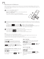
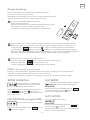
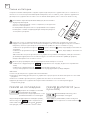
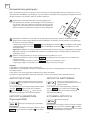
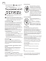
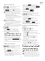
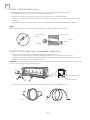
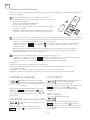
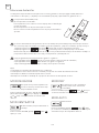
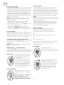
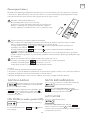
Use 2 pieces LRO3 AAA (1.5V) batteries.
Do not use rechargeable batteries.
Replace the old batteries with new ones of the same type when the
display is no longer legible.
Do not dispose batteries as unsorted municipal waste.
Collection of such waste separately for special treatment is necessary.
Each time when insert the batteries in the remote controller for the first time, you can set the Cooling only or
Heating pump control type. As soon as you insert the batteries, turn off the remote controller, and operate as
below.
1. Long press the
button, until the ( ) icon flash, to set the Cooling only type.
2. Long press the
button, until the ( ) icon flash, to set the Heating pump type.
Note: If you set the remote control in cooling mode, it will not be possible to activate the heating function in
units with a heating pump. If you need to reset, take out the batteries and install again.
You can program the temperature display between �C and �F.
1. Press and hold the
button over 5 seconds to get into the change mode;
2. Press and hold the
button, until it switch to �C and �F;
3. Then release the pressing and wait for 5 seconds, the function will be selected.
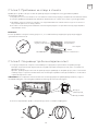
Replacement of Batteries
Remove the battery cover plate from the rear of the remote control, by pressing and sliding it in direction as the
arrow. Install the batteries by putting ( -) at the side with spring on the remote controller. Reinstall the battery cover
by sliding it into place.
Note:
1. Direct the remote control toward the Air conditioner.
2. Check that there are no objects between the remote control and the Signal receptor in the indoor unit.
3. Never leave the remote control exposed to the rays of the sun.
4. Keep the remote control at a distance of at least 1m from the television or other electrical appliances.
The cooling function allows the air
conditioner to cool the room and
reduce Air humidity at the same time.
Fan mode, air ventilation only.
To activate the cooling function (COOL), press the
button until the symbol appears on the
display. With the button
or set a temperature lower
than that of the room.
To set the FAN mode, press
until appears
on the display.
Cooling mode
FAN MODE (Not FAN button)
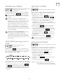
This function reduces the humidity
of the air to make the room more
comfortable.
To set the DRY mode, Press
until appears
in the display. An automatic function of pre-setting is
activated.
DRY MODE
Automatic mode.
To set the AUTO mode, press
until
appears on the display. In AUTO mode the run mode
will be set automatically according to the room
temperature.
AUTO MODE

9
ENG
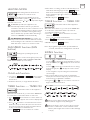
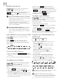
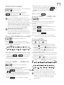
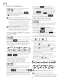
The heating function allows the air
conditioner to heat the room.
Change the operating fan speed.
To automatic switch on the appliance.
To automatic switch off the appliance.
To activate the heating function (HEAT), press the
button until the symbol appears on the
display. With the button
or set a temperature higher
than that of the room.
Press
button to set the running fan speed, it can
be set to AUTO/ MUTE/ LOW/ LOW-MID / MID/ MID-
HIGH/ HIGH/ TURBO speed circularly.
When the unit is switch-off, you can set the TIMER ON.
To set the time of automatic switch-on as below:
1. Press
button first time to set the switch-on,
and will appear on the remote display and
flashes.
2. Press
or to button to set desired Timer-on time.
Each time you press the button, the time increases/
decreases by half an hour between 0 and 10 hours
and by one between 10 and 24 hours.
3. Press
button second time to confirm.
When the unit is switch-on, you can set the TIMER OFF.
To set the time of automatic switch-off, as below:
1. Confirm the appliance is ON.
2. Press the
button at first time to set the
switch-off.
Press
or to set the needed timer.
3. Press
button at the second time to confirm.
CANCEL it by press
button.
Note: All programming should be operated within 5
seconds, otherwise the setting will be cancelled.
1. Press the button SWING to activate the louver,
1.1 Press
to activate the horizontal flaps to swing
from up to down, the
will appear on the remote
display.
1.2 Press
to active the vertical deflectors to swing
from left to right, the
will appear on the remote
display.
1.3 Do it again to stop the swing movement at the
current angle.
2. If the vertical deflectors are positioned manually
which placed under the flaps, they allow to move the
air flow direct to rightward or leftward.
3. Long press
or over 3 seconds to select more
angles of the airflow direction.
1. Long press
and button together
to active this function, and do it again to deactivate
this function.
2. Under this function, no single button will active.
HEATING MODE
FAN SPEED function (FAN
button)
TIMER function ---- TIMER ON
TIMER function ---- TIMER OFF
SWING function
Child-Lock function
In HEATING operation, the appliance can
automatically activate a defrost cycle, which is
essential to clean the frost on the condenser so as to
recover its heat exchange function. This procedure
usually lasts for 2-10 minutes. During defrosting,
indoor unit fan stop operation. After defrosting, it
resumes to HEATING mode automatically.
(For North American market) If necessary, you
can press ECO button 10 times within 8 seconds
under heating mode to start the forced defrosting.
It will defrost the outdoor ice much more fast.
4. After Timer-on setting, set the needed mode (Cool/
Heat/ Auto/ Fan/ Dry), by press the
button.
And set the needed fan speed, by press
button. And press
or to set the needed operation
temperature.
CANCEL it by press
button.
Never position Flaps manually, the delicate
mechanism might seriously damaged!
Never put fingers, sticks or other objects into the
air inlet or outlet vents. Such accidental contact
with live parts might cause unforeseeable damage
or injury.

10
ENG
Follow me function ( ):
The FOLLOW ME function enables the remote control
to measure the temperature at its current location and
send this signal to the air conditioner every 3 minutes
interval.
When using AUTO, COOL or HEAT modes, measuring
ambient temperature from the remote control(instead
of from the indoor unit itself) will enable the air
conditioner to optimize the temperature around you
and ensure maximum comfort.
NOTE: Press and hold Turbo button for seven seconds
to start/stop memory feature of Follow Me function. If
the memory feature is activated, “On” displays for 3
seconds on the screen.
• If the memory feature is activated, “On” displays for
3 seconds on the screen
• If the memory feature is stopped, “OFF” displays for
3 seconds on the screen.
• While the memory feature is activated, press the ON/
OFF button, shift the mode or power failure will not
cancel the Follow me function.
AP function (
) :
Choose AP mode to do wireless network configuration.
For some units, it doesn’t work by pressing the SET
button. To enter the AP mode, continuously press the
LED button seven times in 10 seconds.
Breeze Away function (
) (some units) :
This feature avoids direct air flow blowing on the body
and makes you feel indulging in silky coolness.
NOTE: This feature is available under cool, Fan and Dry
mode only.
FRESH function (
) (some units) :
When the FRESH function is initiated, the Ionizer/Plasma
Dust Collector(depending on models) is energized and
will help to remove pollen and impurities from the air.
Keep pressing Fan button for more
than 2 seconds to activate/disable
Silence Function (some units).
Due to low frequency operation
of compressor, it may result in
insufficient cooling and heating
capacity. Press ON/OFF, Mode,
Sleep, Turbo or Clean button while
operating will cancel silence function
Press LED button
Press this button to turn on and turn
off the display on the indoor unit.
Press this button more than 5
seconds(some units)
Keep pressing this button more than
5 seconds, the indoor unit will display
the actual room temperature.
Press more than 5 seconds again
will revert back to display the setting
temperature.
Press X-ECO button to enter the
energy efficient mode in a sequence
of following:
ECO -> GEAR(75%) -> GEAR(50%) ->
Previous setting mode -> ECO......
Note:This function is only available
under COOL mode.
Silence function
LED DISPLAY
ECO operation:
Under cooling mode, press this button, the remote
controller will adjust the temperature automatically
to 24ºC/75ºF, fan speed of Auto to save energy (only
when the set temperature is less than 24ºC/75ºF). If
the set temperature is above 24ºC/75ºF, press the
ECO button, the fan speed will change to Auto, the set
temperature will remain unchanged.
NOTE:
Pressing the ECO button, or modifying the mode or
adjusting the set temperature to less than 24ºC/75ºF
will stop ECO operation.
Under ECO operation, the set tmeperature should be
24ºC/75ºF or above, it may result in insufficient cooling.
If you feel uncomfortable, just press the ECO button
again to stop it.
GEAR operation:
Press the ECO/GEAR button to enter the GEAR
operation as following:
75%(up to 75% electrial energy consumption)
50%(up to 50% electrial energy consumption)
Previous setting mode.
Under GEAR operation, the display on the remote
controller will alternage between electical energy
consumption and set temperature.
ECO/GEAR function

11
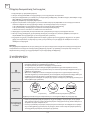
ENG
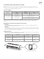
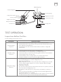
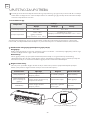
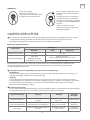
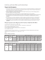
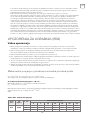
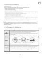
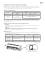
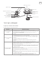
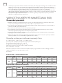
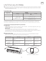
Attempt to use the air conditioner under the temperature beyond the specified range may cause the air
conditioner protection device to start and the air conditioner may fail to operate. Therefore, try to use the air
conditioner in the following temperature conditions.
Characteristics of heating operation (applicable to Heating pump)
Preheating:
When the heating function is enabled, the indoor unit will take 2~5 minutes for preheating, after that the air
conditioner will start heating and blows warm air.
Defrosting:
During heating, when the outdoor unit frosted, the air conditioner will enable the automatic defrosting function
to improve the heating effect. During defrosting, the indoor and outdoor fans stop running. The air conditioner
will resume heating automatically after defrosting finish.
With the power supply connected, restart the air conditioner after shutdown, or switch it to other mode during
operation, and the air conditioner protection device will start. The compressor will resume operation after 3
minutes.
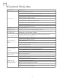
Temperature
Mode
Heating Cooling Dry
Room temperature 0°C~30°C 17°C~32°C
Outdoor temperature
-20°C~30°C
(Low temperature heating:
-25°C~30°C)
T1 climate: 15°C~53°C
(Low temperature cooling: -15°C~53°C)
T3 climate: 15°C~55°C
Inverter air conditioner:
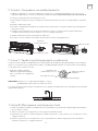
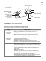
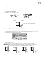
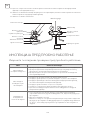
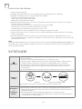
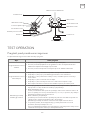
OPERATION INSTRUCTIONS
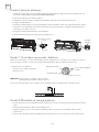
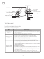
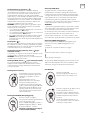
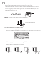
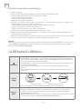
Emergency button:
Open the panel and find the emergency button on the electronic control box when the remote controller fails .
(Always press the emergency button with insulation material.)
Current status Operation Respond Enter mode
Standby Press the emergency button once It beeps briefly once. Cooling mode
Standby (Only for
heating pump)
Press the emergency button twice
in 3 seconds
It beeps briefly twice. Heating mode
Running Press the emergency button once
It keeps beeping for a
while
Off mode
control-box cover
(open the panel of indoor unit)
ON/OFF

12
ENG
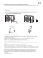
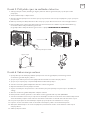
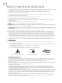
INSTRUCTION FOR SERVICING (R32)
1. Check the information in this manual to find out the dimensions of space needed for proper installation of the
device, including the minimum distances allowed compared to adjacent structures.
2. Appliance shall be installed, operated and stored in a room with a floor area larger than 4m
2
.
3. The installation of pipe-work shall be kept to a minimum.
4. The pipe-work shall be protected from physical damage, and shall not be installed in an unventilated space if
the space is smaller than 4m
2
.
5. The compliance with national gas regulations shall be observed.
6. The mechanical connections shall be accessible for maintenance purposes.
7. Follow the instructions given in this manual for handling, installing, cleaning, maintaining and disposing of the
refrigerant.
8. Make sure ventilation openings clear of obstruction.
9. Notice:The servicing shall be performed only as recommended by the manufacturer.
10. Warning: The appliance shall be stored in a well-ventilated area where the room size corresponds to the room
area as specified for operation.
11. Warning:The appliance shall be stored in a room without continuously operating open flames (for example
an operating gas appliance) and ignition sources (for example an operating electric heater).
12. The appliance shall be stored so as to prevent mechanical damage from occurring.
13. It is appropriate that anyone who is called upon to work on a refrigerant circuit should hold a valid and up-to-
date certificate from an assessment authority accredited by the industry and recognizing their competence
to handle refrigerants, in accordance with the assessment specification recognized in the industrial sector
concerned. Service operations should only be carried out in accordance with the recommendations of the
equipment manufacturer. Maintenance and repair operations that require the assistance of other qualified
persons must be conducted under the supervision of the person competent for the use of flammable
refrigerants.
14. Every working procedure that affects safety means shall only be carried out by competent persons.
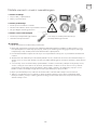
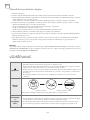
15. Warning:
• Do not use means to accelerate the defrosting process or to clean, other than those recommended by the
manufacturer.
• The appliance shall be stored in a room without continuously operating ignition sources (for example: open
flames, an operating gas appliance or an operating electric heater.
• Do not pierce or burn.
• Be aware that refrigerants may not contain an odour.
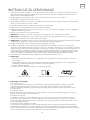
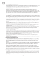
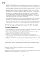
Caution: Risk of fire Operating instructions Read technical manual
16. Information on servicing:
1. Checks to the area
Prior to beginning work on systems containing flammable refrigerants, safety checks are necessary to ensure
that the risk of ignition is minimized. For repair to the refrigerating system, the following precautions shall be
complied with prior to conducting work on the system.
2. Work procedure
Work shall be undertaken under a controlled procedure so as to minimize the risk of a flammable gas or
vapour being present while the work is being performed.
3. General work area
All maintenance staff and others working in the local area shall be instructed on the nature of work being
carried out. Work in confined spaces shall be avoided. The area around the workspace shall be sectioned off.
Ensure that the conditions within the area have been made safe by control of flammable material.
4. Checking for presence of refrigerant
The area shall be checked with an appropriate refrigerant detector prior to and during work, to ensure the
technician is aware of potentially flammable atmospheres. Ensure that the leak detection equipment being
used is suitable for use with flammable refrigerants, i.e. non-sparking, adequately sealed or intrinsically safe
5. Presence of fire extinguisher
If any hot work is to be conducted on the refrigeration equipment or any associated parts, appropriate fire

13
ENG
extinguishing equipment shall be available to hand. Have a dry powder or CO2 fire extinguisher adjacent to
the charging area.
6. No ignition sources
No person carrying out work in relation to a refrigeration system which involves exposing any pipe work shall
use any sources of ignition in such a manner that it may lead to the risk of fire or explosion. All possible ignition
sources, including cigarette smoking, should be kept sufficiently far away from the site of installation, repairing,
removing and disposal, during which refrigerant can possibly be released to the surrounding space. Prior to
work taking place, the area around the equipment is to be surveyed to make sure that there are no flammable
hazards or ignition risks. “No Smoking” signs shall be displayed.
7. Ventilated area
Ensure that the area is in the open or that it is adequately ventilated before breaking into the system or
conducting any hot work. A degree of ventilation shall continue during the period that the work is carried
out. The ventilation should safely disperse any released refrigerant and preferably expel it externally into the
atmosphere.
8. Checks to the refrigeration equipment
Where electrical components are being changed, they shall be fit for the purpose and to the correct
specification. At all times the manufacturer’s maintenance and service guidelines shall be followed. If in doubt
consult the manufacturer’s technical department for assistance.
The following checks shall be applied to installations using flammable refrigerants:
- The charge size is in accordance with the room size within which the refrigerant containing parts are installed;
- The ventilation machinery and outlets are operating adequately and are not obstructed;
- If an indirect refrigerating circuit is being used, the secondary circuit shall be checked for the presence of
refrigerant;
- Marking to the equipment continues to be visible and legible. Markings and signs that are illegible shall be
corrected;
- Refrigeration pipe or components are installed in a position where they are unlikely to be exposed to any
substance which may corrode refrigerant containing components, unless the components are constructed of
materials which are inherently resistant to being corroded or are suitably protected against being so corroded.
9. Checks to electrical devices
Repair and maintenance to electrical components shall include initial safety checks and component inspection
procedures. If a fault exists that could compromise safety, then no electrical supply shall be connected to
the circuit until it is satisfactorily dealt with. If the fault cannot be corrected immediately but it is necessary to
continue operation, an adequate temporary solution shall be used. This shall be reported to the owner of the
equipment so all parties are advised.
Initial safety checks shall include:
-That capacitors are discharged: this shall be done in a safe manner to avoid possibility of sparking;
-That there no live electrical components and wiring are exposed while charging, recovering or purging the
system;
-That there is continuity of earth bonding.
17. Repairs to sealed components
1. During repairs to sealed components, all electrical supplies shall be disconnected from the equipment
being worked upon prior to any removal of sealed covers, etc. If it is absolutely necessary to have an electrical
supply to equipment during servicing, then a permanently operating form of leak detection shall be located at
the most critical point to warn of a potentially hazardous situation.
2. Particular attention shall be paid to the following to ensure that by working on electrical components, the
casing is not altered in such a way that the level of protection is affected. This shall include damage to cables,
excessive number of connections, terminals not made to original specification, damage to seals, incorrect
fitting of glands, etc.
Ensure that apparatus is mounted securely.
Ensure that seals or sealing materials have not degraded such that they no longer serve the purpose of
preventing the ingress of flammable atmospheres. Replacement parts shall be in accordance with the
manufacturer’s specifications.
NOTE: The use of silicon sealant may inhibit the effectiveness of some types of leak detection equipment.
Intrinsically safe components do not have to be isolated prior to working on them.
18. Repair to intrinsically safe components
Do not apply any permanent inductive or capacitance loads to the circuit without ensuring that this will not
exceed the permissible voltage and current permitted for the equipment in use.
Intrinsically safe components are the only types that can be worked on while live in the presence of a
flammable atmosphere. The test apparatus shall be at the correct rating.

14
ENG
Replace components only with parts specified by the manufacturer. Other parts may result in the ignition of
refrigerant in the atmosphere from a leak.
19. Cabling
Check that cabling will not be subject to wear, corrosion, excessive pressure, vibration, sharp edges or any
other adverse environmental effects. The check shall also take into account the effects of aging or continual
vibration from sources such as compressors or fans.
20. Detection of flammable refrigerants
Under no circumstances shall potential sources of ignition be used in the searching for or detection of
refrigerant leaks. Ahalide torch (or any other detector using a naked flame) shall not be used.
21. Leak detection methods
The following leak detection methods are deemed acceptable for systems containing flammable refrigerants.
Electronic leak detectors shall be used to detect flammable refrigerants, but the sensitivity may not be
adequate, or may need re-calibration. (Detection equipment shall be calibrated in a refrigerant-free area.)
Ensure that the detector is not a potential source of ignition and is suitable for the refrigerant used. Leak
detection equipment shall be set at a percentage of the LFL of the refrigerant and shall be calibrated to the
refrigerant employed and the appropriate percentage of gas (25 % maximum) is confirmed.
Leak detection fluids are suitable for use with most refrigerants but the use of detergents containing chlorine
shall be avoided as the chlorine may react with the refrigerant and corrode the copper pipe-work.
If a leak is suspected, all naked flames shall be removed/ extinguished.
If a leakage of refrigerant is found which requires brazing, all of the refrigerant shall be recovered from the
system, or isolated (by means of shut off valves) in a part of the system remote from the leak. Oxygen free
nitrogen (OFN) shall then be purged through the system both before and during the brazing process.
22. Removal and evacuation
When breaking into the refrigerant circuit to make repairs or for any other purpose conventional procedures
shall be used. However, it is important that best practice is followed since flammability is a consideration. The
following procedure shall be adhered to:
- Remove refrigerant;
- Purge the circuit with inert gas;
- Evacuate;
- Purge again with inert gas;
-Open the circuit by cutting or brazing.
The refrigerant charge shall be recovered into the correct recovery cylinders. The system shall be flushed
with OFN to render the unit safe. This process may need to be repeated several times. Compressed air or
oxygen shall not be used for this task.
Flushing shall be achieved by breaking the vacuum in the system with OFN and continuing to fill until the
working pressure is achieved, then venting to atmosphere, and finally pulling down to a vacuum. This process
shall be repeated until no refrigerant is within the system. When the final OFN charge is used, the system shall
be vented down to atmospheric pressure to enable work to take place. This operation is absolutely vital if
brazing operations on the pipe-work are to take place.
Ensure that the outlet for the vacuum pump is not close to any ignition sources and there is ventilation
available.
23. Decommissioning
Before carrying out this procedure, it is essential that the technician is completely familiar with the equipment
and all its detail. It is recommended good practice that all refrigerants are recovered safely. Prior to the task
being carried out, an oil and refrigerant sample shall be taken in case analysis is required prior to re-use of
reclaimed refrigerant. It is essential that electrical power is available before the task is commenced.
a. Become familiar with the equipment and its operation.
b. Isolate system electrically.
c. Before attempting the procedure, ensure that:
- mechanical handling equipment is available, if required, for handling refrigerant cylinders;
- all personal protective equipment is available and being used correctly;
- the recovery process is supervised at all times by a competent person;
- recovery equipment and cylinders conform to the appropriate standards.
d. Pump down refrigerant system, if possible.
e. If a vacuum is not possible, make a manifold so that refrigerant can be removed from various parts of the
system.
f. Make sure that cylinder is situated on the scales before recovery takes place.
g. Start the recovery machine and operate in accordance with manufacturer’s instructions.
h. Do not overfill cylinders. (No more than 80 % volume liquid charge).
i. Do not exceed the maximum working pressure of the cylinder, even temporarily.

15
ENG
j. When the cylinders have been filled correctly and the process completed, make sure that the cylinders and
the equipment are removed from site promptly and all isolation valves onthe equipment are closed off.
k. Recovered refrigerant shall not be charged into another refrigeration system unless it has been cleaned and
checked.
24. Labelling
Equipment shall be labelled stating that it has been de-commissioned and emptied of refrigerant. The label
shall be dated and signed. Ensure that there are labels on the equipment stating the equipment contains
flammable refrigerant.
25. Recovery
When removing refrigerant from a system, either for servicing or decommissioning, it is recommended good
practice that all refrigerants are removed safely.
When transferring refrigerant into cylinders, ensure that only appropriate refrigerant recovery cylinders are
employed. Ensure that the correct number of cylinders for holding the total system charge are available. All
cylinders to be used are designated for the recovered refrigerant and labelled for that refrigerant (i.e. special
cylinders for the recovery of refrigerant). Cylinders shall be complete with pressure-relief valve and associated
shut-off valves in good working order. Empty recovery cylinders are evacuated and, if possible, cooled before
recovery occurs.
The recovery equipment shall be in good working order with a set of instructions concerning the equipment
that is at hand and shall be suitable for the recovery of all appropriate refrigerants including, when applicable,
flammable refrigerants. In addition, a set of calibrated weighing scales shall be available and in good working
order. Hoses shall be complete with leak-free disconnect couplings and in good condition. Before using the
recovery machine, check that it is in satisfactory working order, has been properly maintained and that any
associated electrical components are sealed to prevent ignition in the event of a refrigerant release. Consult
manufacturer if in doubt.
The recovered refrigerant shall be returned to the refrigerant supplier in the correct recover cylinder, and the
relevant waste transfer note arranged. Do not mix refrigerants in recovery units and especially not in cylinders.
If compressors or compressor oils are to be removed, ensure that they have been evacuated to an acceptable
level to make certain that flammable refrigerant does not remain within the lubricant. The evacuation process
shall be carried out prior to returning the compressor to the suppliers. Only electric heating to the compressor
body shall be employed to accelerate this process. When oil is drained from a system, it shall be carried out
safely.

ENG
INSTALLATION PRECAUTIONS (R32)
Important considerations
1. The air conditioner you buy must be installed by professional personnel and the Installation manual is used
only for the professional installation personnel! The installation specifications should be subject to our after-
sale service regulations.
2. When filling the combustible refrigerant, any of your rude operations may cause serious injury or injuries to
human body or bodies and object or objects.
3. A leak test must be done after the installation is completed.
4. It is a must to do the safety inspection before maintaining or repairing an air conditioner using combustible
refrigerant in order to ensure that the fire risk is reduced to minimum.
5. It is necessary to operate the machine under a controlled procedure in order to ensure that any risk arising
from the combustible gas or vapor during the operation is reduced to minimum.
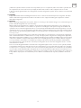
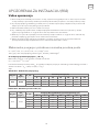
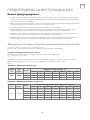
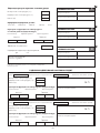
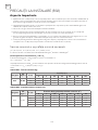
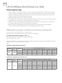
6. Requirements for the total weight of filled refrigerant and the area of a room to be equipped with an air
conditioner (are shown as in the following Tables GG.1 and GG.2)
The maximum charge and the required minimum floor area
m
1
= (4 m
3
) x LFL , m
2
= (26 m
3
) x LFL, m
3
= (130 m
3
) x LFL
Where LFL is the lower flammable limit in kg/m
3
, R32 LFL is 0.038 kg/m
3
.
For the appliances with a charge amount m
1
< M = m
2
:
The maximum charge in a room shall be in accordance with the following:
m
max
= 2.5 x (LFL)
(5/4)
x h
0
x (A)
1/2
The required minimum floor area A
min
to install an appliance with refrigerant charge M (kg) shall be in accordance
with following: A
min
= (M/ (2.5 x (LFL)
(5/4)
x h
0
))
2
Where:
Category
LFL
(kg/m
3
)
h
0
(m)
Floor area (m
2
)
4 7 10 15 20 30 50
R32 0.306
1 1.14 1.51 1.8 2.2 2.54 3.12 4.02
1.8 2.05 2.71 3.24 3.97 4.58 5.61 7.254
2.2 2.5 3.31 3.96 4.85 5.6 6.86 8.85
Table GG.1 - Maximum charge (kg)
Category
LFL
(kg/m
3
)
h
0
(m)
Charge amount (M) (kg) Minimum room area (m
2
)
4 7 10 15 20 30 50
R32 0.306
1.224kg 1.836kg 2.448kg 3.672kg 4.896kg 6.12kg 7.956kg
0.6 29 51 116 206 321 543
1 10 19 42 74 116 196
1.8 3 6 13 23 36 60
2.2 2 4 9 15 24 40
Table GG.2 - Minimum room area (m
2
)

17
ENG
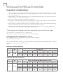
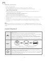
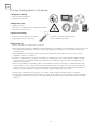
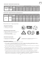
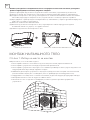
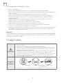
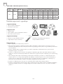
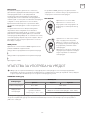
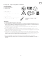
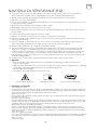
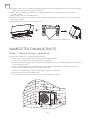
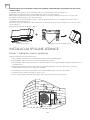
Installation Safety Principles
1. Site Safety
2. Operation Safety
3. Installation Safety
• Open Flames Prohibited
• Ventilation Necessary
• Mind Static Electricity
• Must wear protective clothing and anti-static gloves
• Don`t use mobile phone
• Refrigerant Leak Detector
• Appropriate Installation Location
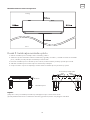
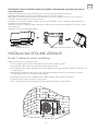
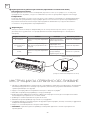
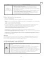
Please note that:
1. The installation site should be well-ventilated.
2. The sites for installing and maintaining an air conditioner using Refrigerant R32 should be free from open fire
or welding, smoking, drying oven or any other heat source higher than 548 which easily produces open fire.
3. When installing an air conditioner, it is necessary to take appropriate anti-static measures such as wear anti-
static clothing and/or gloves.
4. It is necessary to choose the site convenient for installation or maintenance wherein the air inlets and outlets
of the indoor and outdoor units should be not surrounded by obstacles or close to any heat source or
combustible and/or explosive environment.
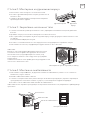
5. If the indoor unit suffers refrigerant leak during the installation, it is necessary to immediately turn off the valve
of the outdoor unit and all the personnel should go out till the refrigerant leaks completely for 15 minutes. If
the product is damaged, it is a must to carry such damaged product back to the maintenance station and it is
prohibited to weld the refrigerant pipe or conduct other operations on the user’s site.
6. It is necessary to choose the place where the inlet and outlet air of the indoor unit is even.
7. It is necessary to avoid the places where there are other electrical products, power switch plugs and sockets,
kitchen cabinet, bed, sofa and other valuables right under the lines on two sides of the indoor unit.
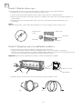
The left picture is the schematic diagram
of a refrigerant leak detector.

18
ENG
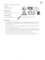
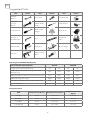
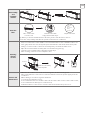
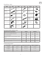
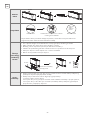
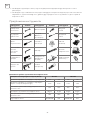
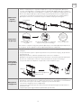
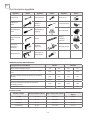
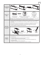
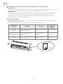
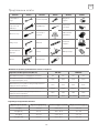
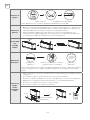
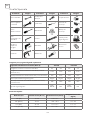
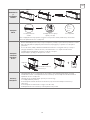
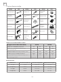
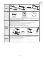
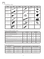
Suggested Tools
Tool Picture Tool Picture Tool Picture
Standard
Wrench
Pipe Cutter Vacuum Pump
Adjustable/
Crescent
Wrench
Screw drivers
(Phillips & Flat
blade)
Safety Glasses
Torque Wrench
Manifold and
Gauges
Work Gloves
Hex Keys or
Allen Wrenches
Level
Refrigerant
Scale
Drill & Drill Bits Flaring tool Micron Gauge
Hole Saw
Clamp on Amp
Meter
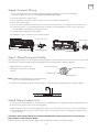
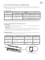
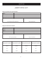
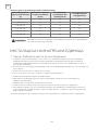
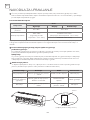
Inverter Models Capacity (Btu/h) 9K-12K 18K-36K
Lenght of pipe with standard charge 5m 5m 5m 5m
Lenght of pipe with standard charge (Like: North
American, etc.)
7.5m 7.5m 7.5m 7.5m
Maximum distance between indoor and outdoor unit 15m 25m 25m 25m
Additional refrigerant charge 20g/m 15g/m 30g/m 25g/m
Max. diff. in level between indoor and outdoor unit 10m 10m 10m 10m
Type of refrigerant R22/R410A R32 R22/R410A R32
Pipe Length and Additional Refrigerant
PIPE Newton meter [N x m] Pound-force foot (1bf-ft)
Kilogram-force meter
(kgf-m)
1/4" (ɸ6) 18 - 20 24.4 - 27.1 2.4 - 2.7
3/8” (ɸ9.52) 30 - 35 40.6 - 47.4 4.1 - 4.8
1/2” (ɸ12) 45 - 50 61.0 - 67.7 6.2 - 6.9
5/8” (ɸ15.88) 60 - 65 81.3 - 88.1 8.2 - 8.9
Torque Parameters

19
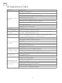
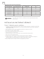
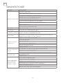
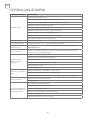
ENG
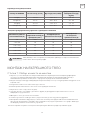
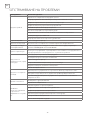
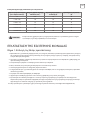
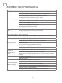
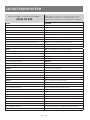
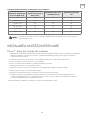
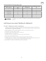
This table is only for reference, the installation shall meet the requirements of local laws
and regulations.
NOTE
Maximum Operating
Current of Air
Conditioner (A)
Minimum Wire Cross-
sectional Area (mm
2
)
Specification of Socket
or Switch (A)
Fuse Specification (A)
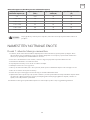
≤ 8 0.75 10 20
> 8 and ≤10 1.0 10 20
> 10 and ≤15 1.5 16 32
> 15 and ≤24 2.5 25 32
> 24 and ≤28 4.0 32 64
> 28 and ≤32 6.0 40 64
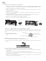
Dedicated Distribution Device and Wire for Air Conditioner
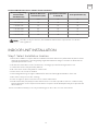
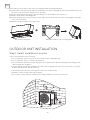
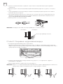
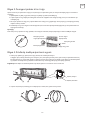
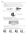
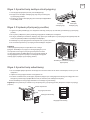
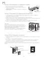
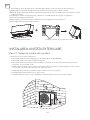
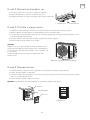
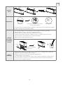
Step1: Select Installation location
1. Ensure the installation complies with the installation minimum dimensions (defined below) and meets the
minimum and maximum connecting piping length and maximum change in elevation as defined in the
System Requirements section.
2. Air inlet and outlet will be clear of obstructions, ensuring proper airflow throughout the room.
3. Condensate can be easily and safely drained.
4. All connections can be easily made to outdoor unit.
5. Indoor unit is out of reach of children.
6. A mounting wall strong enough to withstand four times the full weight and vibration of the unit.
7. Filter can be easily accessed for cleaning.
8. Leave enough free space to allow access for routine maintenance.
9. Install at least 10 ft. (3 m) away from the antenna of TV set or radio. Operation of the air conditioner may
interfere with radio or TV reception in areas where reception is weak. An amplifier may be required for the
affected device.
10. Do not install in a laundry room or by a swimming pool due to the corrosive environment.
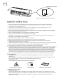
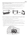
INDOOR UNIT INSTALLATION

20
ENG
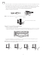
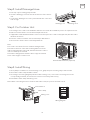
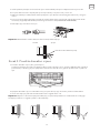
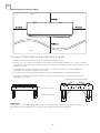
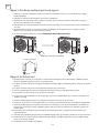
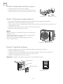
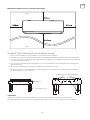
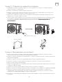
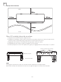
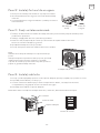
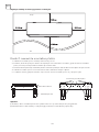
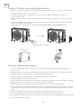
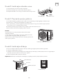
NOTE:
(I) Make sure the mounting plate is firm enough and flat against the wall after installation.
(II) This figure shown may be different from the actual object, please take the latter as the standard.
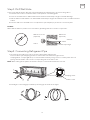
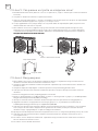
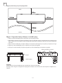
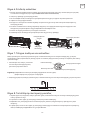
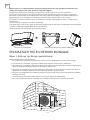
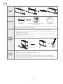
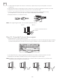
Step2: Install Mounting Plate
Minimum Indoor Clearances
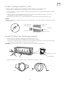
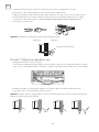
1. Take the mounting plate from the back of indoor unit.
2. Ensure to meet the minimum installation dimension requirements as step 1, according to the size of mounting
plate, determine the position and stick the mounting plate close to the wall.
3. Adjust the mounting plate to a horizontal state with a spirit level, then mark out the screw hole positions on the
wall.
4. Put down the mounting plate and drill holes in the marked positions with drill.
5. Insert expansion rubber plugs into the holes, then hang the mounting plate and fix it with screws.
Ceiling
Floor
Reference screw positions
Spirit level
Mounting plate
Pagina se încarcă...
Pagina se încarcă...
Pagina se încarcă...
Pagina se încarcă...
Pagina se încarcă...
Pagina se încarcă...
Pagina se încarcă...
Pagina se încarcă...
Pagina se încarcă...
Pagina se încarcă...
Pagina se încarcă...
Pagina se încarcă...
Pagina se încarcă...
Pagina se încarcă...
Pagina se încarcă...
Pagina se încarcă...
Pagina se încarcă...
Pagina se încarcă...
Pagina se încarcă...
Pagina se încarcă...
Pagina se încarcă...
Pagina se încarcă...
Pagina se încarcă...
Pagina se încarcă...
Pagina se încarcă...
Pagina se încarcă...
Pagina se încarcă...
Pagina se încarcă...
Pagina se încarcă...
Pagina se încarcă...
Pagina se încarcă...
Pagina se încarcă...
Pagina se încarcă...
Pagina se încarcă...
Pagina se încarcă...
Pagina se încarcă...
Pagina se încarcă...
Pagina se încarcă...
Pagina se încarcă...
Pagina se încarcă...
Pagina se încarcă...
Pagina se încarcă...
Pagina se încarcă...
Pagina se încarcă...
Pagina se încarcă...
Pagina se încarcă...
Pagina se încarcă...
Pagina se încarcă...
Pagina se încarcă...
Pagina se încarcă...
Pagina se încarcă...
Pagina se încarcă...
Pagina se încarcă...
Pagina se încarcă...
Pagina se încarcă...
Pagina se încarcă...
Pagina se încarcă...
Pagina se încarcă...
Pagina se încarcă...
Pagina se încarcă...
Pagina se încarcă...
Pagina se încarcă...
Pagina se încarcă...
Pagina se încarcă...
Pagina se încarcă...
Pagina se încarcă...
Pagina se încarcă...
Pagina se încarcă...
Pagina se încarcă...
Pagina se încarcă...
Pagina se încarcă...
Pagina se încarcă...
Pagina se încarcă...
Pagina se încarcă...
Pagina se încarcă...
Pagina se încarcă...
Pagina se încarcă...
Pagina se încarcă...
Pagina se încarcă...
Pagina se încarcă...
Pagina se încarcă...
Pagina se încarcă...
Pagina se încarcă...
Pagina se încarcă...
Pagina se încarcă...
Pagina se încarcă...
Pagina se încarcă...
Pagina se încarcă...
Pagina se încarcă...
Pagina se încarcă...
Pagina se încarcă...
Pagina se încarcă...
Pagina se încarcă...
Pagina se încarcă...
Pagina se încarcă...
Pagina se încarcă...
Pagina se încarcă...
Pagina se încarcă...
Pagina se încarcă...
Pagina se încarcă...
Pagina se încarcă...
Pagina se încarcă...
Pagina se încarcă...
Pagina se încarcă...
Pagina se încarcă...
Pagina se încarcă...
Pagina se încarcă...
Pagina se încarcă...
Pagina se încarcă...
Pagina se încarcă...
Pagina se încarcă...
Pagina se încarcă...
Pagina se încarcă...
Pagina se încarcă...
Pagina se încarcă...
Pagina se încarcă...
Pagina se încarcă...
Pagina se încarcă...
Pagina se încarcă...
Pagina se încarcă...
Pagina se încarcă...
Pagina se încarcă...
Pagina se încarcă...
Pagina se încarcă...
Pagina se încarcă...
Pagina se încarcă...
Pagina se încarcă...
Pagina se încarcă...
Pagina se încarcă...
Pagina se încarcă...
Pagina se încarcă...
Pagina se încarcă...
Pagina se încarcă...
Pagina se încarcă...
Pagina se încarcă...
Pagina se încarcă...
Pagina se încarcă...
Pagina se încarcă...
Pagina se încarcă...
Pagina se încarcă...
Pagina se încarcă...
Pagina se încarcă...
Pagina se încarcă...
Pagina se încarcă...
Pagina se încarcă...
Pagina se încarcă...
Pagina se încarcă...
Pagina se încarcă...
Pagina se încarcă...
Pagina se încarcă...
Pagina se încarcă...
Pagina se încarcă...
Pagina se încarcă...
Pagina se încarcă...
Pagina se încarcă...
Pagina se încarcă...
Pagina se încarcă...
Pagina se încarcă...
Pagina se încarcă...
Pagina se încarcă...
Pagina se încarcă...
Pagina se încarcă...
Pagina se încarcă...
Pagina se încarcă...
Pagina se încarcă...
Pagina se încarcă...
Pagina se încarcă...
Pagina se încarcă...
Pagina se încarcă...
Pagina se încarcă...
Pagina se încarcă...
Pagina se încarcă...
Pagina se încarcă...
Pagina se încarcă...
Pagina se încarcă...
Pagina se încarcă...
Pagina se încarcă...
Pagina se încarcă...
Pagina se încarcă...
Pagina se încarcă...
Pagina se încarcă...
Pagina se încarcă...
Pagina se încarcă...
Pagina se încarcă...
Pagina se încarcă...
Pagina se încarcă...
Pagina se încarcă...
Pagina se încarcă...
Pagina se încarcă...
Pagina se încarcă...
Pagina se încarcă...
Pagina se încarcă...
Pagina se încarcă...
Pagina se încarcă...
Pagina se încarcă...
Pagina se încarcă...
Pagina se încarcă...
Pagina se încarcă...
Pagina se încarcă...
Pagina se încarcă...
Pagina se încarcă...
Pagina se încarcă...
Pagina se încarcă...
Pagina se încarcă...
Pagina se încarcă...
Pagina se încarcă...
Pagina se încarcă...
Pagina se încarcă...
Pagina se încarcă...
Pagina se încarcă...
Pagina se încarcă...
Pagina se încarcă...
Pagina se încarcă...
Pagina se încarcă...
Pagina se încarcă...
Pagina se încarcă...
Pagina se încarcă...
Pagina se încarcă...
Pagina se încarcă...
Pagina se încarcă...
Pagina se încarcă...
Pagina se încarcă...
Pagina se încarcă...
Pagina se încarcă...
Pagina se încarcă...
Pagina se încarcă...
Pagina se încarcă...
Pagina se încarcă...
Pagina se încarcă...
Pagina se încarcă...
Pagina se încarcă...
Pagina se încarcă...
Pagina se încarcă...
Pagina se încarcă...
Pagina se încarcă...
Pagina se încarcă...
Pagina se încarcă...
Pagina se încarcă...
Pagina se încarcă...
Pagina se încarcă...
Pagina se încarcă...
Pagina se încarcă...
Pagina se încarcă...
Pagina se încarcă...
Pagina se încarcă...
Pagina se încarcă...
Pagina se încarcă...
Pagina se încarcă...
Pagina se încarcă...
Pagina se încarcă...
Pagina se încarcă...
Pagina se încarcă...
Pagina se încarcă...
Pagina se încarcă...
Pagina se încarcă...
Pagina se încarcă...
Pagina se încarcă...
Pagina se încarcă...
Pagina se încarcă...
Pagina se încarcă...
Pagina se încarcă...
Pagina se încarcă...
Pagina se încarcă...
Pagina se încarcă...
Pagina se încarcă...
Pagina se încarcă...
Pagina se încarcă...
Pagina se încarcă...
Pagina se încarcă...
Pagina se încarcă...
Pagina se încarcă...
Pagina se încarcă...
Pagina se încarcă...
Pagina se încarcă...
Pagina se încarcă...
Pagina se încarcă...
Pagina se încarcă...
Pagina se încarcă...
Pagina se încarcă...
Pagina se încarcă...
Pagina se încarcă...
Pagina se încarcă...
Pagina se încarcă...
Pagina se încarcă...
Pagina se încarcă...
Pagina se încarcă...
-
 1
1
-
 2
2
-
 3
3
-
 4
4
-
 5
5
-
 6
6
-
 7
7
-
 8
8
-
 9
9
-
 10
10
-
 11
11
-
 12
12
-
 13
13
-
 14
14
-
 15
15
-
 16
16
-
 17
17
-
 18
18
-
 19
19
-
 20
20
-
 21
21
-
 22
22
-
 23
23
-
 24
24
-
 25
25
-
 26
26
-
 27
27
-
 28
28
-
 29
29
-
 30
30
-
 31
31
-
 32
32
-
 33
33
-
 34
34
-
 35
35
-
 36
36
-
 37
37
-
 38
38
-
 39
39
-
 40
40
-
 41
41
-
 42
42
-
 43
43
-
 44
44
-
 45
45
-
 46
46
-
 47
47
-
 48
48
-
 49
49
-
 50
50
-
 51
51
-
 52
52
-
 53
53
-
 54
54
-
 55
55
-
 56
56
-
 57
57
-
 58
58
-
 59
59
-
 60
60
-
 61
61
-
 62
62
-
 63
63
-
 64
64
-
 65
65
-
 66
66
-
 67
67
-
 68
68
-
 69
69
-
 70
70
-
 71
71
-
 72
72
-
 73
73
-
 74
74
-
 75
75
-
 76
76
-
 77
77
-
 78
78
-
 79
79
-
 80
80
-
 81
81
-
 82
82
-
 83
83
-
 84
84
-
 85
85
-
 86
86
-
 87
87
-
 88
88
-
 89
89
-
 90
90
-
 91
91
-
 92
92
-
 93
93
-
 94
94
-
 95
95
-
 96
96
-
 97
97
-
 98
98
-
 99
99
-
 100
100
-
 101
101
-
 102
102
-
 103
103
-
 104
104
-
 105
105
-
 106
106
-
 107
107
-
 108
108
-
 109
109
-
 110
110
-
 111
111
-
 112
112
-
 113
113
-
 114
114
-
 115
115
-
 116
116
-
 117
117
-
 118
118
-
 119
119
-
 120
120
-
 121
121
-
 122
122
-
 123
123
-
 124
124
-
 125
125
-
 126
126
-
 127
127
-
 128
128
-
 129
129
-
 130
130
-
 131
131
-
 132
132
-
 133
133
-
 134
134
-
 135
135
-
 136
136
-
 137
137
-
 138
138
-
 139
139
-
 140
140
-
 141
141
-
 142
142
-
 143
143
-
 144
144
-
 145
145
-
 146
146
-
 147
147
-
 148
148
-
 149
149
-
 150
150
-
 151
151
-
 152
152
-
 153
153
-
 154
154
-
 155
155
-
 156
156
-
 157
157
-
 158
158
-
 159
159
-
 160
160
-
 161
161
-
 162
162
-
 163
163
-
 164
164
-
 165
165
-
 166
166
-
 167
167
-
 168
168
-
 169
169
-
 170
170
-
 171
171
-
 172
172
-
 173
173
-
 174
174
-
 175
175
-
 176
176
-
 177
177
-
 178
178
-
 179
179
-
 180
180
-
 181
181
-
 182
182
-
 183
183
-
 184
184
-
 185
185
-
 186
186
-
 187
187
-
 188
188
-
 189
189
-
 190
190
-
 191
191
-
 192
192
-
 193
193
-
 194
194
-
 195
195
-
 196
196
-
 197
197
-
 198
198
-
 199
199
-
 200
200
-
 201
201
-
 202
202
-
 203
203
-
 204
204
-
 205
205
-
 206
206
-
 207
207
-
 208
208
-
 209
209
-
 210
210
-
 211
211
-
 212
212
-
 213
213
-
 214
214
-
 215
215
-
 216
216
-
 217
217
-
 218
218
-
 219
219
-
 220
220
-
 221
221
-
 222
222
-
 223
223
-
 224
224
-
 225
225
-
 226
226
-
 227
227
-
 228
228
-
 229
229
-
 230
230
-
 231
231
-
 232
232
-
 233
233
-
 234
234
-
 235
235
-
 236
236
-
 237
237
-
 238
238
-
 239
239
-
 240
240
-
 241
241
-
 242
242
-
 243
243
-
 244
244
-
 245
245
-
 246
246
-
 247
247
-
 248
248
-
 249
249
-
 250
250
-
 251
251
-
 252
252
-
 253
253
-
 254
254
-
 255
255
-
 256
256
-
 257
257
-
 258
258
-
 259
259
-
 260
260
-
 261
261
-
 262
262
-
 263
263
-
 264
264
-
 265
265
-
 266
266
-
 267
267
-
 268
268
-
 269
269
-
 270
270
-
 271
271
-
 272
272
-
 273
273
-
 274
274
-
 275
275
-
 276
276
-
 277
277
-
 278
278
-
 279
279
-
 280
280
-
 281
281
-
 282
282
-
 283
283
-
 284
284
-
 285
285
-
 286
286
-
 287
287
-
 288
288
-
 289
289
-
 290
290
-
 291
291
-
 292
292
-
 293
293
-
 294
294
-
 295
295
-
 296
296
-
 297
297
-
 298
298
-
 299
299
-
 300
300
-
 301
301
-
 302
302
-
 303
303
-
 304
304
-
 305
305
-
 306
306


Tesla TM52AF21-1832IAW Manual de utilizare
- Tip
- Manual de utilizare
- Acest manual este potrivit și pentru
Lucrări înrudite
Alte documente
-
Carrier 42QHC009DS Manualul proprietarului
-
Electrolux EXI12HD1W Manual de utilizare
-
Carrier CA007U Manualul proprietarului
-
Gorenje D16M Manualul proprietarului
-
LG AMNQ24GTTA0 Manual de utilizare
-
-
 Inventor V4MFI-24 Air Conditioning Systems Manual de utilizare
-
Hitachi R32 Manual de utilizare
-
LG S09ES Manual de utilizare
-
