Makita UH004G Manual de utilizare
- Categorie
- Aparate de tuns gard viu
- Tip
- Manual de utilizare

UH004G
UH005G
UH006G
UH007G
UH008G
UH009G
EN Cordless Hedge Trimmer INSTRUCTION MANUAL 8
SL Brezžični rezalnik za živo
mejo NAVODILA ZA UPORABO 18
SQ Prerës shkurresh me bateri MANUALI I PËRDORIMIT 28
BG Акумулаторен храсторез РЪКОВОДСТВО ЗА
ЕКСПЛОАТАЦИЯ 39
HR Bežični trimer za živicu PRIRUČNIK S UPUTAMA 51
МК Безжична фреза за жива
ограда УПАТСТВО ЗА УПОТРЕБА 61
SR Бежични тример за живу
ограду УПУТСТВО ЗА УПОТРЕБУ 73
RO Maşină de tuns gardul viu
fără cablu MANUAL DE INSTRUCŢIUNI 84
UK Акумуляторна пила для
підрізання живоплоту ІНСТРУКЦІЯ З
ЕКСПЛУАТАЦІЇ 95
RU Аккумуляторный Кусторез РУКОВОДСТВО ПО
ЭКСПЛУАТАЦИИ 107

2
3
1
1
Fig.1
12
Fig.2
1
Fig.3
1
Fig.4
1
Fig.5
1 2
3
Fig.6
2
1
Fig.7
2

2
1
Fig.8
1
Fig.9
2
1
Fig.10
1
2
Fig.11
1
2
34
Fig.12
1
2
Fig.13
1
1
Fig.14
1
Fig.15
3

1
2
3
4
Fig.16
1
2
Fig.17
1
2
3
Fig.18
1
2
Fig.19
1
2
Fig.20
1
Fig.21
1
Fig.22
4

1
Fig.23
1
Fig.24
(1)
(2)
Fig.25
Fig.26
Fig.27
Fig.28
Fig.29
Fig.30
5

Fig.31
Fig.32
Fig.33
1
Fig.34
Fig.35
1
2
Fig.36
1
2
Fig.37
1
Fig.38
6

1
Fig.39
2
1
Fig.40
7

8ENGLISH
ENGLISH (Original instructions)
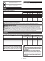
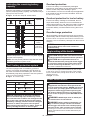
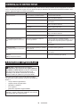
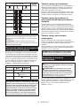
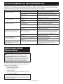
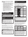
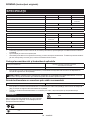
SPECIFICATIONS
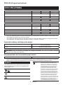
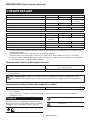
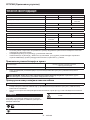
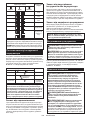
Model: UH004G UH005G UH006G
Blade length 600 mm 750 mm 600 mm
Strokes per minute 2,000 / 3,600 / 5,000 min-1 2,000 / 3,000 /
4,000 min-1
Overall length 1,120 mm 1,263 mm 1,123 mm
Rated voltage D.C. 36 V - 40 V max
Net weight 4.3 - 4.9 kg 4.5 - 5.1 kg 4.4 - 5.0 kg
Protection degree IPX4
Model: UH007G UH008G UH009G
Blade length 750 mm 600 mm 750 mm
Strokes per minute 2,000 / 3,000 /
4,000 min-1 2,000 / 3,600 / 5,000 min-1
Overall length 1,274 mm 1,120 mm 1,262 mm
Rated voltage D.C. 36 V - 40 V max
Net weight 4.6 - 5.2 kg 4.3 - 4.9 kg 4.4 - 5.0 kg
Protection degree IPX4
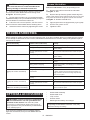
•
Due to our continuing program of research and development, the specications herein are subject to change without notice.
• Specications may dier from country to country.
• The weight may dier depending on the attachment(s), including the battery cartridge. The lightest and heavi-
est combination, according to EPTA-Procedure 01/2014, are shown in the table.
Applicable battery cartridge and charger
Battery cartridge BL4020* / BL4025* / BL4040* / BL4050F
* : Recommended battery
Charger DC40RA / DC40RB / DC40RC
•
Some of the battery cartridges and chargers listed above may not be available depending on your region of residence.
WARNING: Only use the battery cartridges and chargers listed above. Use of any other battery cartridges
and chargers may cause injury and/or re.
Recommended cord connected power source
Portable power pack PDC01 / PDC1200
• The cord connected power source(s) listed above may not be available depending on your region of residence.
• Before using the cord connected power source, read instruction and cautionary markings on them.
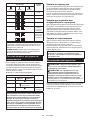
Symbols
The followings show the symbols which may be used
for the equipment. Be sure that you understand their
meaning before use.
Read instruction manual.
Wear eye protection.
DANGER - Keep hands away from blade.
Ni-MH
Li-ion Only for EU countries
Due to the presence of hazardous com-
ponents in the equipment, waste electrical
and electronic equipment, accumulators
and batteries may have a negative impact
on the environment and human health.
Do not dispose of electrical and electronic
appliances or batteries with household waste!
In accordance with the European Directive on
waste electrical and electronic equipment and on
accumulators and batteries and waste accumu-
lators and batteries, as well as their adaptation to
national law, waste electrical equipment, batter-
ies and accumulators should be stored sepa-
rately and delivered to a separate collection point
for municipal waste, operating in accordance with
the regulations on environmental protection.
This is indicated by the symbol of the crossed-
out wheeled bin placed on the equipment.

9ENGLISH
Guaranteed sound power level according
to EU Outdoor Noise Directive.
Sound power level according to Australia
NSW Noise Control Regulation
Intended use
The tool is intended for trimming hedges.
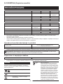
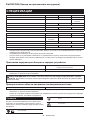
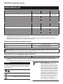
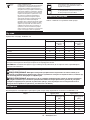
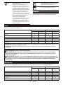
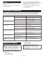
Noise
Applicable standard : EN62841-4-2
Model Sound pressure level Sound power level
LpA(dB(A)) Uncertainty K
(dB(A)) LWA(dB(A)) Uncertainty K
(dB(A))
UH004G 85 396 3
UH005G 86 397 3
UH006G 81 392 3
UH007G 81 392 3
UH008G 82 393 3
UH009G 83 394 3
NOTE: The declared noise emission value(s) has been measured in accordance with a standard test method and
may be used for comparing one tool with another.
NOTE: The declared noise emission value(s) may also be used in a preliminary assessment of exposure.
WARNING: Wear ear protection.
WARNING: The noise emission during actual use of the power tool can dier from the declared val-
ue(s) depending on the ways in which the tool is used especially what kind of workpiece is processed.
WARNING: Be sure to identify safety measures to protect the operator that are based on an estimation
of exposure in the actual conditions of use (taking account of all parts of the operating cycle such as the
times when the tool is switched o and when it is running idle in addition to the trigger time).
Vibration
The vibration total value (tri-axial vector sum) determined according to EN62841-4-2:
Model Front handle Rear handle
ah (m/s2)Uncertainty K
(m/s2)ah (m/s2)Uncertainty K
(m/s2)
UH004G 2.9 1.5 2.0 1.5
UH005G 3.1 1.5 2.7 1.5
UH006G 3.0 1.5 2.4 1.5
UH007G 3.4 1.5 3.1 1.5
UH008G 3.1 1.5 2.4 1.5
UH009G 3.2 1.5 2.5 1.5
NOTE: The declared vibration total value(s) has been
measured in accordance with a standard test method
and may be used for comparing one tool with another.
NOTE: The declared vibration total value(s) may also
be used in a preliminary assessment of exposure.
WARNING: The vibration emission during
actual use of the power tool can dier from the
declared value(s) depending on the ways in which
the tool is used especially what kind of workpiece
is processed.
WARNING: Be sure to identify safety mea-
sures to protect the operator that are based on an
estimation of exposure in the actual conditions of
use (taking account of all parts of the operating
cycle such as the times when the tool is switched
o and when it is running idle in addition to the
trigger time).

10 ENGLISH
EC Declaration of Conformity
For European countries only
The EC declaration of conformity is included as Annex A
to this instruction manual.
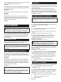
SAFETY WARNINGS
General power tool safety warnings
WARNING: Read all safety warnings, instruc-
tions, illustrations and specications provided
with this power tool. Failure to follow all instructions
listed below may result in electric shock, re and/or
serious injury.
Save all warnings and instruc-
tions for future reference.
The term "power tool" in the warnings refers to your
mains-operated (corded) power tool or battery-operated
(cordless) power tool.
Cordless Hedge Trimmer Safety
Warnings
1. Keep all parts of the body away from the blade.
Do not remove cut material or hold material
to be cut when blades are moving. Blades
continue to move after the switch is turned o. A
moment of inattention while operating the hedge
trimmer may result in serious personal injury.
2. Carry the hedge trimmer by the handle with the
blade stopped and taking care not to operate
any power switch. Proper carrying of the hedge
trimmer will decrease the risk of inadvertent start-
ing and resultant personal injury from the blades.
3. When transporting or storing the hedge trim-
mer, always t the blade cover. Proper handling
of the hedge trimmer will decrease the risk of
personal injury from the blades.
4. When clearing jammed material or servicing
the unit, make sure all power switches are o
and the battery pack is removed or discon-
nected. Unexpected actuation of the hedge trim-
mer while clearing jammed material or servicing
may result in serious personal injury.
5. Hold the hedge trimmer by insulated gripping
surfaces only, because the blade may contact
hidden wiring. Blades contacting a "live" wire
may make exposed metal parts of the hedge trim-
mer "live" and could give the operator an electric
shock.
6. Keep all power cords and cables away from
cutting area. Power cords or cables may be hid-
den in hedges or bushes and can be accidentally
cut by the blade.
7. Do not use the hedge trimmer in bad weather
conditions, especially when there is a risk of
lightning. This decreases the risk of being struck
by lightning.
Additional Safety Instructions
Preparation
1. Check the hedges and bushes for foreign
objects, such as wire fences or hidden wiring
before operating the tool.
2. The tool must not be used by children or
young persons under 18 years of age. Young
persons over 16 years of age may be exempted
from this restriction if they are undergoing training
under the supervision of an expert.
3. First-time users should have an experienced
user show them how to use the tool.
4. Use the tool only if you are in good physical
condition. If you are tired, your attention will be
reduced. Be especially careful at the end of a
working day. Perform all work calmly and carefully.
The user is responsible for all damages to third
parties.
5. Never use the tool when under the inuence of
alcohol, drugs or medication.
6. Work gloves of stout leather are part of the
basic equipment of the tool and must always
be worn when working with it. Also wear
sturdy shoes with anti-skid soles.
7. Before starting work check to make sure that
the tool is in good and safe working order.
Ensure guards are tted properly. The tool
must not be used unless fully assembled.
Operation
1. Hold the tool rmly with both hands when
using the tool.
2. The tool is intended to be used by the operator
at ground level. Do not use the tool on ladders
or any other unstable support.
3. DANGER - Keep hands away from blade.
Contact with blade will result in serious personal
injury.
4. Do not use the tool in the rain or in wet or
very damp conditions. The electric motor is not
waterproof.
5. Make sure you have a secure footing before
starting operation.
6. Do not operate the tool at no-load
unnecessarily.
7. Immediately switch o the tool and remove the
battery cartridge if the shear blades should
come into contact with a fence or other hard
object. Check the blades for damage, and if
damaged, replace the blades immediately.
8. Before checking the shear blades, taking care
of faults, or removing material caught in the
shear blades, always switch o the tool and
remove the battery cartridge.
9. Never point the shear blades to yourself or
others.
10. If the blades stop moving due to the stuck of
foreign objects between the blades during
operation, switch o the tool and remove the
battery cartridge, and then remove the foreign
objects using tools such as pliers. Removing
the foreign objects by hand may cause an injury
for the reason that the blades may move in reac-
tion to removing the foreign objects.

11 ENGLISH
11. Avoid dangerous environment. Don't use the
tool in damp or wet locations or expose it to
rain. Water entering the tool will increase the
risk of electric shock.
12. When you use the tool on muddy ground, wet
slope, or slippery place, pay attention to your
footing.
13. Avoid working in poor environment where
increased user fatigue is expected.
14. Do not use the tool in bad weather where visi-
bility is limited. Failure to do so may cause fall or
incorrect operation due to low visibility.
15. Do not submerge the tool into a puddle.
16. Do not leave the tool unattended outdoors in
the rain.
17. When wet leaves or dirt adhere to the suc-
tion mouth (ventilation window) due to rain,
remove them.
18. Do not use the tool in the snow.
Electrical and battery safety
1. Avoid dangerous environment. Don't use the
tool in dump or wet locations or expose it to
rain. Water entering the tool will increase the risk
of electric shock.
2. Do not dispose of the battery(ies) in a re.
The cell may explode. Check with local codes for
possible special disposal instructions.
3. Do not open or mutilate the battery(ies).
Released electrolyte is corrosive and may cause
damage to the eyes or skin. It may be toxic if
swallowed.
4. Do not charge battery in rain, or in wet
locations.
5. Do not charge the battery outdoors.
6. Do not handle charger, including charger plug,
and charger terminals with wet hands.
7. Do not replace the battery with wet hands.
8. Do not replace the battery in the rain.
9. Do not wet the terminal of battery with liquid
such as water, or submerge the battery. Do not
leave the battery in the rain, nor charge, use,
or store the battery in a damp or wet place. If
the terminal gets wet or liquid enters inside of bat-
tery, the battery may be short circuited and there is
a risk of overheat, re, or explosion.
10. After removing the battery from the tool or
charger, be sure to attach the battery cover to
the battery and store it in a dry place.
11. If the battery cartridge gets wet, drain the
water inside and then wipe it with a dry cloth.
Dry the battery cartridge completely in a dry
place before use.
Maintenance and storage
1. Switch o the tool and remove the battery
cartridge before doing any maintenance work.
2. When moving the tool to another location,
including during work, always remove the
battery cartridge and put the blade cover on
the shear blades. Never carry or transport the
tool with the blades running. Never grasp the
blades with your hands.
3. Clean the tool and especially the shear blades
after use, and before putting the tool into stor-
age for extended periods. Lightly oil the blades
and put on the blade cover.
4. Store the tool with the blade cover on, in a dry
room. Keep it out of reach of children. Never
store the tool outdoors.
5. Do not dispose of the battery(ies) in a re. The
cell may explode. Check with local codes for
possible special disposal instructions.
6. Do not open or mutilate the battery(ies).
Released electrolyte is corrosive and may
cause damage to the eyes or skin. It may be
toxic if swallowed.
7.
Do not charge battery in rain, or in wet locations.
8. Do not wash the tool with high pressure water.
9. When washing the tool, do not let water enter
the electrical mechanism such as battery,
motor, and terminals.
10. Perform inspection or maintenance in a place
where rain can be avoided.
11. After using the tool, remove the adhered dirt
and dry the tool completely before storing.
Depending on the season or the area, there is a
risk of malfunction due to freezing.
12. When storing the tool, avoid direct sunlight
and rain, and store it in a place where it does
not get hot or humid.
SAVE THESE INSTRUCTIONS.
WARNING: DO NOT let comfort or familiarity
with product (gained from repeated use) replace
strict adherence to safety rules for the subject
product. MISUSE or failure to follow the safety
rules stated in this instruction manual may cause
serious personal injury.
Important safety instructions for
battery cartridge
1. Before using battery cartridge, read all instruc-
tions and cautionary markings on (1) battery
charger, (2) battery, and (3) product using
battery.
2. Do not disassemble or tamper the battery
cartridge. It may result in a re, excessive heat,
or explosion.
3. If operating time has become excessively
shorter, stop operating immediately. It may
result in a risk of overheating, possible burns
and even an explosion.
4. If electrolyte gets into your eyes, rinse them
out with clear water and seek medical atten-
tion right away. It may result in loss of your
eyesight.
5. Do not short the battery cartridge:
(1) Do not touch the terminals with any con-
ductive material.
(2) Avoid storing battery cartridge in a con-
tainer with other metal objects such as
nails, coins, etc.
(3) Do not expose battery cartridge to water
or rain.

12 ENGLISH
A battery short can cause a large current
ow, overheating, possible burns and even a
breakdown.
6. Do not store and use the tool and battery car-
tridge in locations where the temperature may
reach or exceed 50 °C (122 °F).
7. Do not incinerate the battery cartridge even if
it is severely damaged or is completely worn
out. The battery cartridge can explode in a re.
8. Do not nail, cut, crush, throw, drop the battery
cartridge, or hit against a hard object to the
battery cartridge. Such conduct may result in a
re, excessive heat, or explosion.
9. Do not use a damaged battery.
10. The contained lithium-ion batteries are subject
to the Dangerous Goods Legislation require-
ments.
For commercial transports e.g. by third parties,
forwarding agents, special requirement on pack-
aging and labeling must be observed.
For preparation of the item being shipped, consult-
ing an expert for hazardous material is required.
Please also observe possibly more detailed
national regulations.
Tape or mask o open contacts and pack up the
battery in such a manner that it cannot move
around in the packaging.
11. When disposing the battery cartridge, remove
it from the tool and dispose of it in a safe
place. Follow your local regulations relating to
disposal of battery.
12. Use the batteries only with the products
specied by Makita. Installing the batteries to
non-compliant products may result in a re, exces-
sive heat, explosion, or leak of electrolyte.
13. If the tool is not used for a long period of time,
the battery must be removed from the tool.
14. During and after use, the battery cartridge may
take on heat which can cause burns or low
temperature burns. Pay attention to the han-
dling of hot battery cartridges.
15. Do not touch the terminal of the tool imme-
diately after use as it may get hot enough to
cause burns.
16. Do not allow chips, dust, or soil stuck into the
terminals, holes, and grooves of the battery
cartridge. It may result in poor performance or
breakdown of the tool or battery cartridge.
17. Unless the tool supports the use near
high-voltage electrical power lines, do not use
the battery cartridge near a high-voltage elec-
trical power lines. It may result in a malfunction
or breakdown of the tool or battery cartridge.
18. Keep the battery away from children.
SAVE THESE INSTRUCTIONS.
CAUTION: Only use genuine Makita batteries.
Use of non-genuine Makita batteries, or batteries that
have been altered, may result in the battery bursting
causing res, personal injury and damage. It will
also void the Makita warranty for the Makita tool and
charger.
Tips for maintaining maximum
battery life
1. Charge the battery cartridge before completely
discharged. Always stop tool operation and
charge the battery cartridge when you notice
less tool power.
2. Never recharge a fully charged battery car-
tridge. Overcharging shortens the battery
service life.
3. Charge the battery cartridge with room tem-
perature at 10 °C - 40 °C (50 °F - 104 °F). Let
a hot battery cartridge cool down before
charging it.
4. When not using the battery cartridge, remove
it from the tool or the charger.
5. Charge the battery cartridge if you do not use
it for a long period (more than six months).
FUNCTIONAL
DESCRIPTION
CAUTION: Always be sure that the tool is
switched o and the battery cartridge is removed
before adjusting or checking function on the tool.
Installing or removing battery
cartridge
CAUTION: Always switch o the tool before
installing or removing of the battery cartridge.
CAUTION: Hold the tool and the battery car-
tridge rmly when installing or removing battery
cartridge. Failure to hold the tool and the battery
cartridge rmly may cause them to slip o your hands
and result in damage to the tool and battery cartridge
and a personal injury.
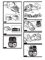
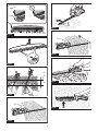
► Fig.1: 1. Red indicator 2. Button 3. Battery cartridge
To remove the battery cartridge, slide it from the tool
while sliding the button on the front of the cartridge.
To install the battery cartridge, align the tongue on the
battery cartridge with the groove in the housing and slip
it into place. Insert it all the way until it locks in place
with a little click. If you can see the red indicator as
shown in the gure, it is not locked completely.
CAUTION: Always install the battery cartridge
fully until the red indicator cannot be seen. If not,
it may accidentally fall out of the tool, causing injury to
you or someone around you.
CAUTION: Do not install the battery cartridge
forcibly. If the cartridge does not slide in easily, it is
not being inserted correctly.

13 ENGLISH
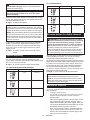
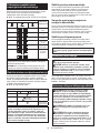
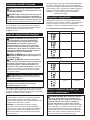
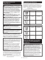
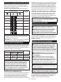
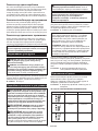
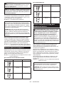
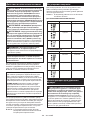
Indicating the remaining battery
capacity
Press the check button on the battery cartridge to indi-
cate the remaining battery capacity. The indicator lamps
light up for a few seconds.
► Fig.2: 1. Indicator lamps 2. Check button
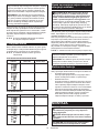
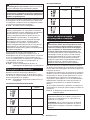
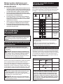
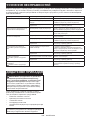
Indicator lamps Remaining
capacity
Lighted O Blinking
75% to 100%
50% to 75%
25% to 50%
0% to 25%
Charge the
battery.
The battery
may have
malfunctioned.
NOTE: Depending on the conditions of use and the
ambient temperature, the indication may dier slightly
from the actual capacity.
NOTE: The rst (far left) indicator lamp will blink when
the battery protection system works.
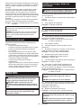
Tool / battery protection system
The tool is equipped with a tool/battery protection
system. This system automatically cuts o power to
the motor to extend tool and battery life. The tool will
automatically stop during operation if the tool is placed
under one of the following conditions:
► Fig.3: 1. Caution lamp
Caution lamp Status
Color On Blinking
Green Overload
Red (tool) / (battery) Overheat
Red Over
discharge
NOTICE: Depending on the usage conditions,
the tool automatically stops without any indica-
tion if the branches or debris are entangled in the
tool. In this case, switch o the tool and remove
the battery cartridge, and then remove entangled
branches or debris using tools such as pliers.
After removing the branches or debris, install the
battery cartridge and turn on the tool again.
Overload protection
If the tool or battery is overloaded by entangled
branches or other debris, the tool automatically stops
and the caution lamp starts blinking in green.
In this situation, turn the tool o and stop the application
that caused the tool to become overloaded. Then turn
the tool on to restart.
Overheat protection for tool or battery
If the tool or battery cartridge is overheated, the tool
stops automatically. When the tool is overheated, the
caution lamp lights up in red. When the battery cartridge
is overheated, the caution lamp blinks in red. Let the
tool and/or battery cool down before turning the tool on
again.
Overdischarge protection
When the battery capacity becomes low, the tool stops
automatically and the caution lamp starts blinking in red.
If the tool does not operate even when the switches are
operated, remove the battery cartridge from the tool and
charge it.
NOTICE: If the tool stops due to a cause
not described above, refer to the section for
troubleshooting.
Angle setting of the handle
CAUTION: Always make sure that the handle
is locked in the desired position before operation.
CAUTION: Do not pull down the lever to
unlock the handle while pulling the switch trigger.
Do not pull the switch trigger while pulling down
the lever and turning the handle. Failure to do so
may cause a malfunction of the tool.
You can set the angle of the handle to 0°, 45°, or 90°
to the left or right. To change the angle of the handle,
turn the handle while pulling down the lever, and then
release the lever.
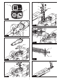
► Fig.4: 1. Lever
Power switch action
WARNING: For your safety, this tool is
equipped with lock-o lever which prevents the
tool from unintended starting. NEVER use the tool
if it runs when you simply press the switch lever
and pull the switch trigger without pressing the
lock-o lever. Return the tool to our authorized
service center for proper repairs BEFORE further
usage.
WARNING: NEVER tape down or defeat pur-
pose and function of lock-o lever.
WARNING: Before installing the battery car-
tridge on the tool, always check to see that the
switch trigger and switch lever actuate properly
and return to the "OFF" position when released.
Operating a tool with a switch that does not actuate
properly can lead to loss of control and serious per-
sonal injury.

14 ENGLISH
CAUTION: Never put your nger on the
switch when carrying. The tool may start uninten-
tionally and cause injury.
NOTICE: Do not pull the switch trigger hard with-
out pressing the lock-o lever. This can cause
switch breakage.
Press the main power button to turn on the tool. To turn
o the tool, press and hold the main power button until
the speed indicators go o.
► Fig.5: 1. Main power button
NOTE: The caution lamp brinks if the switch trigger
is pulled under unoperatable conditions. The caution
lamp blinks if you turn on the main power switch while
holding down the lock-o lever and the switch trigger.
NOTE: This tool employs the auto power-o function.
To avoid unintentional start up, the main power switch
will automatically shut down when the switch trigger
is not pulled for a certain period after the main power
switch is turned on.
To prevent the switch trigger from being accidentally
pulled, a lock-o lever is provided. To start the tool,
depress the lock-o lever, and then press the switch
lever and pull the switch trigger. Release the switch
trigger to stop.
► Fig.6: 1. Switch lever 2. Lock-o lever 3. Switch
trigger
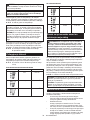
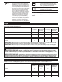
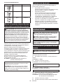
Speed adjusting
You can select the tool speed by tapping the main
power button. Each time you tap the main power button,
the level of speed will change.
► Fig.7: 1. Speed indicator 2. Main power button
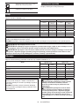
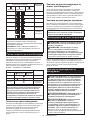
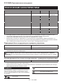
For UH004G/UH005G/UH008G/UH009G
Indicator Mode Stroke speed
High 5,000 min-1
Medium 3,600 min-1
Low 2,000 min-1
For UH006G/UH007G
Indicator Mode Stroke speed
High 4,000 min-1
Medium 3,000 min-1
Low 2,000 min-1
Reverse button for debris removal
WARNING:
If the entangled branches or debris
cannot be removed by the reverse function, switch o
the tool and remove the battery cartridge, and then
remove the entangled branches or debris using tools
such as pliers. Failure to switch o the tool and remove
the battery cartridge may result in serious personal
injury from accidental start-up. Removing the entangled
branches or debris by hand may cause an injury, since
the shear blades may move in reaction to removing them.
This tool has a reverse button to change the direction
of shear blades movement. It is only for removing
branches and debris entangled in the tool.
To reverse the shear blades movement, tap the reverse
button when the shear blades have stopped, then press
the switch lever and pull the switch trigger while press-
ing the lock-o lever. The speed indicators start blink-
ing, and the shear blades move in reverse direction.
To return to regular movement, release the trigger and
wait until the shear blades stop.
► Fig.8: 1. Speed indicator 2. Reverse button
NOTE:
If the entangled branches or debris cannot be removed,
release and pull the switch trigger until they are removed.
NOTE: If you tap the reverse button while the shear
blades are still moving, the tool comes to stop and to
be ready for reverse movement.
Electronic function
The tool is equipped with the electronic functions for
easy operation.
• Constant speed control
The speed control function provides the constant
rotation speed regardless of load conditions.
• Electric brake
This tool is equipped with an electric brake. If the
tool consistently fails to quickly stop the shear
blades after releasing the switch trigger, have the
tool serviced at Makita Authorized Service Center.
• Accidental re-start preventive function
Even if you install the battery cartridge while pull-
ing the switch trigger, the tool does not start. To
start the tool, rst release the switch trigger, and
then pull the switch trigger.

15 ENGLISH
ASSEMBLY
CAUTION: Always be sure that the tool is
switched o and the battery cartridge is removed
before carrying out any work on the tool.
CAUTION: When replacing the shear blades,
always wear gloves so that your hands do not
directly contact the blades.
NOTICE: When replacing the shear blades, do
not wipe o grease from the gear and crank.
Installing or removing the shear
blades
CAUTION: Attach the blade cover before
removing or installing the shear blades.
You can install 600 mm or 750 mm shear blades to your
tool.
1.
Place the tool upside down, and then remove 6 bolts.
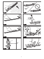
► Fig.9: 1. Bolt
2. Remove the cover and the plate.
► Fig.10: 1. Cover 2. Plate
NOTE: The plate may remain on the cover.
3. Remove the rod and the bearing.
► Fig.11: 1. Rod 2. Bearing
NOTE: The rod may remain on the cover.
4. Remove 2 bolts, the felt pad and the sleeves, and
then remove the shear blades.
► Fig.12: 1. Felt pad 2. Bolt 3. Sleeve 4. Shear blades
5. Remove the blade cover.
6. Attach the blade cover to the new shear blades.
7. Adjust the crank so that 2 holes are lined up on
the alignment line.
► Fig.13: 1. Hole 2. Alignment line
8. Align the protrusions on the shear blades vertically
at the same position.
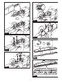
► Fig.14: 1. Protrusion
9. Attach the felt pad to the shear blades.
► Fig.15: 1. Felt pad
10. Insert the protrusion on the shear blades to the
small hole on the rod, then align the position of the felt
pad with the holes on the tool, and then attach new
sleeves.
► Fig.16: 1. Protrusion 2. Small hole 3. Sleeve 4. Felt
pad
NOTICE: Apply a small amount of grease to the
inner periphery of the hole of the rod.
NOTICE: Be careful not to lose the sleeves.
11. Align the holes on the shear blades with the holes
on the tool, and then tighten 2 bolts to x the shear
blades.
► Fig.17: 1. Bolt 2. Hole
12. Attach the bearing and the rod.
► Fig.18: 1. Rod 2. Small hole 3. Bearing
NOTICE: Apply a small amount of grease to the
inner periphery of the small hole of the rod.
NOTICE: Make sure that the protrusion on the
shear blades ts in the small hole on the rod.
13. Attach the plate.
► Fig.19: 1. Protrusion 2. Plate
NOTICE: Make sure that the protrusion on the
shear blades ts in the hole on the plate.
14. Attach the cover, and then tighten 6 bolts.
► Fig.20: 1. Bolt 2. Cover
NOTICE: If the shear blades do not move
smoothly, the shear blades are not engaged with
the rods properly. Install the shear blades again.
NOTICE: If the parts other than the shear
blades such as the rods are worn out, ask Makita
Authorized Service Centers for parts replacement
or repairs.
Installing or removing the chip receiver
Optional accessory
CAUTION: When installing or removing the
chip receiver, always wear gloves so that your
hands do not directly contact the shear blades.
NOTICE:
For UH004G/UH005G/UH006G/UH007G
The blade cover cannot be installed if the chip
receiver is installed on the tool. Before carrying or
storing the tool, uninstall the chip receiver, and then
install the blade cover to avoid blade exposure.
NOTICE:
For UH004G/UH005G/UH006G/UH007G
Be sure to remove the blade cover before install-
ing the chip receiver.
The chip receiver gathers discarded leaves and makes
clean-up afterward much easier. It can be installed on
either side of the tool.
1.
Hook the claws of the chip receiver to the shear blades.
► Fig.21: 1. Claw
2. Align the holes on the chip receiver with the
screws on the shear blades, and then attach the chip
receiver to the shear blades securely.
► Fig.22: 1. Hole
NOTICE: Make sure that the chip receiver does
not overlap the branch catcher.
► Fig.23: 1. Branch catcher
To remove the chip receiver, press the levers to release
the claws.
► Fig.24: 1. Lever
NOTICE: Never try to remove the chip receiver
by an excessive force with its hooks locked to the
shear blades.

16 ENGLISH
OPERATION
WARNING: Keep hands away from shear
blades.
CAUTION: Avoid operating the tool in very
hot weather as much as practicable. When operat-
ing the tool, be careful of your physical condition.
CAUTION: Be careful not to accidentally
contact a metal fence or other hard objects while
trimming. The shear blades may break and cause
an injury.
CAUTION: Be careful not to allow the shear
blades to contact the ground. The tool may recoil
and cause an injury.
CAUTION: Overreaching with a hedge trim-
mer, particularly from a ladder, is extremely
dangerous. Do not work while standing on anything
wobbly or inrm.
NOTICE: Do not attempt to cut branches thicker
than 10 mm in diameter with the tool. Cut branches
to 10 cm lower than the cutting height using branch
cutters before using the tool.
► Fig.25: (1) Cutting height (2) 10 cm
NOTICE: Do not cut down dead trees or similar
hard objects. Doing so may damage the tool.
NOTICE: Do not trim the grass or weeds while
using the shear blades. The shear blades may
become tangled in the grass or weeds.
Hold the tool with both hands, press the switch lever
and pull the switch trigger while pressing the lock-o
lever, and then move it forward.
► Fig.26
For basic operation, tilt the shear blades toward the
trimming direction and move it calmly and slowly at the
speed rate of 3 to 4 seconds per meter.
► Fig.27
To cut a hedge top evenly, tie a string at the desired
height and trim along it.
► Fig.28
If the chip receiver is attached to the shear blades, it
gathers discarded leaves and makes clean-up after-
ward much easier.
► Fig.29
To cut a hedge side evenly, cut from the bottom to top.
► Fig.30
When trimming to make a round shape (trimming box-
wood or rhododendron, etc.), trim from the root to the
top for a beautiful nish.
► Fig.31
MAINTENANCE
CAUTION:
Always be sure that the tool is
switched o and the battery cartridge is removed before
attempting to perform inspection or maintenance.
To maintain product SAFETY and RELIABILITY,
repairs, any other maintenance or adjustment should
be performed by Makita Authorized or Factory Service
Centers, always using Makita replacement parts.
Cleaning the tool
Clean the tool by wiping o dust with a dry cloth or one
dipped in soapy water and wrung out.
NOTICE: Never use gasoline, benzine, thinner,
alcohol or the like. Discoloration, deformation or
cracks may result.
Shear blade maintenance
Before the operation or once per hour during operation,
apply low-viscosity oil (machine oil, or spray-type lubri-
cating oil) to the shear blades.
► Fig.32
After operation, remove dust from both sides of the shear blades
with a wired brush, wipe it o with a cloth and then apply low-viscos-
ity oil (machine oil, or spray-type lubricating oil) to the shear blades.
► Fig.33
NOTICE: Do not wash the shear blades in water.
Doing so may cause rust or damage to the tool.
NOTICE: Dirt and corrosion cause excessive
blade friction and shorten the operating time per
battery charge.
Storage
The hook hole in the tool bottom is convenient for hang-
ing the tool from a nail or screw on the wall.
Attach the blade cover to the shear blades so that the blades
are not exposed. Store the tool out of the reach of children.
Store the tool in a place not exposed to moisture or rain.
► Fig.34: 1. Hole
Grinding the shear blades
NOTICE:
If the shear blades have considerably deformed
by grinding, replace the shear blades with new ones.
1. Install the battery cartridge to the tool.
2. Turn on and start the tool so that the upper blade
and lower blade are positioned alternately.
► Fig.35
3.
Turn o the tool and remove the battery cartridge from the tool.
4.
Remove the screw, and then remove the branch catcher.
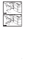
► Fig.36: 1. Screw 2. Branch catcher
5.
Set the angle of a le to 45° (for UH004G/UH005G/
UH008G/UH009G) or 50° (for UH006G/UH007G), and
grind the upper blade from 3 directions with the le.
► Fig.37: (1) File (2) 45° or 50°

17 ENGLISH
CAUTION: Before grinding the shear blades,
make sure that the tool is switched o and the
battery cartridge is removed from the tool.
6. Place the tool upside down, and then remove the
burrs from the shear blades with the dressing stone.
► Fig.38: 1. Dressing stone
7.
Set the angle of the le to 45° (for UH004G/UH005G/
UH008G/UH009G) or 50° (for UH006G/UH007G), and grind
the lower blade from 3 directions with the le.
8.
Return the tool to normal position, and then remove
the burrs from the shear blades with the dressing stone.
9. Attach the branch catcher by tightening the screw.
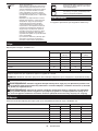
Grease lubrication
Interval of lubrication: Every 50 operating hours
1. Remove the bolt from the hole for lubrication.
► Fig.39: 1. Bolt
2.
Remove the cap from the grease vessel. Align the
outlet of the grease vessel with the hole on the cover, and
then press the outlet of the grease vessel onto the hole.
► Fig.40: 1. Grease vessel 2. Hole
3.
Apply the grease to the tool (Approximately 5 g as a guide).
4. Remove the grease vessel.
5. Tighten the bolt.
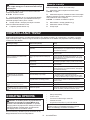
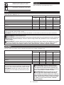
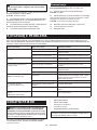
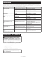
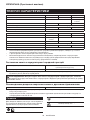
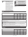
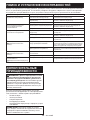
TROUBLESHOOTING
Before asking for repairs, conduct your own inspection rst. If you nd a problem that is not explained in the manual,
do not attempt to dismantle the tool. Instead, ask Makita Authorized Service Centers, always using Makita replace-
ment parts for repairs.
State of abnormality Probable cause (malfunction) Remedy
Motor does not run. Battery cartridge is not installed. Install the battery cartridge.
Battery problem (under voltage) Recharge the battery. If recharging is not eective,
replace battery.
The drive system does not work
correctly. Ask your local authorized service center for repair.
Motor stops running after a little use. Battery's charge level is low. Recharge the battery. If recharging is not eective,
replace battery.
Overheating. Stop using of tool to allow it to cool down.
Tool does not reach maximum RPM. Battery is installed improperly. Install the battery cartridge as described in this
manual.
Battery power is dropping. Recharge the battery. If recharging is not eective,
replace battery.
The drive system does not work correctly.
Ask your local authorized service center for repair.
Shear blades do not move:
stop the machine immediately!
Foreign objects are caught between the
shear blades. 1. Use the reverse button.
2. Switch o the tool and remove the battery car-
tridge, and then remove the foreign objects using
tools such as pliers.
The drive system does not work
correctly. Ask your local authorized service center for repair.
Abnormal vibration:
stop the machine immediately!
Shear blades are broken, bent or worn. Replace the shear blades.
The drive system does not work
correctly. Ask your local authorized service center for repair.
Shear blades and motor cannot stop:
Remove the battery immediately!
Electric malfunction. Remove the battery and ask your local authorized
service center for repair.
OPTIONAL ACCESSORIES
CAUTION: These accessories or attachments
are recommended for use with your Makita tool
specied in this manual. The use of any other
accessories or attachments might present a risk of
injury to persons. Only use accessory or attachment
for its stated purpose.
If you need any assistance for more details regard-
ing these accessories, ask your local Makita Service
Center.
• Shear blade assembly
• Shear blade cover
• Chip receiver
• Grease vessel
• Makita genuine battery and charger
NOTE: Some items in the list may be included in the
tool package as standard accessories. They may
dier from country to country.

18 SLOVENŠČINA
SLOVENŠČINA (Originalna navodila)
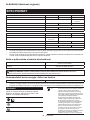
TEHNIČNI PODATKI
Model: UH004G UH005G UH006G
Dolžina rezila 600 mm 750 mm 600 mm
Hodi na minuto 2.000/3.600/5.000 min-1 2.000/3.000/
4.000 min-1
Celotna dolžina 1.120 mm 1.263 mm 1.123 mm
Nazivna napetost D.C. 36 V – 40 V
Neto teža 4,3 – 4,9 kg 4,5 – 5,1 kg 4,4 – 5,0 kg
Stopnja zaščite IPX4
Model: UH007G UH008G UH009G
Dolžina rezila 750 mm 600 mm 750 mm
Hodi na minuto 2.000/3.000/
4.000 min-1 2.000/3.600/5.000 min-1
Celotna dolžina 1.274 mm 1.120 mm 1.262 mm
Nazivna napetost D.C. 36 V – 40 V
Neto teža 4,6 – 5,2 kg 4,3 – 4,9 kg 4,4 – 5,0 kg
Stopnja zaščite IPX4
• Ker nenehno opravljamo raziskave in razvijamo svoje izdelke, se lahko tehnični podatki v tem dokumentu
spremenijo brez obvestila.
• Tehnični podatki se lahko razlikujejo od države do države.
• Teža se lahko razlikuje glede na priključke, vključno z akumulatorsko baterijo. Najlažja in najtežja kombinacija v
skladu s postopkom EPTA 01/2014 sta prikazani v preglednici.
Uporabna akumulatorska baterija in polnilnik
Baterijski vložek BL4020* / BL4025* / BL4040* / BL4050F
* : Priporočeni akumulator
Polnilnik DC40RA / DC40RB / DC40RC
• Nekatere zgoraj navedene akumulatorske baterije in polnilniki morda v vaši državi prebivališča niso na voljo.
OPOZORILO: Uporabljajte le zgoraj navedene akumulatorske baterije in polnilnike. Uporaba drugih
akumulatorskih baterij in polnilnikov lahko povzroči telesne poškodbe in/ali požar.
Priporočen vir napajanja s kablom
Prenosna polnilna enota PDC01 / PDC1200
• Vir(i) napajanja s kablom, navedeni zgoraj, morda v vaši državi prebivališča niso na voljo.
• Pred uporabo vira napajanja s kablom preberite navodila in opozorilne znake na njem.
Simboli
Naslednji simboli se lahko uporabljajo v povezavi s
strojem. Pred uporabo izdelka se obvezno seznanite z
njihovim pomenom.
Preberite navodila za uporabo.
Uporabljajte zaščito za oči.
NEVARNOST – z rokami ne segajte v
območje rezila.
Ni-MH
Li-ion Samo za države EU
Zaradi prisotnosti nevarnih komponent v
opremi imajo lahko uporabljena električna
in elektronska oprema, akumulatorji in bate-
rije negativen vpliv na okolje in zdravje ljudi.
Električnih in elektronskih naprav ali baterij
ne odlagajte med gospodinjske odpadke!
Skladno z evropsko Direktivo o odpadni
električni in elektronski opremi, o akumula-
torjih in baterijah ter odpadnih akumulator-
jih in baterijah ter njeno uporabo v državnih
zakonih morate rabljeno električno in
elektronsko opremo, baterije in akumula-
torje zbirati ločeno ter dostaviti na posebno
zbiralno mesto za komunalne odpadke, ki
deluje skladno s predpisi za zaščito okolja.
To nakazuje simbol prečrtanega smetnjaka
s kolesi, ki je natisnjen na opremi.

19 SLOVENŠČINA
Zajamčena raven zvočne moči v skladu z
direktivo EU o hrupu na prostem.
Raven zvočne moči v skladu z avstralskim
predpisom o nadzoru hrupa NSW
Predvidena uporaba
Orodje je namenjeno rezanju žive meje.
Hrup
Veljavni standard : EN62841-4-2
Model Raven zvočnega tlaka Raven zvočne moči
LpA(dB(A)) Odstopanje K
(dB(A)) LWA(dB(A)) Odstopanje K
(dB(A))
UH004G 85 396 3
UH005G 86 397 3
UH006G 81 392 3
UH007G 81 392 3
UH008G 82 393 3
UH009G 83 394 3
OPOMBA: Navedene vrednosti oddajanja hrupa so bile izmerjene v skladu s standardnimi metodami testiranja in
se lahko uporabljajo za primerjavo orodij.
OPOMBA: Navedene vrednosti oddajanja hrupa se lahko uporabljajo tudi pri predhodni oceni izpostavljenosti.
OPOZORILO: Uporabljajte zaščito za sluh.
OPOZORILO: Oddajanje hrupa med dejansko uporabo električnega orodja se lahko razlikuje od nave-
denih vrednosti, odvisno od načina uporabe orodja in predvsem vrste obdelovanca.
OPOZORILO: Upravljavec mora za lastno zaščito poznati varnostne ukrepe, ki temeljijo na oceni izpo-
stavljenosti v dejanskih pogojih uporabe (poleg časa proženja je treba upoštevati celoten delovni cikel,
vključno s časom, ko je orodje izklopljeno, in časom, ko deluje v prostem teku).
Vibracije
Skupne vrednosti vibracij (vektorska vsota treh osi) v skladu z EN62841-4-2:
Model Sprednji ročaj Zadnji ročaj
ah (m/s2)Odstopanje K
(m/s2)ah (m/s2)Odstopanje K
(m/s2)
UH004G 2,9 1,5 2,0 1,5
UH005G 3,1 1,5 2,7 1,5
UH006G 3,0 1,5 2,4 1,5
UH007G 3,4 1,5 3,1 1,5
UH008G 3,1 1,5 2,4 1,5
UH009G 3,2 1,5 2,5 1,5
OPOMBA: Navedene skupne vrednosti oddajanja
vibracij so bile izmerjene v skladu s standardnimi
metodami testiranja in se lahko uporabljajo za primer-
javo orodij.
OPOMBA: Navedene skupne vrednosti oddajanja
vibracij se lahko uporabljajo tudi pri predhodni oceni
izpostavljenosti.
OPOZORILO: Oddajanje vibracij med
dejansko uporabo električnega orodja se lahko
razlikuje od navedenih vrednosti, odvisno
od načina uporabe orodja in predvsem vrste
obdelovanca.
OPOZORILO: Upravljavec mora za lastno
zaščito poznati varnostne ukrepe, ki temeljijo
na oceni izpostavljenosti v dejanskih pogojih
uporabe (poleg časa proženja je treba upoštevati
celoten delovni cikel, vključno s časom, ko je
orodje izklopljeno, in časom, ko deluje v prostem
teku).

20 SLOVENŠČINA
Izjava o skladnosti ES
Samo za evropske države
Izjava ES o skladnosti je vključena v dodatku A, ki je
priložen tem navodilom za uporabo.
VARNOSTNA OPOZORILA
Splošna varnostna opozorila za
električno orodje
OPOZORILO: Preberite vsa varnostna opo-
zorila in navodila s slikami in tehničnimi podatki,
ki so dobavljeni skupaj z električnim orodjem.
Ob neupoštevanju spodaj navedenih navodil obstaja
nevarnost električnega udara, požara in/ali hudih
telesnih poškodb.
Shranite vsa opozorila in navo-
dila za poznejšo uporabo.
Izraz „električno orodje“ v opozorilih se nanaša na vaše
električno orodje (s kablom) ali baterijsko električno
orodje (brez kabla).
Varnostna opozorila za brezžični
rezalnik za živo mejo
1. Ne približujte delov telesa rezilu. Ne odstra-
njujte odrezanega materiala in ne držite mate-
riala, ki ga boste rezali, kadar se rezila premi-
kajo. Ko izključite stikalo, se rezila še vedno vrtijo.
Trenutek nepazljivosti pri delu s škarjami za živo
mejo lahko privede do hudih telesnih poškodb.
2. Škarje za živo mejo nosite za ročaj, rezilo mora
biti ustavljeno, bodite pozorni, da ne vklopite
stikala. Če boste škarje za živo mejo pravilno
nosili, boste zmanjšali tveganje za nehoteni zagon
in posledično telesno poškodbo z rezili.
3. Kadar prenašate ali shranjujete škarje za živo
mejo, vedno namestite pokrov rezila. Ustrezno
rokovanje s škarjami za živo mejo bo zmanjšalo
morebitne telesne poškodbe zaradi rezil.
4. Ko odstranjujete zataknjeni material ali
popravljate enoto, se prepričajte, da so vsi
gumbi za vklop/izklop izklopljeni in da je aku-
mulatorska baterija odstranjena ali izklopljena.
Nepričakovan zagon škarij za živo mejo med
čiščenjem zataknjenega materiala ali popravlja-
njem lahko povzroči resne telesne poškodbe.
5.
Držite škarje za živo mejo na izoliranih držalnih
površinah, saj lahko rezilo prereže skrito električno
napeljavo. Ob stiku rezil z vodniki pod napetostjo dobijo
napetost vsi neizolirani kovinski deli škarij za živo mejo,
zaradi česar lahko uporabnik utrpi električni udar.
6.
Električne kable odstranite z območja rezanja.
Med uporabo so lahko kabli skriti živi meji ali grmovju
in jih lahko z rezilom nenamerno prerežete.
7. Škarij za živo mejo ne uporabljajte ob slabem
vremenu, še posebej, kadar bliska. S tem
zmanjšate tveganje, da bi vas zadela strela.
Dodatna varnostna navodila
Priprava
1. Pred uporabo orodja preverite, da v živi meji
in grmičevju ni tujkov, kot so žične ograje ali
skrite žice.
2. Orodja ne smejo uporabljati otroci ali mlajši
od 18 let. Mladoletne osebe, starejše od 16 let,
so lahko izvzete iz te omejitve, če se usposabljajo
pod nadzorom strokovnjaka.
3. Uporabnike, ki prvič uporabljajo orodje, naj
izkušeni uporabnik pouči o uporabi orodja.
4. Orodje uporabljajte samo, če ste dobro zično
pripravljeni. Če ste utrujeni, bo vaša zbranost
zmanjšana. Še posebej bodite pozorni ob koncu
delovnega dne. Vsa dela opravljajte mirno in
zbrano. Uporabnik je odgovoren za vse poškodbe,
povzročene tretjim osebam.
5. Nikoli ne uporabljajte orodja pod vplivom
alkohola, drog ali zdravil.
6. Delovne rokavice iz robustnega usnja so del
osnovne opreme orodja in jih je pri delu treba
vedno nositi. Prav tako nosite močne čevlje z
nedrsečim podplatom.
7. Pred začetkom dela se prepričajte, da je
orodje v dobrem stanju in varno za delo.
Zagotovite, da so ščitniki pravilno nameščeni.
Orodja ni dovoljeno uporabljati, če ni v celoti
sestavljeno.
Uporaba
1.
Med uporabo trdno držite orodje z obema rokama.
2. Orodje je namenjeno uporabi na tleh. Orodja
ne uporabljajte na lestvah ali drugih nestabil-
nih oporah.
3. NEVARNOST - Ne približujte rok rezilu. Stik z
rezilom povzroči hude telesne poškodbe.
4. Orodja ne uporabljajte v dežju ali v zelo vlažnih
pogojih. Električni motor ni vodotesen.
5.
Pred začetkom uporabe zagotovite trdno stojišče.
6. Ne uporabljajte orodja brez obremenitve po
nepotrebnem.
7. Če rezila škarij pridejo v stik z ograjo ali dru-
gim trdim predmetom, takoj ugasnite orodje in
odstranite akumulatorsko baterijo. Preverite
rezila, ali so poškodovana, in jih v tem primeru
takoj zamenjajte.
8. Preden rezila škarij pregledate, odpravite
napake ali odstranite material, ki se je ujel v
rezila škarij, vedno izklopite orodje in odstra-
nite akumulatorsko baterijo.
9. Rezil nikoli ne usmerite proti sebi ali drugim
osebam.
10. Če se med delovanjem rezila nehajo premikati,
ker so se med njih zataknili tujki, izklopite
orodje, odstranite akumulatorsko baterijo in
nato odstranite tujke z orodjem, kot so klešče.
Odstranjevanje tujkov z rokami lahko povzroči
poškodbe, saj se zaradi odstranjevanja tujkov
lahko premaknejo rezila.
11. Izogibajte se nevarnemu okolju. Orodja ne
uporabljajte na vlažnih ali mokrih mestih in
ga ne izpostavljajte dežju. Voda, ki prodre v
orodje, bo povečala nevarnost električnega
udara.
Pagina se încarcă...
Pagina se încarcă...
Pagina se încarcă...
Pagina se încarcă...
Pagina se încarcă...
Pagina se încarcă...
Pagina se încarcă...
Pagina se încarcă...
Pagina se încarcă...
Pagina se încarcă...
Pagina se încarcă...
Pagina se încarcă...
Pagina se încarcă...
Pagina se încarcă...
Pagina se încarcă...
Pagina se încarcă...
Pagina se încarcă...
Pagina se încarcă...
Pagina se încarcă...
Pagina se încarcă...
Pagina se încarcă...
Pagina se încarcă...
Pagina se încarcă...
Pagina se încarcă...
Pagina se încarcă...
Pagina se încarcă...
Pagina se încarcă...
Pagina se încarcă...
Pagina se încarcă...
Pagina se încarcă...
Pagina se încarcă...
Pagina se încarcă...
Pagina se încarcă...
Pagina se încarcă...
Pagina se încarcă...
Pagina se încarcă...
Pagina se încarcă...
Pagina se încarcă...
Pagina se încarcă...
Pagina se încarcă...
Pagina se încarcă...
Pagina se încarcă...
Pagina se încarcă...
Pagina se încarcă...
Pagina se încarcă...
Pagina se încarcă...
Pagina se încarcă...
Pagina se încarcă...
Pagina se încarcă...
Pagina se încarcă...
Pagina se încarcă...
Pagina se încarcă...
Pagina se încarcă...
Pagina se încarcă...
Pagina se încarcă...
Pagina se încarcă...
Pagina se încarcă...
Pagina se încarcă...
Pagina se încarcă...
Pagina se încarcă...
Pagina se încarcă...
Pagina se încarcă...
Pagina se încarcă...
Pagina se încarcă...
Pagina se încarcă...
Pagina se încarcă...
Pagina se încarcă...
Pagina se încarcă...
Pagina se încarcă...
Pagina se încarcă...
Pagina se încarcă...
Pagina se încarcă...
Pagina se încarcă...
Pagina se încarcă...
Pagina se încarcă...
Pagina se încarcă...
Pagina se încarcă...
Pagina se încarcă...
Pagina se încarcă...
Pagina se încarcă...
Pagina se încarcă...
Pagina se încarcă...
Pagina se încarcă...
Pagina se încarcă...
Pagina se încarcă...
Pagina se încarcă...
Pagina se încarcă...
Pagina se încarcă...
Pagina se încarcă...
Pagina se încarcă...
Pagina se încarcă...
Pagina se încarcă...
Pagina se încarcă...
Pagina se încarcă...
Pagina se încarcă...
Pagina se încarcă...
Pagina se încarcă...
Pagina se încarcă...
Pagina se încarcă...
Pagina se încarcă...
-
 1
1
-
 2
2
-
 3
3
-
 4
4
-
 5
5
-
 6
6
-
 7
7
-
 8
8
-
 9
9
-
 10
10
-
 11
11
-
 12
12
-
 13
13
-
 14
14
-
 15
15
-
 16
16
-
 17
17
-
 18
18
-
 19
19
-
 20
20
-
 21
21
-
 22
22
-
 23
23
-
 24
24
-
 25
25
-
 26
26
-
 27
27
-
 28
28
-
 29
29
-
 30
30
-
 31
31
-
 32
32
-
 33
33
-
 34
34
-
 35
35
-
 36
36
-
 37
37
-
 38
38
-
 39
39
-
 40
40
-
 41
41
-
 42
42
-
 43
43
-
 44
44
-
 45
45
-
 46
46
-
 47
47
-
 48
48
-
 49
49
-
 50
50
-
 51
51
-
 52
52
-
 53
53
-
 54
54
-
 55
55
-
 56
56
-
 57
57
-
 58
58
-
 59
59
-
 60
60
-
 61
61
-
 62
62
-
 63
63
-
 64
64
-
 65
65
-
 66
66
-
 67
67
-
 68
68
-
 69
69
-
 70
70
-
 71
71
-
 72
72
-
 73
73
-
 74
74
-
 75
75
-
 76
76
-
 77
77
-
 78
78
-
 79
79
-
 80
80
-
 81
81
-
 82
82
-
 83
83
-
 84
84
-
 85
85
-
 86
86
-
 87
87
-
 88
88
-
 89
89
-
 90
90
-
 91
91
-
 92
92
-
 93
93
-
 94
94
-
 95
95
-
 96
96
-
 97
97
-
 98
98
-
 99
99
-
 100
100
-
 101
101
-
 102
102
-
 103
103
-
 104
104
-
 105
105
-
 106
106
-
 107
107
-
 108
108
-
 109
109
-
 110
110
-
 111
111
-
 112
112
-
 113
113
-
 114
114
-
 115
115
-
 116
116
-
 117
117
-
 118
118
-
 119
119
-
 120
120


Makita UH004G Manual de utilizare
- Categorie
- Aparate de tuns gard viu
- Tip
- Manual de utilizare
Lucrări înrudite
-
Makita DUN461W Manual de utilizare
-
Makita DUM166 Manual de utilizare
-
Makita UH013G Manual de utilizare
-
Makita DUH506 Manual de utilizare
-
Makita EN402MP Manual de utilizare
-
Makita DUN600L Manual de utilizare
-
-
Makita DUH502 Manual de utilizare
-
Makita UH014 Manual de utilizare
-
Makita DUH604S Manual de utilizare