Makita DUM166 Manual de utilizare
- Categorie
- Aparate de tuns gard viu
- Tip
- Manual de utilizare
Acest manual este potrivit și pentru

1
GB
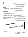
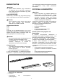
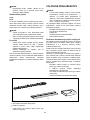
Cordless Grass Shear INSTRUCTION MANUAL
UA
Акумуляторні ножиці для підрізання трави
ІНСТРУКЦІЯ З ЕКСПЛУАТАЦІЇ
PL
Akumulatorowe nożyce do trawy INSTRUKCJA OBSŁUGI
RO
Foarfece de iarbă fără cablu MANUAL DE INSTRUCŢIUNI
DE
Akku-Grasschere BEDIENUNGSANLEITUNG
HU
Vezeték nélküli fűnyíró HASZNÁLATI KÉZIKÖNYV
SK
Akumulátorové nožnice na trávu NÁVOD NA OBSLUHU
CZ
Akumulátorové nůžky na trávu NÁVOD K OBSLUZE
DUM166
DUM168

2
1
2
3
1 012522
1
2 012128
1
2
3 015659
1
2
4 012524
1
5 012523
1
2
3
6 012527
1
2
3
7 012526
8 012525
1
2
9 012528
1
2
3
10 012529
1
11 012533
1
2
3
4
12 012535

3
1
2
3
13 012536
12 3
14 012537
1
2
15 012538
1
2
16 012539
1
2
3
4
17 012540
1
2
3
18 012541
19 012542
1
2
20 012534 21 012543

4
25 012532
1
26 012546
1
27 012545
1
2
22 012544 23 012530 24 012531
1
2
3
28 012561
1
2
29 012539
1
2
3
4
30 012540
1
2
3
31 012562
1
32 012563
1
33 012564

5
1
2
37 012544
1
38 012555
1
2
3
4
39 012557
1
40 012558
1
41 012559
1
2
42 012560
1
2
3
43 011045 44 010878 45 013054
1
34 012565
1
2
35 012554
36 012556

6
49 013056
50 013057
1
2
3
4
51 012547
1
52 012566
1
2
3
46 012550
1
47 013055
48 013053

7
ENGLISH (Original instructions)
Explanation of general view
1-1. Red indicator
1-2. Button
1-3. Battery cartridge
2-1. Star marking
3-1. Indicator lamps
3-2. Check button
4-1. Lock-off button
4-2. Switch trigger
5-1. Indication lamp
6-1. Change lever
6-2. Protrusion on base frame
6-3. Base frame
7-1. Shear blades
7-2. Blade cover
7-3. Blade frame
9-1. Groove
9-2. Base frame
10-1. Change lever
10-2. Protrusion on base frame
10-3. Base frame
11-1. Blade cover
12-1. Locking lever
12-2. Undercover
12-3. Press
12-4. Turn
13-1. Undercover
13-2. Shear blade
13-3. Crank
14-1. Crank
14-2. Undercover
14-3. Shear blades
15-1. Blade cover
15-2. Shear blades
16-1. Basic alignment line on the tool
housing
16-2. Pins
17-1. Recessed part of crank
17-2. Crank
17-3. Apply grease
17-4. Pins
18-1. Base plate
18-2. Hole in the base plate of shear
blades
18-3. Oval holes that are overlapped
20-1. Undercover
20-2. Locking lever
22-1. Groove in the undercover
22-2. Locking lever
26-1. Brush
27-1. Machine oil
28-1. Crank
28-2. Undercover
28-3. Shear blades
29-1. Basic alignment line on the tool
housing
29-2. Pins
30-1. Recessed part of crank
30-2. Crank
30-3. Apply grease
30-4. Pins
31-1. Base plate
31-2. Oval holes that are overlapped
31-3. Hole in the base plate of shear
blades
32-1. Blade cover
33-1. Bent part of the base plate of shear
blades
34-1. Screws
35-1. Locking lever
35-2. Undercover
37-1. Groove in the undercover
37-2. Locking lever
38-1. Blade cover
39-1. Locking lever
39-2. Undercover
39-3. Press
39-4. Turn
40-1. Undercover
41-1. Screws
42-1. Crank
42-2. Shear blades
43-1. Grass shear blade cover
43-2. Grass shear blade
43-3. Storage case
46-1. Trimming direction
46-2. Tilt the blades
46-3. Hedge surface to be trimmed
47-1. String
51-1. Clamping nuts
51-2. Chip receiver
51-3. Screws on the shear blades
51-4. Blade cover to be always installed
before installing the chip receiver
52-1. Hook hole
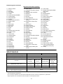
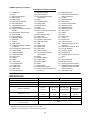
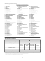
SPECIFICATIONS
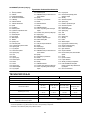
Model DUM166 DUM168
Effective cutting width 160 mm
Stroke per minute (min
-1
) 1,250
Rated voltage D.C. 14.4 V D.C. 18 V
Battery cartridge
BL1415 /
BL1415N
BL1430 / BL1440 /
BL1450
BL1815 / BL1815N /
BL1820 / BL1820B
BL1830 / BL1840 /
BL1840B / BL1850 /
BL1850B
Dimensions (L x W x H)
335 mm x 176 mm
x 130 mm
350 mm x 176 mm
x 130 mm
337 mm x 176 mm
x 130 mm
353 mm x 176 mm
x 130 mm
Net weight 1.3 kg 1.5 kg 1.4 kg 1.6 kg
Battery charger DC18RC, DC18SD
(Optional accessory)
Blade length of optional hedge shear blades
200 mm
• Due to our continuing program of research and development, the specifications herein are subject to change without notice.
• Specifications and battery cartridge may differ from country to country.
• Weight, with battery cartridge, according to EPTA-Procedure 01/2003

8
END010-4
Symbols
The following show the symbols used for the equipment.
Be sure that you understand their meaning before use.
・ Take particular care and attention.
・ Read instruction manual.
・ Danger; be aware of thrown objects.
・ Keep bystanders away.
・ Cutting means continues to run after the
motor is switched off.
・ Do not expose to moisture.
・ Only for EU countries
Do not dispose of electric equipment or
battery pack together with household
waste material!
In observance of the European
Directives, on Waste Electric and
Electronic Equipment and Batteries and
Accumulators and Waste Batteries and
Accumulators and their implementation
in accordance with national laws, electric
equipment and batteries and battery
pack(s) that have reached the end of
their life must be collected separately
and returned to an environmentally
compatible recycling facility.
ENE015-1
Intended use
The tool is intended for cutting lawn edges or sprouts.
ENG905-1
Noise
The typical A-weighted noise level determined according
to IEC60335:
Model DUM166
Sound pressure level (L
pA
) : 77 dB (A)
Uncertainty (K) : 2.5 dB (A)
The noise level under working may exceed 80 dB (A).
Model DUM168
Sound pressure level (L
pA
) : 78 dB (A)
Uncertainty (K) : 2.5 dB (A)
The noise level under working may exceed 80 dB (A).
Wear ear protection
ENG900-1
Vibration
The vibration total value (tri-axial vector sum)
determined according to IEC60335:
Vibration emission (a
h
) : 2.5 m/s
2
or less
Uncertainty (K) : 1.5 m/s
2
ENG901-1
•
The declared vibration emission value has been
measured in accordance with the standard test
method and may be used for comparing one tool
with another.
• The declared vibration emission value may also be
used in a preliminary assessment of exposure.
WARNING:
•
The vibration emission during actual use of the power
tool can differ from the declared emission value
depending on the ways in which the tool is used.
• Be sure to identify safety measures to protect the
operator that are based on an estimation of
exposure in the actual conditions of use (taking
account of all parts of the operating cycle such as
the times when the tool is switched off and when it
is running idle in addition to the trigger time).
Hedge trimming operation with optional hedge shear
blades
ENG905-1
Noise
The typical A-weighted noise level determined according
to EN60745:
Sound pressure level (L
pA
) : 74 dB (A)
Uncertainty (K) : 2.5 dB (A)
The noise level under working may exceed 80 dB (A).
Wear ear protection
ENG900-1
Vibration
The vibration total value (tri-axial vector sum)
determined according to EN60745:
Vibration emission (a
h
) : 2.5 m/s
2
or less
Uncertainty (K) : 1.5 m/s
2
ENG901-1
•
The declared vibration emission value has been
measured in accordance with the standard test
method and may be used for comparing one tool
with another.
• The declared vibration emission value may also be
used in a preliminary assessment of exposure.
WARNING:
• The vibration emission during actual use of the
power tool can differ from the declared emission
value depending on the ways in which the tool is
used.
• Be sure to identify safety measures to protect the
operator that are based on an estimation of
exposure in the actual conditions of use (taking
account of all parts of the operating cycle such as
the times when the tool is switched off and when it
is running idle in addition to the trigger time).
Cd
Ni-MH
Li-ion

9
ENH003-15
For European countries only
EC Declaration of Conformity
Makita declares that the following Machine(s):
Designation of Machine:
Cordless Grass Shear
Model No./ Type: DUM166,DUM168
Conforms to the following European Directives:
2006/42/EC
They are manufactured in accordance with the following
standard or standardized documents:
EN60745, EN60335
The technical file in accordance with 2006/42/EC is
available from:
Makita, Jan-Baptist Vinkstraat 2, 3070, Belgium
28.4.2015
000331
Yasushi Fukaya
Director
Makita, Jan-Baptist Vinkstraat 2, 3070, Belgium
ENH021-8
For European countries only
EC Declaration of Conformity
Makita declares that the following Machine(s):
Designation of Machine:
Cordless Hedge Trimmer
Model No./ Type: DUM166,DUM168
Specifications: see "SPECIFICATIONS" table.
Conforms to the following European Directives:
2000/14/EC, 2006/42/EC
They are manufactured in accordance with the following
standard or standardized documents:
EN60745
The technical file in accordance with 2006/42/EC is
available from:
Makita, Jan-Baptist Vinkstraat 2, 3070, Belgium
The conformity assessment procedure required by
Directive 2000/14/EC was in Accordance with annex V.
Measured Sound Power Level: 82 dB (A)
Guaranteed Sound Power Level: 84 dB (A)
28.4.2015
000331
Yasushi Fukaya
Director
Makita, Jan-Baptist Vinkstraat 2, 3070, Belgium
GEB070-2
CORDLESS GRASS SHEAR
SAFETY WARNINGS
WARNING! IMPORTANT READ CAREFULLY all
safety warnings and all instructions BEFORE USE.
Failure to follow the warnings and instructions may result
in electric shock, fire and/or serious injury.
Save all warnings and
instructions for future reference.
General instructions
1. To ensure correct operation, user has to read this
instruction manual to make himself familiar with
the handling of the equipment. Users insufficiently
informed will risk danger to themselves as well as
others due to improper handling.
2. Never allow people unfamiliar with these
instructions, people (including children) with
reduced physical, sensory or mental capabilities,
or lack of experience and knowledge to use the
equipment. Local regulations can restrict the age
of the operator.
3. Use the equipment with the utmost care and
attention.
4. Operate the equipment only if you are in good
physical condition. Perform all work calmly and
carefully. Use common sense and keep in mind
that the operator or user is responsible for
accidents or hazards occurring to other people or
their property.
5. Never operate the machine while people,
especially children, or pets are nearby.
6. Never use the equipment after consumption of
alcohol or drugs, or if feeling tired or ill.
7. The motor is to be switched off immediately in
case that the equipment shows any problem or
abnormal sign.
8.
Switch off and remove the battery cartridge when
resting and when leaving the equipment unattended,
and place it in a safe location to prevent danger to
others or damage to the equipment.
9. Don't force the equipment. It will do the job better
and with less likelihood of a risk of injury at the
rate for which it was designed.
10. Don't overreach. Keep proper footing and balance
at all times.
Personal protective equipment
1. Dress Properly. The clothing worn should be
functional and appropriate, i.e. it should be
tight-fitting but not cause hindrance. Do not wear
either jewelry or clothing which could become
entangled. Wear protective hair covering to
contain long hair.
2. Wear eye protection and stout shoes at all times
while operating the machine.

10
Electrical and battery safety
1. Avoid dangerous environment. Don't use the
equipment in damp or wet locations or expose it to
rain. Water entering an equipment will increase
the risk of electric shock.
2. Recharge only with the charger specified by the
manufacturer. A charger that is suitable for one
type of battery pack may create a risk of fire when
used with another battery pack.
3. Use power tools only with specifically designated
battery packs. Use of any other battery packs may
create a risk of injury and fire.
4. When battery pack is not in use, keep it away from
other metal objects, like paper clips, coins, keys,
nails, screws or other small metal objects, that
can make a connection from one terminal to
another. Shorting the battery terminals together
may cause burns or a fire.
5. Under abusive conditions, liquid may be ejected
from the battery; avoid contact. If contact
accidentally occurs, flush with water. If liquid
contacts eyes, additionally seek medical help.
Liquid ejected from the battery may cause
irritation or burns.
6. Do not dispose of the battery(ies) in a fire. The cell
may explode. Check with local codes for possible
special disposal instructions.
7. Do not open or mutilate the battery(ies). Released
electrolyte is corrosive and may cause damage to
the eyes or skin. It may be toxic if swallowed.
Starting up the equipment
1. Make sure that there are no children or other
people nearby, also pay attention to any animals
in the working vicinity. Otherwise stop using the
equipment.
2. Before use always check that the equipment is
safe for operation. Check the security of the
cutting tool and the guard and the switch
trigger/lever for easy and proper action. Check for
clean and dry handles and test the function of the
start/stop.
3. Check damaged parts before further use of the
equipment. A guard or other part that is damaged
should be carefully checked to determine that it
will operate properly and perform its intended
function. Check for alignment of moving parts,
binding of moving parts, breakage of parts,
mounting, and any other condition that may affect
its operation. A guard or other part that is
damaged should be properly repaired or replaced
by our authorized service center unless indicated
elsewhere in this manual.
4. Switch on the motor only when the hands and feet
are away from the cutting tool.
5. Before starting make sure that the cutting tool has
no contact with any objects.
Method of operation
1. Only use the equipment in good light and visibility.
During the winter season beware of slippery or
wet areas, ice and snow (risk of slipping). Always
ensure a safe footing.
2. Take care against injury to feet and hands from
the cutting tool.
3. Never stand on a ladder and run the equipment.
4. Never climb up into trees to perform cutting
operation with the equipment.
5. Never work on unstable surfaces.
6. Remove sand, stones, nails etc. found within the
working range. Foreign particles may damage the
cutting tool and can cause dangerous kick-backs.
7. Should the cutting tool hit stones or other hard
objects, immediately switch off the motor and
inspect the cutting tool.
8. Inspect the cutting tool at short regular intervals
for damage (detection of hairline cracks by means
of tapping-noise test).
9. Before commencing cutting, the cutting tool must
have reached full working speed.
10. The cutting tool has to be equipped with the
appropriate guard. Never run the equipment with
damaged guards or without guards in place!
11.
All protective installations and guards supplied with
the equipment must be used during operation.
12. Always remove the battery cartridge from the
equipment:
− whenever leaving the equipment unattended;
− before clearing a blockage;
− before checking, cleaning or working on the
equipment;
− after striking a foreign object;
− whenever the equipment starts vibrating
abnormally.
13. Always ensure that the ventilation openings are
kept clear of debris.
Cutting Tools
1. Employ only the correct cutting tool for the job in
hand.
Maintenance instructions
1. The condition of the equipment, in particular of the
cutting tool of the protective devices must be
checked before commencing work.
2. Turn off the motor and remove the battery
cartridge before carrying out maintenance,
replacing cutting tools or cleaning the equipment
or cutting tool.
3. Check loose fasteners and damaged parts such
as cracks in the cutting attachment.
4. Follow instructions for lubricating and changing
accessories.
5. When not in use, store the equipment indoors in
dry and high or locked-up place - out of the reach
of children. Clean and maintain before storage.

11
6. Use only the manufacturer's recommended
replacement parts and accessories.
7. Inspect and maintain the equipment regularly,
especially before/after use. Have the equipment
repaired only by our authorized service center.
8.
Keep handles dry, clean and free from oil and grease.
KEEP FOR FUTURE REFERENCE
WARNING:
DO NOT let comfort or familiarity with product (gained
from repeated use) replace strict adherence to safety
rules for the subject product. MISUSE or failure to follow
the safety rules stated in this instruction manual may
cause serious personal injury.
GEA010-1
General Power Tool Safety
Warnings
WARNING Read all safety warnings and all
instructions. Failure to follow the warnings and
instructions may result in electric shock, fire and/or
serious injury.
Save all warnings and instructions for
future reference.
GEB062-5
CORDLESS HEDGE TRIMMER
SAFETY WARNINGS
1.
Keep all parts of the body away from the cutter
blade. Do not remove cut material or hold
material to be cut when blades are moving. Make
sure the switch is off when clearing jammed
material.
A moment of inattention while operating the
hedge trimmer may result in serious personal injury.
2. Carry the hedge trimmer by the handle with
the cutter blade stopped. When transporting
or storing the hedge trimmer always fit the
cutting device cover. Proper handling of the
hedge trimmer will reduce possible personal injury
from the cutter blades.
3. Hold the power tool by insulated gripping
surfaces only, because the cutter blade may
contact hidden wiring. Cutter blades contacting
a "live" wire may make exposed metal parts of the
power tool "live" and could give the operator an
electric shock.
4.
Do not use the hedge trimmer in the rain or in wet or very
damp conditions. The electric motor is not waterproof.
5.
First-time users should have an experienced hedge
trimmer user show them how to use the trimmer.
6. The hedge trimmer must not be used by children
or young persons under 18 years of age. Young
persons over 16 years of age may be exempted
from this restriction if they are undergoing training
under the supervision of an expert.
7. Use the hedge trimmer only if you are in good
physical condition. If you are tired, your attention
will be reduced. Be especially careful at the end of
a working day. Perform all work calmly and
carefully. The user is responsible for all damages
to third parties.
8. Never use the trimmer when under the influence
of alcohol, drugs or medication.
9. Work gloves of stout leather are part of the basic
equipment of the hedge trimmer and must always
be worn when working with it. Also wear sturdy
shoes with anti-skid soles.
10. Before starting work check to make sure that the
trimmer is in good and safe working order. Ensure
guards are fitted properly. The hedge trimmer
must not be used unless fully assembled.
11. Make sure you have a secure footing before
starting operation.
12. Hold the tool firmly when using the tool.
13. Do not operate the tool at no-load unnecessarily.
14. Immediately switch off the motor and remove the
battery cartridge if the cutter should come into
contact with a fence or other hard object. Check
the cutter for damage, and if damaged repair
immediately.
15. Before checking the cutter, taking care of faults, or
removing material caught in the cutter, always
switch off the trimmer and remove the battery
cartridge.
16. Switch off the trimmer and remove the battery
cartridge before doing any maintenance work.
17. When moving the hedge trimmer to another
location, including during work, always remove
the battery cartridge and put the blade cover on
the cutter blades. Never carry or transport the
trimmer with the cutter running. Never grasp the
cutter with your hands.
18. Clean the hedge trimmer and especially the cutter
after use, and before putting the trimmer into
storage for extended periods. Lightly oil the cutter
and put on the cover. The cover supplied with the
unit can be hung on the wall, providing a safe and
practical way to store the hedge trimmer.
19. Store the hedge trimmer with the cover on, in a
dry room. Keep it out of reach of children. Never
store the trimmer outdoors.
SAVE THESE INSTRUCTIONS.
WARNING:
DO NOT let comfort or familiarity with product
(gained from repeated use) replace strict adherence
to safety rules for the subject product. MISUSE or
failure to follow the safety rules stated in this
instruction manual may cause serious personal
injury.

12
ENC007-9
IMPORTANT SAFETY
INSTRUCTIONS
FOR BATTERY CARTRIDGE
1. Before using battery cartridge, read all
instructions and cautionary markings on (1)
battery charger, (2) battery, and (3) product
using battery.
2. Do not disassemble battery cartridge.
3. If operating time has become excessively
shorter, stop operating immediately. It may
result in a risk of overheating, possible burns
and even an explosion.
4. If electrolyte gets into your eyes, rinse them
out with clear water and seek medical
attention right away. It may result in loss of
your eyesight.
5. Do not short the battery cartridge:
(1) Do not touch the terminals with any
conductive material.
(2) Avoid storing battery cartridge in a
container with other metal objects such as
nails, coins, etc.
(3) Do not expose battery cartridge to water
or rain.
A battery short can cause a large current flow,
overheating, possible burns and even a
breakdown.
6. Do not store the tool and battery cartridge in
locations where the temperature may reach or
exceed 50 ゚ C (122 ゚ F).
7. Do not incinerate the battery cartridge even if
it is severely damaged or is completely worn
out. The battery cartridge can explode in a fire.
8. Be careful not to drop or strike battery.
9. Do not use a damaged battery.
10. Follow your local regulations relating to
disposal of battery.
SAVE THESE INSTRUCTIONS.
Tips for maintaining maximum battery life
1. Charge the battery cartridge before
completely discharged.
Always stop tool operation and charge the
battery cartridge when you notice less tool
power.
2. Never recharge a fully charged battery
cartridge.
Overcharging shortens the battery service life.
3. Charge the battery cartridge with room
temperature at 10 ゚ C - 40 ゚ C (50 ゚ F - 104 ゚ F).
Let a hot battery cartridge cool down before
charging it.
4. Charge the battery cartridge if you do not use
it for a long period (more than six months).
FUNCTIONAL DESCRIPTION
CAUTION:
• Always be sure that the tool is switched off and the
battery cartridge is removed before adjusting or
checking function on the tool.
Installing or removing battery cartridge
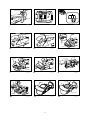
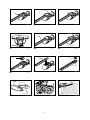
Fig.1
CAUTION:
• Always switch off the tool before installing or
removing of the battery cartridge.
•
Hold the tool and the battery cartridge firmly when
installing or removing battery cartridge.
Failure to
hold the tool and the battery cartridge firmly may cause
them to slip off your hands and result in damage to the
tool and battery cartridge and a personal injury.
To remove the battery cartridge, slide it from the tool
while sliding the button on the front of the cartridge.
To install the battery cartridge, align the tongue on the
battery cartridge with the groove in the housing and slip
it into place. Insert it all the way until it locks in place with
a little click. If you can see the red indicator on the upper
side of the button, it is not locked completely.
CAUTION:
• Always install the battery cartridge fully until the
red indicator cannot be seen. If not, it may
accidentally fall out of the tool, causing injury to
you or someone around you.
• Do not install the battery cartridge forcibly. If the
cartridge does not slide in easily, it is not being
inserted correctly.
Battery protection system
(Lithium-ion battery with star marking)
Fig.2
Lithium-ion batteries with a star marking are equipped
with a protection system. This system automatically cuts
off power to the tool to extend battery life.
The tool will automatically stop during operation if the
tool and/or battery are placed under one of the following
conditions:
• Overloaded:
The tool is operated in a manner that causes
it to draw an abnormally high current.
In this situation, release the trigger switch on
the tool and stop the application that caused
the tool to become overloaded. Then pull the
trigger switch again to restart.
If the tool does not start, the battery is
overheated. In this situation, let the battery
cool before pulling the trigger switch again.
• Low battery voltage:
The remaining battery capacity is too low and
the tool will not operate. In this situation,
remove and recharge the battery.

13
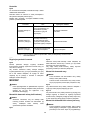
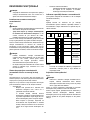
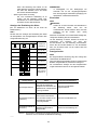
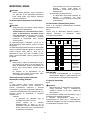
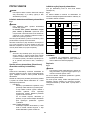
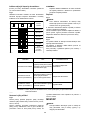
Indicating the remaining battery capacity
(Only for battery cartridges with "B" at the end of the
model number.)
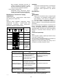
Fig.3
Press the check button on the battery cartridge to
indicate the remaining battery capacity. The indicator
lamps light up for few seconds.
Off
BlinkingLighted
Indicator lamps
Charge the
battery.
0% to 25%
25% to 50%
50% to 75%
75% to 100%
Remaining
capacity
The battery
may have
malfunctioned.
015658
NOTE:
• Depending on the conditions of use and the
ambient temperature, the indication may differ
slightly from the actual capacity.
Switch action
Fig.4
CAUTION:
• Before inserting the battery cartridge into the tool,
always check to see that the switch trigger
actuates properly and returns to the "OFF" position
when released.
To prevent the switch trigger from being accidentally
pulled, a lock-off button is provided.
To start the tool, depress the lock-off button and pull the
switch trigger. Release the switch trigger to stop. The
lock-off button can be pressed from either right or left side.
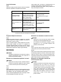
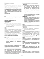
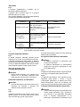
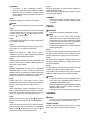
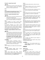
Indication lamp
Fig.5
Running the tool allows the indication lamp to show the
battery cartridge capacity status.
When the tool is also overloaded and has stopped
during operation, the lamp lights up in red.
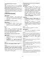
Refer to the following table for the status and action to
be taken for the indication lamp.
Note 1:
The time at which the indication lamp lights up varies by the temperature
around the work area and the battery cartridge conditions.
Indication lamp
The lamp blinks in red.
The lamp lights up in red.
(Note 1)
The lamp lights up in red.
(Note 1)
Status
This indicates the appropriate
time to replace the battery
cartridge when the battery
power becomes low.
This function works when the
battery power is almost used
up. At this time, tool stops
immediately.
Autostop due to overload.
Action to be taken
Recharge the battery cartridge
as soon as possible.
Recharge the battery cartridge.
Turn off the tool.
010970
Adjusting the shearing height
Fig.6
Changing the position of holding the change lever allows
three-stepped setting for sheared grass height (10 mm,
20 mm, 30 mm).
To change setting, tilt the change lever for the base frame
position and with the change lever tilted move it up or
down along the tool surface until the protrusion on base
frame fits in one of the holes in the tool and release it.
ASSEMBLY
CAUTION:
• Always be sure that the tool is switched off and the
battery cartridge is removed before carrying out
any work on the tool.

14
Installing or removing blade cover
CAUTION:
• Be careful not to contact the shear blade when
installing or removing the blade cover. Contacting
the shear blade may cause personal injuries.
Fig.7
Fig.8
Slide the blade cover from the tool's side until the shear
blade completely hides itself and then push in it lightly
towards the tool from the front.
To remove the blade cover, take the above installation
procedure in reverse.
Installing or removing base frame
CAUTION:
• Before installing or removing base frame, be sure
to install the blade cover.
• When installing or removing base frame, take care
that your fingers are not be pinched between the
tool and base frame.
Fig.9
To remove the base frame, upset the tool and take it out
of the groove grabbing its bottom.
Fig.10
To install the base frame, fit the protrusion of base frame
near the change lever into the hole for the sheared grass
height setting. With the base frame so fitted, pull the
lower part of base frame and fit the other part of the base
frame in the groove in the tool.
Installing or removing grass shear blades
CAUTION:
• Always be sure that the tool is switched off and the
battery cartridge is removed before installing or
removing shear blades. Failure to switch off and
remove the battery cartridge from the tool may
result in serious injury from accidental start-up.
• When replacing the shear blade, always wear
gloves without removing blade cover so that hands
and face does not directly contact the blade.
Failure to do so may cause personal injury.
NOTE:
• Do not wipe off grease from the gear and crank.
Failure to do so may cause damage to the tool.
• For specific way of removing and installing shear
blades refer to the reverse of a package for
accessory shear blades.
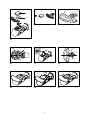
Fig.11
Remove the base frame and place the tool upside down.
CAUTION:
• Before placing the tool upside down, be sure to
remove the base frame.
Fig.12
To remove the shear blade, press the locking lever and
with the locking lever pressed turn the undercover
counterclockwise until the symbol
on the undercover
is aligned with the symbol
on the locking lever.
Fig.13
Take out the undercover, shear blade and crank in order
from the tool.
Fig.14
To install the grass shear blade, prepare the crank,
undercover and new grass shear blade.
Fig.15
Take out the blade cover from the old shear blades and
fit it onto the new ones for easy handling during the
replacement of blades.
Fig.16
Adjust the three pin position so that these pins are lined
up at right angle in relation to the basic alignment line on
the tool housing.
Fig.17
Fit the crank with its recessed part facing upwards onto
the pins. At this time, apply a small amount of grease to
the periphery of the crank using grease that the shear
blades as optional accessory are provided with or that
remains inside gear housing.
Fig.18
Overlap the oval hole in the upper blade with that in the
lower one. Move the shear blades so that the hole in the
base plate of shear blades are positioned in the center of
these overlapped oval holes.
Fig.19
Turn the shear blades upside down and install it so that
the pins on the tool fit in the hole in the shear blades.
Make sure that the shear blades are set in place
securely as far as they reach the base plate.
Fig.20
Place the undercover so that the symbol on the undercover
is aligned with the symbol
on the locking lever.
Fig.21
Press the undercover down and turn the undercover
clockwise while pressing it down until the symbol
on
the label is aligned with the symbol
on the locking
lever (the undercover is completely locked.).
Fig.22
At this time, make sure that the locking lever fits in the
groove in the undercover.
Remove the blade cover and then turn on the tool to
check it for proper movement.
NOTE:
• When the shear blades do not operate properly,
there is a poor fit between the blades and crank.
Redo from the beginning.

15
OPERATION
WARNING:
• Keep hands away from blades.
CAUTION:
• Smear the blade before and once per hour during
operation using machine oil or the like.
• Avoid operating the tool under the scorching
sunlight as much as practicable. When operating
the tool, be careful of your physical conditions.
• Hold the tool with one hand. Do not hold the front
bulge of the tool as a grip.
Fig.23
Turn the tool on after adjusting the shearing height and
hold it so that the foot of the tool rest on the ground.
Then gently move the tool forward into the area to be
cut.
Fig.24
When trimming around curb, fence or trees, move the
tool along them. Be careful for the blade not to contact
them.
Fig.25
When trimming sprouts or foliage of a small tree, remove
the base frame from the tool and cut little by little.
Shear big branches to your desired height beforehand
using branch scissors before using this tool.
CAUTION:
• When trimming twigs and foliage, do not attempt to
trim too much at a time. Proceed gently. Also do
not attempt to cut thick branches.
• Do not let the shear blades contact the grounds
during operation. The blades will be dulled,
causing poor performance.
• Do not trim wet grass or foliage of small trees.
MAINTENANCE
CAUTION:
• Always be sure that the tool is switched off and the
battery cartridge is removed before attempting to
perform inspection or maintenance.
Cleaning the tool
Clean out the tool by wiping off dust with a dry or
soap-dipped rag.
CAUTION:
• Never use gasoline, benzine, thinner, alcohol or
the like. Discoloration, deformation or cracks may
result.
Shear blade maintenance
Fig.26
Fig.27
After operation, remove dust from both sides of the
blade with wired brush, wipe it off with a rag and then
apply enough low-viscosity oil, such as machine oil etc.
and spray-type lubricating oil.
CAUTION:
• Do not wash the blades in water. Failure to do so
may cause rust or damage on the tool.
• Dirt and corrosion cause excessive blade friction
and shorten the operating time per battery charge.
After use
• To clean off the exterior of the tool, dampen a soft
cloth in a soapy water and wipe gently. Never use
thinner or benzine.
• Do not store the tool in a place where volatile
materials are stored.
To maintain product SAFETY and RELIABILITY, repairs,
any other maintenance or adjustment should be
performed by Makita Authorized Service Centers,
always using Makita replacement parts.
OPTIONAL ACCESSORIES
CAUTION:
• These accessories or attachments are
recommended for use with your Makita tool
specified in this manual. The use of any other
accessories or attachments might present a risk of
injury to persons. Only use accessory or
attachment for its stated purpose.
If you need any assistance for more details regarding
these accessories, ask your local Makita Service Center.
• Grass shear blade assembly
• Grass shear blade cover
• Base frame
• Makita genuine battery and charger
• Long handle attachment
For cordless hedge trimmer use
This tool can be used as a hedge trimmer by using the
hedge shear blade (optional accessory) and 2-way
change set (optional accessory).
To use this tool as a hedge trimmer, replacing the grass
shear blades with the hedge shear blades is required.
For removing the grass shear blades, refer to the
aforementioned section titled "Installing or removing
grass shear blades". For installing the hedge shear
blades, refer to the section below titled "Installing or
removing hedge shear blades".
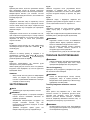
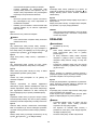
• Hedge shear blade assembly (for Hedge Trimmer)
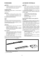
• 2-way change set consisting of the following two
accessories
• Hedge shear blade cover (for Hedge Trimmer)
• Storage case (for blade bottom section)

16
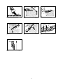
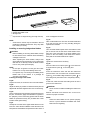
1
2
3
011044
•
Chip receiver for hedge trimming (for Hedge Trimmer)
NOTE:
• Some items in the list may be included in the tool
package as standard accessories. They may differ
from country to country.
Installing or removing hedge shear blades
CAUTION:
• Before installing or removing shear blades, always
be sure that the tool is switched off and the battery
cartridge is removed.
• When replacing the shear blades, always wear
gloves without removing blade cover so that hands
and face do not directly contact the blade. Failure
to do so may cause personal injury.
NOTE:
• Do not wipe off grease from the gear and crank.
Failure to do so may cause damage to the tool.
• For specific way of removing and installing shear
blades refer to the reverse of a package for
accessory shear blades.
Installing the hedge shear blades
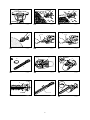
Fig.28
Prepare the crank, the undercover and new shear blades.
Fig.29
Adjust the three pin position so that these three pins are
aligned with the basic alignment line on the tool housing.
Fig.30
Fit the crank with its recessed part facing downward onto
the pins. At this time, apply a small amount of grease to
the periphery of the crank using grease that the shear
blades as optional accessory are provided with or that
remains inside gear housing.
Fig.31
Overlap the oval hole in the upper blade with that in the
lower one. Move the shear blades so that the hole in the
base plate of shear blades are positioned in the center of
these overlapped oval holes.
Fig.32
Take out the blade cover from the old shear blades and
fit it onto the new ones for easy handling during the
replacement of blades.
Fig.33
Turn the shear blades upside down and install it so that
pin on the tool fit in the hole in the shear blades. Fit the
bent part of the base plate of the shear blades to the
groove in the tool housing. Then make sure that the
base plate of the shear blades is set in place.
Fig.34
Tighten two screws with a coin firmly.
Fig.35
Place the undercover so that the symbol on the undercover
is aligned with the symbol
on the locking lever.
Fig.36
Press the undercover down and with the undercover
pressed down turn the undercover clockwise until the
symbol
on the label is aligned with the symbol on
the locking lever (the undercover is completely locked.).
Fig.37
At this time, make sure that the locking lever fits in the
groove in the undercover.
CAUTION:
• Never use the tool without installing the undercover
on it.
Remove the blade cover and then turn on the tool to
check it for proper movement.
NOTE:
• When the shear blades do not operate properly,
there is a poor fit between the blades and crank.
Redo from the beginning.
1. Hedge shear blade
2. Hedge shear blade cover
3. Storage case

17
Removing the hedge shear blades
Fig.38
CAUTION:
• Install the blade cover before removing or installing
the shear blades.
Reverse the tool.
Fig.39
To remove the shear blades, press the locking lever and
with the locking lever pressed turn the undercover
counterclockwise until the symbol
on the undercover
is aligned with the symbol
on the locking lever.
Fig.40
Take out the undercover from the tool.
Fig.41
Loosen two screws with a coin and remove the shear blades.
NOTE:
• Do not remove the screws. Without removing the
screws loosened, shear blades can be removed.
Fig.42
Remove the crank from the shear blades.
NOTE:
• The crank may remain in the tool.
Fig.43
NOTE:
• In the 2-way usage, the removed grass shear
blades need to be sheared in the blade storage
case and stored for future use.
OPERATION
Refer to the Important Safety Instructions before
operation.
CAUTION:
• Be careful not to accidentally contact a metal fence
or other hard objects while trimming. The blade will
break and may cause serious injury.
• Also, be careful for the shear blade not to contact
the ground.
• Overreaching with a hedge trimmer, particularly
from a ladder, is extremely dangerous. Do not work
from anything wobbly or infirm.
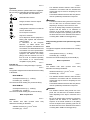
Fig.44
Do not attempt to cut branches thicker than 10 mm
diameter with this trimmer. These should first be cut with
shears down to the hedge trimming level.
CAUTION:
• Do not cut off dead trees or similar hard objects.
Failure to do so may damage the tool.
• Do not trim the grass or weeds while using hedge
shear blade. The shear blade may entangle the
grass or weeds.
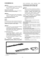
Fig.45
Hold the trimmer with one hand, depress the lock-off
button and pull the switch trigger and then move it in
front of your body.
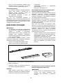
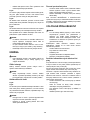
Fig.46
As a basic operation, tilt the blades towards the trimming
direction and move it calmly and slowly at the speed rate
of 3 - 4 seconds per meter.
Fig.47
To cut a hedge top evenly, it helps to tie a string at the
desired hedge height and to trim along it, using it as a
reference line.
Fig.48
Attaching the chip receiver (optional accessory) on the
tool when trimming the hedge straight can avoid cut off
leaves' being thrown away.
Fig.49
To cut a hedge side evenly, it helps to cut from the
bottom upwards.
Fig.50
Trim boxwood or rhododendron from the base toward
the top for a nice appearance and good job.
Installing or removing chip receiver
(optional accessory)
CAUTION:
• Always be sure that the tool is switched off and the
battery cartridge is removed before installing or
removing chip receiver.
NOTE:
•
When replacing the chip receiver, always wear gloves
so that hands and face does not directly contact the
blade. Failure to do so may cause personal injury.
• When replacing the chip receiver, always be
careful not to contact the shear blades.
• The chip receiver receives cut-off leaves and
alleviates collecting thrown-away leaves. This can
be installed on either side of the tool.
Fig.51
Place the chip receiver on the shear blades so that its
slits overlap with the screws on the shear blades and
secure it using two clamping nuts.
To remove the chip receiver, loosen and remove the two
clamping nuts and then take it out.
Storage
Fig.52
The hook hole in the tool bottom is convenient for
hanging the tool from a nail or screw on the wall.
Put the blade cover on the shear blades so that the
blades are not exposed. Store the tool out of the reach of
children carefully.
Store the tool in the place not exposed to water and rain.

18
УКРАЇНСЬКА (Оригінальні інструкції)
Пояснення до загального виду
1-1. Червоний індикатор
1-2. Кнопка
1-3. Касета з акумулятором
2-1. Маркувальна зірочка
3-1. Індикаторні лампи
3-2. Кнопка ПЕРЕВІРКА
4-1. Кнопка блокування вимкненого
положення
4-2. Кнопка вимикача
5-1. Лампочка індикатора
6-1. Важіль перемикання
6-2. Виступ на опорній рамі
6-3. Опорна рама
7-1. Лезо ножиців
7-2. Кришка диску
7-3. Рама полотна
9-1. Паз
9-2. Опорна рама
10-1. Важіль перемикання
10-2. Виступ на
опорній рамі
10-3. Опорна рама
11-1. Кришка диску
12-1. Важіль блокування
12-2. Захисна кришка
12-3. Натиснути
12-4. Поверніть
13-1. Захисна кришка
13-2. Ножове полотно
13-3. Кривошипний механізм
14-1. Кривошипний механізм
14-2. Захисна кришка
14-3. Лезо ножиців
15-1. Кришка диску
15-2. Лезо ножиців
16-1. Основна лінія вирівнювання на
корпусі інструмента
16-2. Шпильки
17-1. Прихована частина важеля
17-2. Кривошипний механізм
17-3. Використовуйте
мастило
17-4. Шпильки
18-1. Опорна плита
18-2.
Отвір в опорній пластині леза ножиців
18-3.
Овальні отвори, які перекриваються
20-1. Захисна кришка
20-2. Важіль блокування
22-1. Паз в захисній кришці
22-2. Важіль блокування
26-1. Щітка
27-1. Мастило
28-1. Кривошипний механізм
28-2. Захисна кришка
28-3. Лезо ножиців
29-1. Основна лінія вирівнювання на
корпусі інструмента
29-2. Шпильки
30-1. Прихована частина важеля
30-2. Кривошипний механізм
30-3. Використовуйте мастило
30-4. Шпильки
31-1. Опорна плита
31-2.
Овальні отвори, які перекриваються
31-3.
Отвір в опорній пластині леза ножиців
32-1. Кришка диску
33-1. Вигнута частина опорної
пластини леза ножиців
34-1. Гвинти
35-1. Важіль блокування
35-2. Захисна кришка
37-1. Паз в захисній кришці
37-2. Важіль блокування
38-1. Кришка диску
39-1. Важіль блокування
39-2. Захисна кришка
39-3. Натиснути
39-4. Поверніть
40-1. Захисна кришка
41-1. Гвинти
42-1. Кривошипний механізм
42-2. Лезо ножиців
43-1. Кришка леза ножиців для
підрізання трави
43-2.
Лезо ножиців для підрізання трави
43-3. Ящик для зберігання
46-1. Напрямок підрізування
46-2. Нахиліть полотно
46-3. Поверхня живоплоту, яку
необхідно підрізати
47-1. Шнурок
51-1. Затискні гайки
51-2. Уловлювач скалок
51-3. Шурупи на лезі ножиців
51-4. Перед встановленням
уловлювача скалок завжди
встановлюйте кришку
52-1. Отвір гачка
ТЕХНІЧНІ ХАРАКТЕРИСТИКИ
Модель DUM166 DUM168
Ефективна ширина підрізання 160 мм
Швидкість ножового полотна за хвилину (хв
-1
) 1250
Номінальна напруга 14,4 В пост. Тока 18 В пост. Тока
Касета з акумулятором
BL1415 /
BL1415N
BL1430 / BL1440 /
BL1450
BL1815 / BL1815N /
BL1820 / BL1820B
BL1830 / BL1840 /
BL1840B / BL1850 /
BL1850B
Розміри (Д х Ш х В)
335 мм x 176 мм
x 130 мм
350 мм x 176 мм
x 130 мм
337 мм x 176 мм
x 130 мм
353 мм x 176 мм
x 130 мм
Чиста вага 1,3 кг 1,5 кг 1,4 кг 1,6 кг
Зарядний пристрій DC18RC, DC18SD
(додаткове приладдя) Довжина додаткового
ножового полотна для підрізання живоплоту
200 мм
•
Через те, що ми не припиняємо програми досліджень і розвитку, наведені тут технічні характеристики можуть бути змінені без
• Технічні характеристики приладу та касета з акумулятором можуть відрізнятися в різних країнах.
• Вага разом з касетою з акумулятором відповідно до EPTA-Procedure 01/2003

19
END010-4
Символи
Далі наведені символи, які застосовуються для
позначення обладнання. Перед користуванням
переконайтеся, що Ви розумієте їхнє значення.
・ Будьте особливо уважні та обережні!
・ Читайте інструкцію з експлуатації.
・ Небезпека; пам’ятайте, що предмети
можуть відскочити.
・ Не підпускайте інших осіб.
・ Ріжуча частина продовжує рухатися
після того, як двигун було вимкнено
.
・ Не піддавайте інструмент впливу
вологи.
・ Тільки для країн ЄС
Не викидайте електроприлади або
акумуляторні батареї разом із
побутовим сміттям!
Згідно з Європейськими директивами
про утилізацію електричного та
електронного обладнання та про
утилізацію батарей та акумуляторів і
батарей та акумуляторів, термін
служби яких закінчився, та їх
використанням із дотриманням
національних законів, електричне
обладнання, батареї та акумулятори,
термін служби яких закінчився,
потрібно збирати окремо та
відправляти на екологічно чисті
підприємства з їхньої переробки.
ENE015-1
Цільове використання
Інструмент призначено для обрізання країв газонів та
порослі.
ENG905-1
Шум
Рівень шуму за шкалою А у типовому виконанні,
визначений відповідно до IEC60335:
Модель DUM166
Рівень звукового тиску (L
pA
): 77 дБ (A)
Похибка (K): 2,5 дБ (A)
Рівень шуму під час роботи може перевищувати
80 дБ (A).
Модель DUM168
Рівень звукового тиску (L
pA
): 78 дБ (A)
Похибка (K): 2,5 дБ (A)
Рівень шуму під час роботи може перевищувати
80 дБ (A).
Користуйтеся засобами захисту слуху
ENG900-1
Вібрація
Загальна величина вібрації (сума трьох векторів)
визначена згідно з IEC60335:
Вібрація (a
h
) : 2,5 м/с
2
або менше
Похибка (K): 1,5 м/с
2
ENG901-1
•
Заявлене значення вібрації було виміряно у
відповідності до стандартних методів
тестування та може використовуватися для
порівняння одного інструмента з іншим.
• Заявлене значення вібрації може також
використовуватися для попередньої оцінки
впливу.
УВАГА:
• Залежно від умов використання вібрація під час
фактичної роботи інструмента може
відрізнятися від заявленого значення вібрації.
• Забезпечте належні запобіжні заходи для
захисту оператора, що відповідатимуть умовам
використання інструмента (слід брати до уваги
всі складові робочого циклу, такі як час, коли
інструмент вимкнено та коли він починає
працювати на холостому ході під час запуску).
Підрізання живоплоту за допомогою додаткового
ножового полотна для підрізання живоплоту
ENG905-1
Шум
Рівень шуму за шкалою А у типовому виконанні,
визначений відповідно до EN60745:
Рівень звукового тиску (L
pA
): 74 дБ (A)
Похибка (K): 2,5 дБ (A)
Рівень шуму під час роботи може перевищувати
80 дБ (A).
Користуйтеся засобами захисту слуху
ENG900-1
Вібрація
Загальна величина вібрації (сума трьох векторів)
визначена згідно з EN60745:
Вібрація (a
h
) : 2,5 м/с
2
або менше
Похибка (K): 1,5 м/с
2
ENG901-1
•
Заявлене значення вібрації було виміряно у
відповідності до стандартних методів
тестування та може використовуватися для
порівняння одного інструмента з іншим.
•
Заявлене значення вібрації може також
використовуватися для попередньої оцінки впливу.
УВАГА:
• Залежно від умов використання вібрація під час
фактичної роботи інструмента може
відрізнятися від заявленого значення вібрації.
Cd
Ni-MH
Li-ion

20
• Забезпечте належні запобіжні заходи для
захисту оператора, що відповідатимуть умовам
використання інструмента (слід брати до уваги
всі складові робочого циклу, такі як час, коли
інструмент вимкнено та коли він починає
працювати на холостому ході під час запуску).
ENH003-15
Тільки для країн Європи
Декларація про відповідність стандартам ЄС
Компанія Makita наголошує на тому, що обладнання:
Позначення обладнання:
Акумуляторні ножиці для підрізання трави
№ моделі / тип: DUM166,DUM168
Відповідає таким Європейським Директивам:
2006/42/EC
Обладнання виготовлене відповідно до таких
стандартів або стандартизованих документів:
EN60745, EN60335
Технічну інформацію відповідно до 2006/42/EC
можна отримати:
Makita, Jan-Baptist Vinkstraat 2, 3070, Бельгія
28.4.2015
000331
Ясуші Фукайя
Директор
Makita, Jan-Baptist Vinkstraat 2, 3070, Бельгія
ENH021-8
Тільки для країн Європи
Декларація про відповідність стандартам ЄС
Компанія Makita наголошує на тому, що обладнання:
Позначення обладнання:
Акумуляторна пила для підрізання живоплоту
№ моделі / тип: DUM166,DUM168
Технічні характеристики: див. Таблицю
"ТЕХНІЧНІ ХАРАКТЕРИСТИКИ".
Відповідає таким Європейським Директивам:
2000/14/EC, 2006/42/EC
Обладнання виготовлене відповідно до таких
стандартів або стандартизованих документів:
EN60745
Технічну інформацію відповідно до 2006/42/EC
можна отримати:
Makita, Jan-Baptist Vinkstraat 2, 3070, Бельгія
Процедура оцінювання відповідності, якої вимагає
Директива 2000/14/EC, відбулася відповідно до
Додатка V.
Заміряний рівень
звукової потужності: 82 дБ (A)
Гарантований рівень звукової потужності: 84 дБ (A)
28.4.2015
000331
Ясуші Фукайя
Директор
Makita, Jan-Baptist Vinkstraat 2, 3070, Бельгія
GEB070-2
ПОПЕРЕДЖЕННЯ ПРО
НЕОБХІДНУ ОБЕРЕЖНІСТЬ ПІД
ЧАС РОБОТИ З
АКУМУЛЯТОРНИМИ НОЖИЦЯМИ
ДЛЯ ПІДРІЗАННЯ ТРАВИ
УВАГА! ВАЖЛИВО ПЕРЕД ВИКОРИСТАННЯМ
УВАЖНО прочитайте всі попередження про
необхідну обережність під час роботи та всі
інструкції. Недотримання попереджень та інструкцій
може призвести до ураження електричним струмом,
до виникнення пожежі та/або до отримання
серйозних травм.
Збережіть усі інструкції з
техніки безпеки та експлуатації
на майбутнє.
Загальні положення
1. Для того щоб забезпечити належну роботу,
користувач повинен прочитати цю інструкцію
для ознайомлення із правилами поводження з
пристроєм. Недостатньо інформовані
користувачі піддають себе та оточуючих людей
небезпеці через невірне поводження з
інструментом.
2. Ніколи не дозволяйте особам, які не
ознайомились з цією інструкцією, а також
людям (в тому числі дітям) з
обмеженими
фізичними, сенсорними або розумовими
здібностями та особам з недостатнім досвідом
і знаннями використовувати це обладнання.
Місцеві норми можуть обмежувати віковий
поріг оператора.
3. Пристроєм слід завжди користуватись із
максимальною обережністю та увагою.
4. Працювати із пристроєм можна тільки в
доброму фізичному стані. Усю роботу слід
виконувати спокійно та обережно. Керуйтеся
здоровим глуздом під час роботи та пам’ятайте,
що оператор або користувач несе
відповідальність за нещасні випадки та
небезпеку, яким піддаються інші люди або їхнє
майно.
Pagina se încarcă...
Pagina se încarcă...
Pagina se încarcă...
Pagina se încarcă...
Pagina se încarcă...
Pagina se încarcă...
Pagina se încarcă...
Pagina se încarcă...
Pagina se încarcă...
Pagina se încarcă...
Pagina se încarcă...
Pagina se încarcă...
Pagina se încarcă...
Pagina se încarcă...
Pagina se încarcă...
Pagina se încarcă...
Pagina se încarcă...
Pagina se încarcă...
Pagina se încarcă...
Pagina se încarcă...
Pagina se încarcă...
Pagina se încarcă...
Pagina se încarcă...
Pagina se încarcă...
Pagina se încarcă...
Pagina se încarcă...
Pagina se încarcă...
Pagina se încarcă...
Pagina se încarcă...
Pagina se încarcă...
Pagina se încarcă...
Pagina se încarcă...
Pagina se încarcă...
Pagina se încarcă...
Pagina se încarcă...
Pagina se încarcă...
Pagina se încarcă...
Pagina se încarcă...
Pagina se încarcă...
Pagina se încarcă...
Pagina se încarcă...
Pagina se încarcă...
Pagina se încarcă...
Pagina se încarcă...
Pagina se încarcă...
Pagina se încarcă...
Pagina se încarcă...
Pagina se încarcă...
Pagina se încarcă...
Pagina se încarcă...
Pagina se încarcă...
Pagina se încarcă...
Pagina se încarcă...
Pagina se încarcă...
Pagina se încarcă...
Pagina se încarcă...
Pagina se încarcă...
Pagina se încarcă...
Pagina se încarcă...
Pagina se încarcă...
Pagina se încarcă...
Pagina se încarcă...
Pagina se încarcă...
Pagina se încarcă...
Pagina se încarcă...
Pagina se încarcă...
Pagina se încarcă...
Pagina se încarcă...
Pagina se încarcă...
Pagina se încarcă...
Pagina se încarcă...
Pagina se încarcă...
Pagina se încarcă...
Pagina se încarcă...
Pagina se încarcă...
Pagina se încarcă...
Pagina se încarcă...
Pagina se încarcă...
Pagina se încarcă...
Pagina se încarcă...
Pagina se încarcă...
Pagina se încarcă...
Pagina se încarcă...
Pagina se încarcă...
-
 1
1
-
 2
2
-
 3
3
-
 4
4
-
 5
5
-
 6
6
-
 7
7
-
 8
8
-
 9
9
-
 10
10
-
 11
11
-
 12
12
-
 13
13
-
 14
14
-
 15
15
-
 16
16
-
 17
17
-
 18
18
-
 19
19
-
 20
20
-
 21
21
-
 22
22
-
 23
23
-
 24
24
-
 25
25
-
 26
26
-
 27
27
-
 28
28
-
 29
29
-
 30
30
-
 31
31
-
 32
32
-
 33
33
-
 34
34
-
 35
35
-
 36
36
-
 37
37
-
 38
38
-
 39
39
-
 40
40
-
 41
41
-
 42
42
-
 43
43
-
 44
44
-
 45
45
-
 46
46
-
 47
47
-
 48
48
-
 49
49
-
 50
50
-
 51
51
-
 52
52
-
 53
53
-
 54
54
-
 55
55
-
 56
56
-
 57
57
-
 58
58
-
 59
59
-
 60
60
-
 61
61
-
 62
62
-
 63
63
-
 64
64
-
 65
65
-
 66
66
-
 67
67
-
 68
68
-
 69
69
-
 70
70
-
 71
71
-
 72
72
-
 73
73
-
 74
74
-
 75
75
-
 76
76
-
 77
77
-
 78
78
-
 79
79
-
 80
80
-
 81
81
-
 82
82
-
 83
83
-
 84
84
-
 85
85
-
 86
86
-
 87
87
-
 88
88
-
 89
89
-
 90
90
-
 91
91
-
 92
92
-
 93
93
-
 94
94
-
 95
95
-
 96
96
-
 97
97
-
 98
98
-
 99
99
-
 100
100
-
 101
101
-
 102
102
-
 103
103
-
 104
104


Makita DUM166 Manual de utilizare
- Categorie
- Aparate de tuns gard viu
- Tip
- Manual de utilizare
- Acest manual este potrivit și pentru
în alte limbi
- slovenčina: Makita DUM166 Používateľská príručka
- polski: Makita DUM166 Instrukcja obsługi
Lucrări înrudite
-
Makita DUH506 Manual de utilizare
-
Makita UH004G Manual de utilizare
-
Makita UN460WD Manual de utilizare
-
Makita EN402MP Manual de utilizare
-
-
Makita DUN461W Manual de utilizare
-
-
-
Makita UH013G Manual de utilizare
-
Alte documente
-
Husqvarna 120iTK4-H Professional Plus Induction Hob Manual de utilizare
-
McCulloch Li 40HT Manualul proprietarului
-
Ikra BDA GBS 8050 LI Manualul proprietarului
-
Worx WG259E.5 Fișa cu date
-
-
K RCHER GSH 2 Plus Manual de utilizare
-
Graphite 58GE119 Manualul proprietarului
-
Dolmar AT1831U Manualul proprietarului
-
-