ESAB GMH Manual de utilizare
- Categorie
- Sistem de sudare
- Tip
- Manual de utilizare

Valid for serial no. 845--xxx--xxxx0460 671 001 2008--11--03
GMH
Bruksanvisning
Brugsanvisning
Bruksanvisning
Käyttöohjeet
Instruction manual
Betriebsanweisung
Manuel d’instructions
Gebruiksaanwijzing
Instrucciones de uso
Istruzioni per l’uso
Manual de instruções
Ïäçãßåò ÷ñÞóåùò
Instrukcja obs³ugi
Kezelési utasítások
Návod k pou¾ívání
Navod na pouitie
Lieto¹anas pamàcïba
Eksploatavimo instrukcijos
Priruènik s uputama
Manualul de instrucþiuni

-- 2 --
Rätt till ändring av specifikationer utan avisering förbehålles.
Ret til ændring af specifikationer uden varsel forbeholdes.
Rett til å endre spesifikasjoner uten varsel forbeholdes.
Oikeudet muutoksiin pidätetään.
Rights reserved to alter specifications without notice.
Änderungen vorbehalten.
Sous réserve de modifications sans avis préalable.
Recht op wijzigingen zonder voorafgaande mededeling voorbehouden.
Reservado el derecho de cambiar las especificaciones sin previo aviso.
Ci riserviamo il diritto di variare le specifiche senza preavviso.
Reservamo--nos o direito de alterar as especificações sem aviso prévio.
Äéáôçñåßôáé ôï äéêáßùìá ôñïðïðïßçóçò ðñïäéáãñáöþí ×ùñßò ðñïåéäïðïßçóç.
Zastrzegamy sobie prawo do wprowadzenia zmian.
Fenntartjuk az elözetes bejelentés nélküli változtatás jogát.
Výrobce si vyhrazuje právo na zmìnu údajû bez pøedcházejiciho upozomìni.
Výrobca si v y hradzuje právo na uskutoènenie zmien bez upovedomenia.
Tiek paturºtas tiesïbas bez iepriek¹ºja brïdinàjuma izmainït specifikàcijas.
Įmonė pasilieka teisę keisti specifikacijas be įspėjimo.
Rights reserved to alter specifications without notice.
Rights reserved to alter specifications without notice.
SVENSKA 5..............................................
DANSK 25................................................
NORSK 45................................................
SUOMI 65................................................
ENGLISH 85..............................................
DEUTSCH 105.............................................
FRANÇAIS 125.............................................
NEDERLANDS 145.........................................
ESPAÑOL 165..............................................
ITALIANO 185..............................................
PORTUGUÊS 205..........................................
ÅËËÇÍÉÊÁ 225.............................................
POLSKI 245.................................................
MAGYAR 265................................................
ÈESKY 285.................................................
SLOVENSKY 305.............................................
LATVIE©U 325...............................................
LIETUVIÙK 345..........................................
HRVATSKI 365..............................................
Rumanian 385...............................................

3
Enheten är provad av ESAB i en allmän inkoppling.
Ansvaret för den slutliga inkopplingens säkerhet och funktion åligger Intergratören.
-- -- -- -- -- -- -- -- -- -- -- -- -- -- -- -- -- -- -- -- -- -- -- -- -- -- -- -- -- -- -- -- -- -- -- -- -- -- -- -- -- -- -- -- -- -- -- -- -- -- -- -- -- -- -- -- -- -- -- -- -- -- -- --------------------------------------
Enheden er testet af ESAB i en generel forbindelse.
Ansvaret for den endelige forbindelses sikkerhed og funktion påhviler integratoren.
-- -- -- -- -- -- -- -- -- -- -- -- -- -- -- -- -- -- -- -- -- -- -- -- -- -- -- -- -- -- -- -- -- -- -- -- -- -- -- -- -- -- -- -- -- -- -- -- -- -- -- -- -- -- -- -- -- -- -- -- -- -- -- --------------------------------------
Enheten er testet av ESAB i en generell tilkobling. Den som integrerer systemet, har ansvaret for sik-
kerheten og funksjonen ved den endelige tilkoblingen.
-- -- -- -- -- -- -- -- -- -- -- -- -- -- -- -- -- -- -- -- -- -- -- -- -- -- -- -- -- -- -- -- -- -- -- -- -- -- -- -- -- -- -- -- -- -- -- -- -- -- -- -- -- -- -- -- -- -- -- -- -- -- -- --------------------------------------
ESAB on koekäyttänyt yksikön yleisessä sähköliitännässä.
Vastuu lopullisen kytkennän turvallisuudesta ja toimimisesta on integraattorilla.
-- -- -- -- -- -- -- -- -- -- -- -- -- -- -- -- -- -- -- -- -- -- -- -- -- -- -- -- -- -- -- -- -- -- -- -- -- -- -- -- -- -- -- -- -- -- -- -- -- -- -- -- -- -- -- -- -- -- -- -- -- -- -- --------------------------------------
The unit is tested by ESAB in a general purpose operation.
Responsibility for the safety and function of the final operation remains with the Integrator.
-- -- -- -- -- -- -- -- -- -- -- -- -- -- -- -- -- -- -- -- -- -- -- -- -- -- -- -- -- -- -- -- -- -- -- -- -- -- -- -- -- -- -- -- -- -- -- -- -- -- -- -- -- -- -- -- -- -- -- -- -- -- -- --------------------------------------
Die Einheit wurde von ESAB in einer allgemeinen Schaltung geprüft.
Die Verantwortung für die Sicherheit und Funktion der letztendlichen Schaltung liegt beim Integrator.
-- -- -- -- -- -- -- -- -- -- -- -- -- -- -- -- -- -- -- -- -- -- -- -- -- -- -- -- -- -- -- -- -- -- -- -- -- -- -- -- -- -- -- -- -- -- -- -- -- -- -- -- -- -- -- -- -- -- -- -- -- -- -- --------------------------------------
L’unité est testée par ESAB sur un raccordement général.
L’Intégrateur est le seul responsable de la sécurité et du fonctionnement du raccordement définitif.
-- -- -- -- -- -- -- -- -- -- -- -- -- -- -- -- -- -- -- -- -- -- -- -- -- -- -- -- -- -- -- -- -- -- -- -- -- -- -- -- -- -- -- -- -- -- -- -- -- -- -- -- -- -- -- -- -- -- -- -- -- -- -- --------------------------------------
De eenheid werd door ESAB getest in een algemene schakeling.
Diegene die de uiteindelijke schakeling uitvoert is aansprakelijk voor de veiligheid en werking ervan.
-- -- -- -- -- -- -- -- -- -- -- -- -- -- -- -- -- -- -- -- -- -- -- -- -- -- -- -- -- -- -- -- -- -- -- -- -- -- -- -- -- -- -- -- -- -- -- -- -- -- -- -- -- -- -- -- -- -- -- -- -- -- -- --------------------------------------
La unidad ha sido probada por ESAB en una conexión general.
La seguridad y la funcionalidad de la conexión final son responsabilidad del Integrador.
-- -- -- -- -- -- -- -- -- -- -- -- -- -- -- -- -- -- -- -- -- -- -- -- -- -- -- -- -- -- -- -- -- -- -- -- -- -- -- -- -- -- -- -- -- -- -- -- -- -- -- -- -- -- -- -- -- -- -- -- -- -- -- --------------------------------------
L’unità è stata testata da ESAB in un impianto generico.
La sicurezza e il funzionamento dell’impianto finale sono di responsabilità dell’installatore.
-- -- -- -- -- -- -- -- -- -- -- -- -- -- -- -- -- -- -- -- -- -- -- -- -- -- -- -- -- -- -- -- -- -- -- -- -- -- -- -- -- -- -- -- -- -- -- -- -- -- -- -- -- -- -- -- -- -- -- -- -- -- -- --------------------------------------
A unidade foi testada pela ESAB numa ligação de carácter geral.
O integrador é responsável pela segurança da ligação final e pelo funcionamento.
-- -- -- -- -- -- -- -- -- -- -- -- -- -- -- -- -- -- -- -- -- -- -- -- -- -- -- -- -- -- -- -- -- -- -- -- -- -- -- -- -- -- -- -- -- -- -- -- -- -- -- -- -- -- -- -- -- -- -- -- -- -- -- --------------------------------------
Ç ìïíÜäá åßíáé äïêéìáóìÝíç áðü ôçí ESAB óå ìå êïéíÞ óýíäåóç.
Ç åõèýíç ãéá ôçí áóöÜëåéá êáé ëåéôïõñãßá ôçò ôåëéêÞò óýíäåóçò åßíáé ôïõ ïëïêëçñùôÞ.
-- -- -- -- -- -- -- -- -- -- -- -- -- -- -- -- -- -- -- -- -- -- -- -- -- -- -- -- -- -- -- -- -- -- -- -- -- -- -- -- -- -- -- -- -- -- -- -- -- -- -- -- -- -- -- -- -- -- -- -- -- -- -- --------------------------------------
Jednostka zosta³a przetestowana przez firmê ESAB dla ogólnej konfiguracji pod³±czenia.
Za bezpieczeñstwo i dzia³anie koñcowej konfiguracji pod³±czenia odpowiada Wykonawca.
-- -- -- -- -- -- -- -- -- -- -- -- -- -- -- -- -- -- -- -- -- -- -- -- -- -- -- -- -- -- -- -- -- -- -- -- -- -- -- -- -- -- -- -- -- -- -- -- -- -- -- -- -- -- -- -- -- -- -- -- -- -- -- --------------------------------------
Az egység az ESAB cégnél egy általános célú mûvelet során kipróbálásra került.
A végsõ mûködés során a biztonságért és a mûködésért az integrátor felel.
-- -- -- -- -- -- -- -- -- -- -- -- -- -- -- -- -- -- -- -- -- -- -- -- -- -- -- -- -- -- -- -- -- -- -- -- -- -- -- -- -- -- -- -- -- -- -- -- -- -- -- -- -- -- -- -- -- -- -- -- -- -- -- --------------------------------------
Spoleènost ESAB jednotku testuje v obecném provozu.
Odpovìdnost za bezpeènost a funkènost koneèného provozu nese osoba, která provedla zabudování.
-- -- -- -- -- -- -- -- -- -- -- -- -- -- -- -- -- -- -- -- -- -- -- -- -- -- -- -- -- -- -- -- -- -- -- -- -- -- -- -- -- -- -- -- -- -- -- -- -- -- -- -- -- -- -- -- -- -- -- -- -- -- -- --------------------------------------
Jednotka je testovaná vo všeobecnej prevádzke spoloènos»ou ESAB.
Za bezpeènos» a funkènos» koneènej prevádzky stále zodpovedá integrátor.
-- -- -- -- -- -- -- -- -- -- -- -- -- -- -- -- -- -- -- -- -- -- -- -- -- -- -- -- -- -- -- -- -- -- -- -- -- -- -- -- -- -- -- -- -- -- -- -- -- -- -- -- -- -- -- -- -- -- -- -- -- -- -- --------------------------------------
Iekàrta ir ESAB pàrbaudïta vispusïgas ekspluatàcijas apstàk¶os.
Par galaizmanto¹anas dro¹ïbu un darbïbu atbildïgs ir integrators.
-- -- -- -- -- -- -- -- -- -- -- -- -- -- -- -- -- -- -- -- -- -- -- -- -- -- -- -- -- -- -- -- -- -- -- -- -- -- -- -- -- -- -- -- -- -- -- -- -- -- -- -- -- -- -- -- -- -- -- -- -- -- -- --------------------------------------
Įrenginio veikimas naudojant jį pagal benrąj
ą paskirtį patikrintas ESAB.
Už įrenginio galutinio veikimo saugą ir funkcijas atsako įrangos montuotojas.
-- -- -- -- -- -- -- -- -- -- -- -- -- -- -- -- -- -- -- -- -- -- -- -- -- -- -- -- -- -- -- -- -- -- -- -- -- -- -- -- -- -- -- -- -- -- -- -- -- -- -- -- -- -- -- -- -- -- -- -- -- -- -- --------------------------------------
ESAB je testirao jedinicu u operaciji opæe namjene.
Odgovornost za sigurnost i funkciju završne operacije ostaje na Integrator u.

4
-- -- -- -- -- -- -- -- -- -- -- -- -- -- -- -- -- -- -- -- -- -- -- -- -- -- -- -- -- -- -- -- -- -- -- -- -- -- -- -- -- -- -- -- -- -- -- -- -- -- -- -- -- -- -- -- -- -- -- -- -- -- -- --------------------------------------
Unitatea este testatã de ESAB în timpul funcþionãrii în scop general.
Responsabilitatea pentru siguranþã ºi funcþionarea finalã este a Integratorului.
-- -- -- -- -- -- -- -- -- -- -- -- -- -- -- -- -- -- -- -- -- -- -- -- -- -- -- -- -- -- -- -- -- -- -- -- -- -- -- -- -- -- -- -- -- -- -- -- -- -- -- -- -- -- -- -- -- -- -- -- -- -- -- --------------------------------------

ENGLISH
-- 8 5 --
TOCe
1SAFETY 86...........................................................
2 INTRODUCTION 88...................................................
2.1 General 88..................................................................
2.2 Variants 88..................................................................
2.3 Technical data 89............................................................
2.4 Main parts 90................................................................
3 INSTALLATION 92....................................................
3.1 General 92..................................................................
3.2 Installation and connection 92..................................................
3.3 Tuning the sensor finger 92....................................................
3.4 Tuning the inductive sensor 92.................................................
4 OPERATION 93.......................................................
4.1 General 93..................................................................
4.2 Joint--tracking unit with control panel 93.........................................
4.3 Joint--tracking unit -- rear section 95.............................................
4.4 Portable control box 96.......................................................
4.5 Joint--tracking 98.............................................................
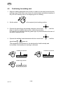
4.6 Positioning for welding start 101.................................................
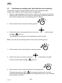
4.7 Positioning for welding start (with inductive joint--tracking) 102.......................
5 MAINTENANCE 103....................................................
5.1 General 103..................................................................
5.2 Wear parts 103...............................................................
6 ACCESSORIES 104....................................................
DIAGRAM 405............................................................
DIMENSION DRAWING 408................................................
SPARE PARTS LIST 411...................................................

-- 8 6 --
SafGB
1SAFETY
Users of ESAB welding equipment have the ultimate responsibility for ensuring that anyone who
works on or near the equipment observes all the relevant safety precautions. Safety precautions
must meet the requirements that apply to this type of welding equipment. The following recommen-
dations should be observed in addition to the standard regulations that apply to the workplace.
All work must be carried out by trained personnel well--acquainted with the operation of the welding
equipment. Incorrect operation of the equipment may lead to hazardous situations which can result
in injury to the operator and damage to the equipment.
1. Anyone who uses the welding equipment must be familiar with:
S its operation
S location of emergency stops
S its function
S relevant safety precautions
S welding
2. The operator must ensure that:
S no unauthorised person is stationed within the working area of the equipment when it is
started up.
S no--one is unprotected when the arc is struck
3. The workplace must:
S be suitable for the purpose
S be free from draughts
4. Personal safety equipment
S Always wear recommended personal safety equipment, such as safety glasses, flame--proof
clothing, safety gloves.
S Do not wear loose--fitting items, such as scarves, bracelets, rings, etc., which could become
trapped or cause burns.
5. General precautions
S Make sure the return cable is connected securely.
S Work on high voltage equipment may only be carried out by a qualified electrician.
S Appropriate fire extinquishing equipment must be clearly marked and close at hand.
S Lubrication and maintenance must not be carried out on the equipment during operation.
GB

-- 8 7 --
SafGB
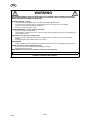
WARNING
READ AND UNDERSTAND THE INSTRUCTION MANUAL BEFORE INSTALLING OR OPERATING.
ARC WELDING AND CUTTING CAN BE INJURIOUS TO YOURSELF AND OTHERS. TAKE PRECAU -
TIONS WHEN WELDING. ASK FOR YOUR EMPLOYER’S SAFETY PRACTICES WHICH SHOULD BE
BASED ON MANUFACTURERS’ HAZARD DATA.
ELECTRIC SHOCK -- Can kill
S Install and earth the welding unit in accordance with applicable standards.
S Do not touch live electrical parts or electrodes with bare skin, wet gloves or wet clothing.
S Insulate yourself from earth and the workpiece.
S Ensure your working stance is safe.
FUMES AND GASES -- Can be dangerous to health
S Keep your head out of the fumes.
S Use ventilation, extraction at the arc, or both, to take fumes and gases away from your breathing zone
and the general area.
ARC RAYS -- Can injure eyes and burn skin.
S Protect your eyes and body. Use the correct welding screen and filter lens and wear protective
clothing.
S Protect bystanders with suitable screens or curtains.
FIRE HAZARD
S Sparks (spatter) can cause fire. Make sure therefore that there are no inflammable materials nearby.
NOISE -- Excessive noise can damage hearing
S Protect your ears. Use earmuffs or other hearing protection.
S Warn bystanders of the risk.
MALFUNCTION -- Call for expert assistance in the event of malfunction.
PROTECT YOURSELF AND OTHERS!
GB

-- 8 8 --
hga1d1ea
2 INTRODUCTION
2.1 General
GMH is joint--tracking equipment for the positioning and joint--tracking of automatic
welding equipment in all types of joint that arise where the sensor finger has a
guiding edge to follow. The equipment is adapted to ESAB’s standard servo slides
and control one or two servo motors simultaneously.
The system is available in several variants, see below.
2.2 Variants
S Joint--tracking unit with control panel.
S Joint--tracking unit with portable control box.
S Built--in component for columns and booms.
GB

-- 8 9 --
hga1d1ea
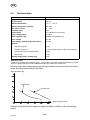
2.3 Technical data
GMH
Supply voltage 42V AC, 50--60 Hz
Current output 450 V A
Ambient temperature -- 1 5 ° C--+45° C
Relative atmospheric humidity Max. 98%
Max. motor current 6A 100%
Enclosure class IP 23
Current limits 15 A (hardware current limit)
Power supply fusing 10 A slow
Motor regulator, type Switched four quadrant reg.
Rotor voltage 40 V DC
Field voltage, separate magnetised motor 60 V DC
Weights:
Joint--tracking unit:
Portable control box:
Sensor and slide cross with bracket:
Guide finger:
6,2 kg
2,7 kg (complete with 4m cable and protection)
2.2 kg
0.6 kg
Working range sensor, radially 360° 4mm
Enclosure class
The IP code indicates the enclosure class, i. e. the degree of protection against penetration by solid
objects or water. Equipment marked IP 23 is designed for indoor and outdoor use.
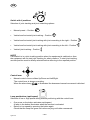
Working range and setting speed, see the figure below and the technical description
in the operating instructions for A6 Slide.
Normal ratio
Inverted ratio
Angle deviation deg
Welding speed cm/min
Diagram of the weld joint’s maximum angle deviation in relation to the set welding
speed.
GB

-- 9 0 --
hga1d1ea
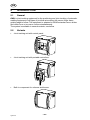
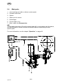
2.4 Main parts
1. Joint--tracking unit (with or without control panel)
2. Portable control box
3. Sensor
4. Slide cross for sensor
5. Guide finger
6. Control cable (2 m)
7. Motor cable (see Accessories)
NB!
The portable control box (2) and the control cable (6), in accordance with the above,
are discontinued for certain columns and booms and are replaced by product
specific parts.
For more information, see the chapter ”Operation”, on page 93.
GB

-- 9 1 --
hga1d1ea
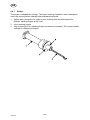
2.4.1 Sensor
The sensor is shaped like a finger. The finger is spring--loaded so that it attempts to
reach the centre position laterally and downwards vertically.
1. Sensor with connection for cable to joint--tracking unit and with bracket for
different tracking fingers at the front.
2. Joint--tracking fingers
3. Stop screws (two) for adjusting finger movement horizontally. The screws enable
settings for different joint types.
GB

-- 9 2 --
hga1i1ea
3 INSTALLATION
3.1 General
The installation must be executed by a professional.
3.2 Installation and connection
1. Measurement information, see the dimension drawings on pages 408--410.
2. Connection, see the diagrams on pages 405--407
3. Check that the required output and voltage is available for complete installation.
4. Fit the guide finger parallel with the motor driven slide cross.
3.3 Tuning the sensor finger
Please refer to ESAB’s service department for tuning the sensor finger.
3.4 Tuning the inductive sensor
Please refer to ESAB’s service department for tuning the inductive sensor.
GB

-- 9 3 --
hga1o1ea
4 OPERATION
4.1 General
General safety regulations for the handling of the equipment can be found on
page 86. Read through before you start using the equipment!
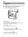
4.2 Joint--tracking unit with control panel
Emergency stop (1)
S One press on the button activates EMERGENCY STOP
NB! An emergency stop must never be reset before the cause of the abnormal
function or signal has been established and rectified.
Signal lamp
(white)
S Illuminates when the power has been switched on.
Alarm lamp (automatic joint-tracking)
(yellow)
S Illuminates when the guide finger is outside the working range (vertical).
The automatic function is then blocked.
Signal lamp (joint--tracking)
(green)
S Illuminates when automatic joint--tracking is in progress.
GB

-- 9 4 --
hga1o1ea
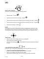
Switch with 5 positions
Selection of joint--tracking and joint--searching options:
S Manual preset -- Position
S Vertical and horizontal joint--tracking -- Position
S Vertical and horizontal joint--tracking with joint--searching to the right -- Position
S Vertical and horizontal joint--tracking with joint--searching to the left -- Position
S Vertical joint--tracking -- Position
NOTE!
If the switch is in a joint--tracking position when the equipment is switched on then
the equipment will not start joint--tracking for safety reasons. To start joint--tracking,
another position must be briefly selected before returning to the required position.
Control lever
S Manual control of servo slides Up/Down and Left/Right.
The control lever is always overriding.
When the alarm lamp
is illuminated the downward manual movement is
blocked.
Lamp pushbutton (rapid speed)
Selection of low or high speed during manual positioning with the control lever.
S One press on the button activates rapid speed.
A lamp in the button illuminates when the function is activated.
S Return to low speed by pressing the button again
Check that the lamp has gone out before carrying out further commands.
GB

-- 9 5 --
hga1o1ea
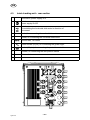
4.3 Joint--tracking unit -- rear section
1 Connection, power supply 42 V
2
Switch
Power supply On/Off
3
Switch
For switching the horizontal slide motor’s direction of
movement.
4 Socket, for connecting the vertical slide motor
5 Socket, for connecting the horizontal slide motor
6 Control fuse, 10 A slow
7 Sleeve socket (8--pin), for connecting the guide finger.
8 Socket (23--pin), for connecting the portable control box.
9 Sockets, for connecting the limit position switch
10 Extra sockets
11 Service contacts
GB

-- 9 6 --
hga1o1ea
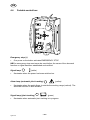
4.4 Portable control box
Emergency stop (1)
S One press on the button activates EMERGENCY STOP
NB! An emergency stop must never be reset before the cause of the abnormal
function or signal has been established and rectified.
Signal lamp (white)
S Illuminates when the power has been switched on.
Alarm lamp (automatic joint-tracking)
(yellow)
S Illuminates when the guide finger is outside the working range (vertical). The
automatic function is then blocked.
Signal lamp (joint--tracking)
(green)
S Illuminates when automatic joint--tracking is in progress.
GB

-- 9 7 --
hga1o1ea
Switch with 5 positions
Selection of joint--tracking and joint--searching options:
S Manual preset -- Position
S Vertical and horizontal joint--tracking -- Position
S Vertical and horizontal joint--tracking with joint--searching to the right -- Position
S Vertical and horizontal joint--tracking with joint--searching to the left -- Position
S Vertical joint--tracking -- Position
NOTE!
If the switch is in a joint--tracking position when the equipment is switched on then
the equipment will not start joint--tracking for safety reasons. To start joint--tracking,
another position must be briefly selected before returning to the required position.
Control lever
S Manual control of servo slides Up/Down and Left/Right.
The control lever is always overriding.
When the alarm lamp is illuminated the downward manual movement is blocked.
Lamp pushbutton (rapid speed)
Selection of low or high speed during manual positioning with the control lever.
S One press on the button activates rapid speed.
A lamp in the button illuminates when the function is activated.
S Return to low speed by pressing the button again
Check that the lamp has gone out before carrying out further commands.
GB

-- 9 8 --
hga1o1ea
4.5 Joint--tracking
The joint--tracking equipment can be set for different types of joint--tracking. It can be
set for joint--tracking with edge control and for joint--tracking with groove control. The
setting is made both on the control box and on the sensor.
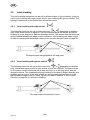
4.5.1 Joint--tracking with edge control
The following functions are set on the control box, or depending on whether
right of left--hand control is required. The two stop screws on the sensor should be
screwed in to the stop point. See the illustration below. This means that the fuses are
spring--loaded laterally and edge control is allowed. Joint--tracking with edge control
is used for welding fillet welds and similar joints, see also the joint table on page 99.
The stop screws are tightened to the stop point.
4.5.2 Joint--tracking with groove control
The following functions are set on the control box, or depending on whether
both vertical and lateral control or just vertical control are required. The stop screws
on the sensor must be screwed out at least two turns or to the stop point, see the
illustration below. This releases the spring loading for the search fingers laterally and
enables groove control. If the stop screws are not screwed out then there is a risk
that the search fingers start to ”climb” up the joint walls in shallow V and U--joints.
See also on page 99 for selection of setting.
The stop screws screwed out 2 turns
GB

-- 9 9 --
hga1o1ea
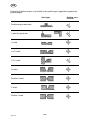
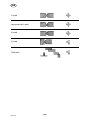
Examples of different types of joint and of the guide finger’s application against the
guiding edges.
Joint type Setting, con-
trol box
Double flanged butt weld
I--weld (A=guide bar)
V--weld
1/2 V--weld
1/2 V--weld
U--weld
Double U--weld
J--weld
Double J--weld
GB

-- 1 0 0 --
hga1o1ea
X--weld
Asymmetrical X--weld
K--weld
K--weld
Fillet weld
GB
Pagina se încarcă...
Pagina se încarcă...
Pagina se încarcă...
Pagina se încarcă...
Pagina se încarcă...
Pagina se încarcă...
-
 1
1
-
 2
2
-
 3
3
-
 4
4
-
 5
5
-
 6
6
-
 7
7
-
 8
8
-
 9
9
-
 10
10
-
 11
11
-
 12
12
-
 13
13
-
 14
14
-
 15
15
-
 16
16
-
 17
17
-
 18
18
-
 19
19
-
 20
20
-
 21
21
-
 22
22
-
 23
23
-
 24
24
-
 25
25
-
 26
26


ESAB GMH Manual de utilizare
- Categorie
- Sistem de sudare
- Tip
- Manual de utilizare
în alte limbi
- English: ESAB GMH User manual
Lucrări înrudite
-
ESAB PAV Manual de utilizare
-
-
-
-
-
ESAB EWT 1000 Manual de utilizare
-
-
ESAB Aristo® 1000 AC/DC SAW Manual de utilizare
-
-