Ubiquiti FiberPoE Ghid de inițiere rapidă
- Categorie
- Convertoare media de rețea
- Tip
- Ghid de inițiere rapidă

Optical Data Transport
for Outdoor PoE Devices
Model: F-POE

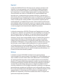
Introduction
Thank you for purchasing the Ubiquiti Networks® FiberPoE
™
.
This Quick Start Guide is designed to guide you through
installation and also includes warranty terms.
Package Contents
Optical Data Transport
for Outdoor PoE Devices
Model: F-POE
FiberPoE
Self-Tapping
Screw (M5)
Serrated
Washer (M5)
Metal Straps
(Qty. 2)
Quick Start
Guide
Installation Requirements
Mounting accessories and drain wire are not included.
Pole-Mounting
• Drill with a 4.5 mm Drill Bit
• 7 mm Socket Wrench or Screwdriver
Wall-Mounting
• (2) Screws (≤ 5 mm Screw Head)
• (1) M5 Machine Screw and Nut
• (1) Drain Wire, Optional (≤ 16 AWG, ≤ 40 cm)
Cables
• Shielded Category 5 (or above) cabling should be used for
all wired Ethernet connections and should be grounded
through the AC ground of the PoE.
We recommend that you protect your networks from
harmful outdoor environments and destructive ESD events
with industrial-grade, shielded Ethernet cable from Ubiquiti
Networks. For more details, visit
www.ubnt.com/toughcable
TERMS OF USE: Shielded Ethernet cable and earth grounding must be used as conditions of
product warranty. TOUGHCable
™
is designed for outdoor installations. It is the customer’s
responsibility to follow local country regulations, including operation within legal frequency
channels, output power, and Dynamic Frequency Selection (DFS) requirements.

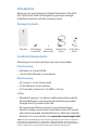
Application Examples
The following are typical use cases for the F-POE.
Data Options
1. Fiber Bridge Two F-POE devices, one at the base and one
at the top of the tower, are used to provide a fiber optic
data link for protection from EMI events that can cause
equipment damage or signal integrity issues.
2. Ethernet-to-Fiber Converter One F-POE at the top of the
tower is used to convert Ethernet to fiber at the radio.
Ethernet
Switch/Router
F-POE
Radio
F-POE
F-POE
Fiber
Switch/Router
Fiber Bridge
Fiber Optic
Data Link
Top of
Tower
Base of
Tower
Fiber Data
Ethernet Data
Ethernet-to-Fiber Converter

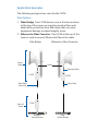
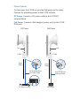
Power Options
On the tower, the F-POE can provide PoE power to the radio.
Options for providing power to the F-POE include:
DC Power Connect a DC power cable to the F-POE DC
terminal block.
PoE Power Connect a PoE adapter (power only) to the F-POE
RJ45 port.
50
50
50
50
F-POE
F-POE
Data
(Fiber)
Data
(Fiber)
DC Power Cable
Ethernet Cable
PoE
PoE
RJ45 DC IN Port
DC Terminal Block
DC Power PoE Power
PoE Source
DC Power Source

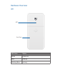
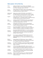
Hardware Overview
LED
Port Cover
LED
LED Color Status
White Power on
Blue Link up
Flashing Blue Activity

Ports
Terminal Block
Ground
Bonding
Point
SFP
DC In
PoE
SFP This hot-swappable SFP port supports 1 Gbps SFP
connections.
VDC Labeled (+) (–), the VDC terminal block provides input or
output power (see the Power Configuration section for details).
DC In This RJ45 port is only used to supply DC input power.
PoE This RJ45 port provides 1000 Mbps data and Power over
Ethernet (PoE) passthrough, and can also be used to supply
input power (see the Power Configuration section for details).
Ground Bonding Point The FiberPoE must be grounded in
one of the following ways:
• Use the Self-Tapping Screw and Serrated Washer to ground
the FiberPoE directly to a grounded metal pole or structure.
• Use an M5 machine screw, the Serrated Washer, and a nut
(not included) to attach a drain wire (not included) that is
connected to a remote grounding block or structure.

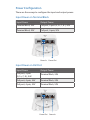
Power Configuration
There are three ways to configure the input and output power:
Input Power on Terminal Block
Input Power Output Power
Terminal Block, 24V PoE port, 2-pair (4,5+; 7, 8-), 24V
Terminal Block, 50V PoE port, 4-pair, 50V
Power In Power Out
Input Power on PoE Port
Input Power Output Power
PoE port, 2-pair
(4,5+; 7, 8-), 24V
Terminal Block, 24V
PoE port, 4-pair, 24V Terminal Block, 24V
PoE port, 4-pair, 50V Terminal Block, 50V
Power In
Power Out

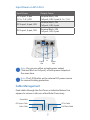
Input Power on DC In Port
Input Power Output Power
DC In port, 2-pair
(4, 5+; 7, 8-), 24V
Terminal Block, 24V
PoE port, 24V, 2-pair (4, 5+; 7, 8-)
DC In port, 4-pair, 24V
Terminal Block, 24V
PoE port, 24V, 4-pair
DC In port, 4-pair, 50V
Terminal Block, 50V
PoE port, 50V, 4-pair
Power
Out
Power
In
Power
Out
Note: You can use either a single power output
(Terminal Block or PoE port), or both power outputs at
the same time.
Note: The F-POE relies on the external DC power source
for current-limiting protection.
Cable Management
Feed cables through the Port Cover as indicated below. Use
nippers to remove a tab over a feed hole if necessary.
Fiber Cable
DC Power Cable
Drain Wire
DC In Cable
PoE/Data Cable

Connect a Drain Wire (Optional)
If a drain wire is used to properly ground the FiberPoE, attach
it to the Ground Bonding Point with an M5 machine screw, the
included Serrated Washer, and nut (not included).
Note: Place the included Serrated Washer between the
drain wire and the Ground Bonding Point.
At the installation site, secure the other end of the drain wire
to a grounded mast, pole, tower, or grounding bar.
Note: The drain wire should be a short as possible and
no longer than one meter in length.

Hardware Installation
Install the FiberPoE either on a pole or a wall. Follow the
appropriate steps for your installation:
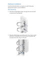
Pole-Mounting
3. Feed the included Metal Straps through the slots located
on the back of the FiberPoE.
4. Wrap the Metal Straps around the pole. Use a 7 mm socket
wrench or screwdriver to turn the screws clockwise and
securely fasten the straps to the pole.

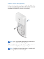
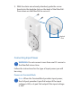
5. Remove the Port Cover by pressing on its center and sliding
it down.
Note: If you are using a drain wire for grounding,
proceed to the Connecting Input Power section.
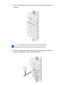
6. Drill a 4.5 mm pilot hole into the pole through the center of
the Ground Bonding Point of the FiberPoE.
4.5 mm
Drill Bit

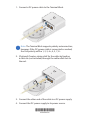
7. Insert the Self-Tapping Screw into the Serrated Washer
(both included) and pilot hole. Securely fasten the screw to
ensure the Ground Bonding Point is bonded to the pole.
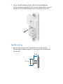
Wall-Mounting
1. Secure two screws (not included) to the wall, spaced
38mm apart. Leave a gap of 3 mm from each screw head
to the wall.
≤ 5 mm
3 mm

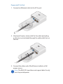
2. With the drain wire already attached, guide the screw
heads into the keyhole slots on the back of the FiberPoE.
Press down on the FiberPoE to secure it.
Keyhole
Slots
Connecting Input Power
WARNING: Do not connect more than one DC source to
the FiberPoE at one time.
Follow the instructions for the type of input power you will
be using:
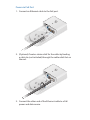
Power via Terminal Block
Note: When the Terminal Block provides input power,
the PoE port provides 2-pair PoE output if the input
voltage is 24V, or 4-pair PoE output if the input voltage
is 50V.

1. Connect a DC power cable to the Terminal Block.
Note:
The Terminal Block supports polarity autocorrection;
however, if the DC power cable is connected as marked,
the PoE polarity will be 1, 2, 3, 6+; 4, 5, 7, 8-.
2. (Optional) Create a strain relief for the cable by feeding
a cable tie (not included) through the cable relief slot on
the reel.
3. Connect the other end of the cable to a DC power supply.
4. Connect the DC power supply to its power source.
*640-00188-03*
640-00188-03

Power via DC In Port
1. Connect an Ethernet cable to the DC In port.
2. (Optional) Create a strain relief for the cable by feeding
a cable tie (not included) through the cable relief slot on
the reel.
3. Connect the other end of the Ethernet cable to a PoE
power source.
Note:
The RJ45 DC In port does not support data
. It
s only
use is to provide power.

Power via PoE Port
1. Connect an Ethernet cable to the PoE port.
2. (Optional) Create a strain relief for the cable by feeding
a cable tie (not included) through the cable relief slot on
the reel.
3. Connect the other end of the Ethernet cable to a PoE
power and data source.

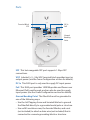
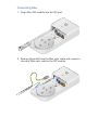
Connecting Fiber
1. Plug a fiber SFP module into the SFP port.
2. Remove the jacket from the fiber optic cable and connect a
strand of fiber optic cable to the SFP module.

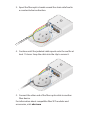
3. Spool the fiber optic strands around the strain relief reel in
a counterclockwise direction.
50
50
4. Continue until the jacketed cable spools onto the reel for at
least 1½ turns. Snap the cable into the clip to secure it.
50
50
5. Connect the other end of the fiber optic cable to another
fiber device.
For information about compatible fiber SFP modules and
accessories, visit: ubnt.com

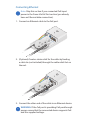
Connecting Ethernet
Note: Skip this section if you connected PoE input
power in the Power Via PoE Port section (you already
have an Ethernet data connection).
1. Connect an Ethernet cable to the PoE port.
50
2. (Optional) Create a strain relief for the cable by feeding
a cable tie (not included) through the cable relief slot on
the reel.
50
50
3. Connect the other end of the cable to an Ethernet device.
WARNING: If the PoE port is providing PoE passthrough
power, ensure that the connected device supports PoE
and the supplied voltage.

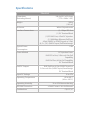
Specifications
FiberPoE
Dimensions
(Excluding Mount)
196.4 x 93.5 x 32.4 mm
( 7.73 x 3.68 x 1.28")
Weight 288 g
(10.2 oz)
Enclosure White Polycarbonate
Interface Connections (1) 1 Gbps SFP Port
(1) DC Terminal Block
(1) DC RJ45 Port, 4-Pair DC Injection
(1) 1000 Mbps Ethernet PoE Port,
4-Pair (24VDC or 50VDC Input) or 2-Pair
(4,5+; 7,8-) (24VDC Input) PoE Passthrough
Typical Power
Consumption
1.5W
Power Method DC Injection From:
RJ45 DC In Port, 2-Pair or 4-Pair PoE
Capability
RJ45 PoE Port, 4-Pair PoE Capability
DC Terminal Block
PoE/DC Output RJ45 PoE Port, 4-Pair (50VDC Input) or
2-Pair or 4-Pair (24VDC Input) Passthrough
DC Terminal Block
Input DC Voltage 16 to 57V
Operating Temperature -40 to 60° C
(-40 to 140° F)
Operating Humidity 10 to 95% Noncondensing
ESD/EMP Protection ± 24KV Contact / Air for Ethernet
Certications CE, FCC, IC
Pagina se încarcă...
Pagina se încarcă...
Pagina se încarcă...
Pagina se încarcă...
Pagina se încarcă...
Pagina se încarcă...
Pagina se încarcă...
Pagina se încarcă...
-
 1
1
-
 2
2
-
 3
3
-
 4
4
-
 5
5
-
 6
6
-
 7
7
-
 8
8
-
 9
9
-
 10
10
-
 11
11
-
 12
12
-
 13
13
-
 14
14
-
 15
15
-
 16
16
-
 17
17
-
 18
18
-
 19
19
-
 20
20
-
 21
21
-
 22
22
-
 23
23
-
 24
24
-
 25
25
-
 26
26
-
 27
27
-
 28
28


Ubiquiti FiberPoE Ghid de inițiere rapidă
- Categorie
- Convertoare media de rețea
- Tip
- Ghid de inițiere rapidă
în alte limbi
- English: Ubiquiti FiberPoE Quick start guide
- italiano: Ubiquiti FiberPoE Guida Rapida
Lucrări înrudite
-
Ubiquiti Edge Point EP-R8 Ghid de inițiere rapidă
-
Ubiquiti edgepoint r6 Ghid de inițiere rapidă
-
-
-
-
-
Ubiquiti ES-24-250W Ghid de inițiere rapidă
-
-
-
Ubiquiti Networks AF-24 Manualul utilizatorului