Phcbi MCO-50AICL-PA-PE Instrucțiuni de utilizare
- Tip
- Instrucțiuni de utilizare

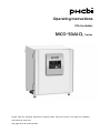
Operating Instructions
CO2 Incubator
Please read the operating instructions carefully before using this product, and keep the operating
instructions for future use.
See page 92 for all model numbers.

CONTENTS
INTRODUCTION .......................................................................................... 4
PRECAUTIONS FOR SAFE OPERATION ................................................... 5
SYMBOLS ON INCUBATOR ...................................................................... 10
ENVIRONMENTAL CONDITIONS ............................................................. 11
INCUBATOR COMPONENTS .................................................................... 12
Unit ........................................................................................................ 12
Control panel ......................................................................................... 14
Remote alarm terminal .......................................................................... 15
INSTALLATION ........................................................................................... 16
Installation site ....................................................................................... 16
Installation .............................................................................................. 17
Connecting a CO2 gas cylinder ............................................................. 19
BEFORE STARTING OPERATION ............................................................ 21
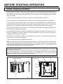
Initial cleaning method ........................................................................... 21
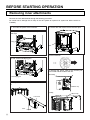
Removing inner attachments ................................................................. 22
Installing inner attachments ................................................................... 23
Filling the humidifying pan ..................................................................... 24
FOR OPTIMAL CULTIVATION ................................................................... 25
Precautions for cultures ......................................................................... 25
Preventing contamination ...................................................................... 26
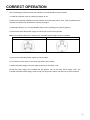
CORRECT OPERATION ............................................................................ 27
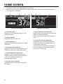
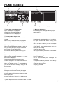
HOME SCREEN ......................................................................................... 28
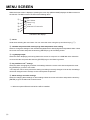
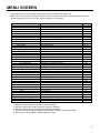
MENU SCREEN ......................................................................................... 30
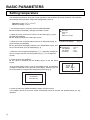
BASIC PARAMETERS ............................................................................... 32
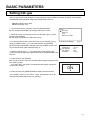
Setting temperature ............................................................................... 32
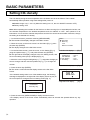
Setting CO2 gas ..................................................................................... 33
Setting CO2 density ............................................................................... 34
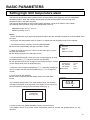
Setting high limit temperature alarm ...................................................... 35
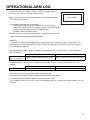
OPERATION/ALARM LOG ......................................................................... 36
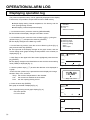
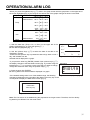
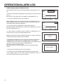
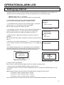
Displaying operation log ........................................................................ 36
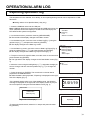
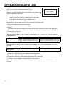
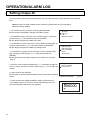
Exporting operation log .......................................................................... 39
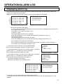
Setting log interval ................................................................................. 41
Setting Unique ID .................................................................................. 42
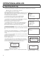
Displaying alarm log .............................................................................. 43
Exporting alarm log ................................................................................ 44
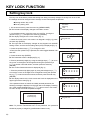
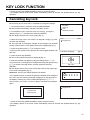
KEY LOCK FUNCTION .............................................................................. 46
Setting key lock ..................................................................................... 46
Cancelling key lock ................................................................................ 47

CONTENTS
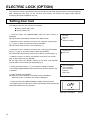
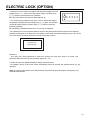
ELECTRIC LOCK (OPTION) ...................................................................... 48
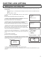
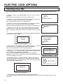
Setting door lock .................................................................................... 48
Setting door lock delay time .................................................................. 49
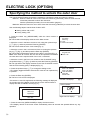
Specifying the method to unlock the outer door .................................... 50
Unlocking the outer door with a User ID ................................................ 51
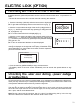
Unlocking the outer door during a power outage or malfunction ........... 51
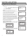
Registering user ID/password ............................................................... 52
Deleting User IDs .................................................................................. 54
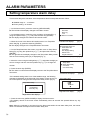
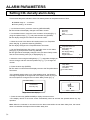
ALARM PARAMETERS .............................................................................. 55
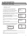
Setting temperature alarm ..................................................................... 55
Setting temperature alarm delay ........................................................... 56
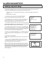
Setting CO2 density alarm ..................................................................... 57
Setting CO2 density alarm delay ............................................................ 58
Setting door alarm delay ........................................................................ 59
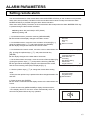
Setting ring back delay .......................................................................... 60
Setting remote alarm ............................................................................. 61
UV LAMP (OPTION) ................................................................................... 62
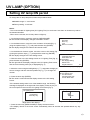
Using UV lamp ....................................................................................... 62
Setting UV lamp ON period ................................................................... 63
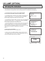
UV lamp life indication ........................................................................... 64
Automatic extension of UV lamp ON period .......................................... 65
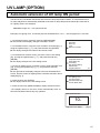
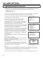
Lighting UV lamp for 24 hours ............................................................... 66
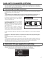
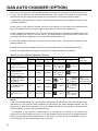
GAS AUTO CHANGER (OPTION) ............................................................. 67
Connecting CO2 gas cylinders ............................................................... 67
Automatic CO2 gas supply line switching .............................................. 67
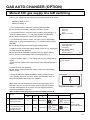
Manual CO2 gas supply line A/B switching ............................................ 69
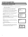
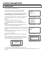
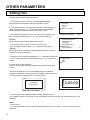
OTHER PARAMETERS .............................................................................. 70
Setting date display format .................................................................... 70
Setting date ........................................................................................... 71
Setting time ............................................................................................ 72
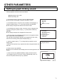
Setting keypad clicking sound ............................................................... 73
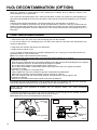
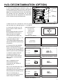
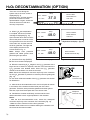
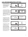
H2O2 DECONTAMINATION (OPTION) ....................................................... 74
H2O2 decontamination ........................................................................... 74
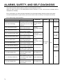
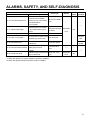
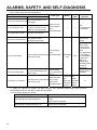
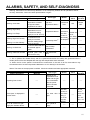
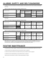
ALARMS, SAFETY, AND SELF-DIAGNOSIS ............................................. 78
ROUTINE MAINTENANCE ........................................................................ 82
TROUBLESHOOTING ................................................................................ 83
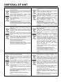
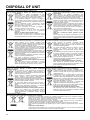
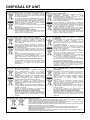
DISPOSAL OF UNIT................................................................................... 85
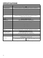
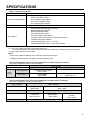
SPECIFICATIONS ...................................................................................... 90
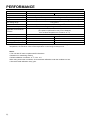
PERFORMANCE ........................................................................................ 92
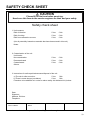
SAFETY CHECK SHEET ........................................................................... 93

INTRODUCTION
■ Read the operating instructions carefully before using the product and follow the instructions for safe
operation.
■ PHC Corporation takes no responsibility for safety if the product is not used as intended or is used with
any procedures other than those given in the operating instructions.
■ Keep the operating instructions in a suitable place so that they can be referred to as necessary.
■ The operating instructions are subject to change without notice for improvement of performance or
function.
■ Contact our sales representative or agent if any page of the operating instructions is lost or the page
order is incorrect, or if the instructions are unclear or inaccurate.
■ No part of the operating instructions may be reproduced in any form without the express written
permission of PHC Corporation.
IMPORTANT NOTICE
PHC Corporation guarantees this product under certain warranty conditions. However, please note that
PHC Corporation shall not be responsible for any loss or damage to the contents of the product.
<Intended Use>
This equipment is designed for cell and tissue culture for laboratory use.

PRECAUTIONS FOR SAFE OPERATION
It is imperative that the user complies with the operating instructions
as they contain important safety advice.
Items and procedures are described so that this unit can be used correctly and safely.
Following these precautions will prevent possible injury to the user and any other person.
Precautions are illustrated in the following way:
WARNING
Warning indicates a potentially hazardous situation which, if not avoided,
could result in serious injury or death.
CAUTION
Failure to observe CAUTION signs could result in injury to personnel and
damage to the unit and associated property.
Symbols have the following meaning;
This symbol means caution.
T
his symbol means an action is prohibited.
T
his symbol means an instruction must be followed.
WARNING
As with any equipment that uses CO2 gas, there is a likelihood of oxygen depletion in the vicinity of the
equipment. It is important that you assess the work site to ensure there is suitable and sufficient
ventilation. If restricted ventilation is suspected, then other methods of ensuring a safe environment must
be considered. These may include atmosphere monitoring and warning devices.
USA Only (Model with a lamp): This product has a lamp that contains mercury. Disposal may be
regulated in your community due to environmental considerations. For disposal or information, please
visit PHC website: https://www.phchd.com.
Contains mercury / Contenu avec mercure
For more information on safe handling
procedures, the measures to be taken in
case of accidental breakage and safe
disposal options visit:
ec.gc.ca/mercure-mercury/.
Dispose of or recycle in accordance with
applicable laws.
Pour plus de renseignements sur les
procédures de manutention sécuritaire, les
mesures à prendre en cas de bris accidentel et
les options d’élimination sécuritaire visitez:
ec.gc.ca/mercure-mercury/.
Mettez au rebut ou recyclez conformément
aux lois applicables.
For the State of California, USA Only:
This product contains a CR Coin Cell Lithium Battery which contains Perchlorate Material – special
handling may apply. See www.dtsc.ca.gov/hazardouswaste/perchlorate.
Be sure to keep the operating instructions in a place that is accessible to users of this unit.

PRECAUTIONS FOR SAFE OPERATION
Do not use the unit outdoors. Exposure to rain may cause leakage and/or electric shock.
Only qualified engineers or service personnel should install the unit. The installation by
unqualified personnel may cause electric shock or fire.
Install the unit in a location capable of bearing the total combined weight (product + optional
accessories + stored items). After installing the unit, be absolutely sure to take precautions to
prevent the unit from falling over. If the unit is installed in a location which is not strong enough or if
the proper precautions are not taken, the unit may fall over and cause injuries.
Do not install the unit where there are high levels of moisture or where it may be splashed with
water. Installing the unit where there are high levels of moisture or where it may be splashed with
water may cause the insulation to deteriorate and give rise to leakage and/or electric shock.
Do not install the unit in a location where flammable or volatile substances are present.
Installing the unit in a location where flammable or volatile substances are present may cause
explosions and/or a fire.
Do not install the unit in a location where corrosive gases such as acids are present. Installing
the unit in a location where corrosive substances are present may cause electric components to
corrode, leading to leakage and/or electric shock due to the deterioration of insulation resulting from
corroded electrical components.
Do not place this unit in a location where it is difficult to disconnect the power supply plug.
Failure to disconnect the power supply plug may cause fire in the event of a problem or malfunction.
Be absolutely sure to earth (ground) the unit in order to prevent electric shock. Failure to earth
the product may give rise to electric shock. If necessary, ask a qualified contractor to do this work.
Do not connect the earth wire to a gas pipe, water pipe, or lightning rod when earthing the
unit. Earthing the unit improperly may give rise to electric shock.
Connect the unit to a power source as indicated on the rating label attached to the unit. Use of
any other voltage or frequency other than that on the rating label may cause fire or electric shock.
Never store volatile or flammable substances in this unit except in a sealed container. Such
substances may cause explosion or fire if they leak.
Never insert metal objects such as pins and wires into any vent, gap or outlet on the unit. This
may cause electric shock or injury by accidental contact with moving parts.
When handling harmful samples (for example, those which consist of toxic, pathogenic, or
radioactive substances), install the unit inside a designated isolation facility. If the unit is
installed in a location which is not an isolation facility, there may be detrimental effects on both people
and the natural environment.
WARNING

PRECAUTIONS FOR SAFE OPERATION
Before proceeding with maintenance or checking of the unit, set the power switch to OFF and
disconnect the power supply plug. Performing the work while power is still flowing to the product or
while the power-supply plug is still connected may give rise to electric shock and/or injury.
Do not touch any electrical parts (such as power supply plug) or operate switches with a wet
hand. This may cause electric shock.
Wear protective gloves and mask during maintenance. Touching or inhaling chemicals or
aerosols from around the unit may be detrimental to health.
Never splash water directly onto the unit as this may cause electric shock or short circuit.
Never put containers with liquid on top of the unit as this may cause electric shock or short circuit if
the liquid is spilled.
Never damage the power supply cord or power supply plug (by breaking, adapting, placing near
a source of heat, bending with force, twisting, pulling, adding weight, or binding). A damaged
power supply cord or power supply plug may cause electric shock, short circuit, or fire.
Do not use the supplied power cord for other electrical equipment. Such power supply cord may
cause fire or electric shock.
Never disassemble, repair, or modify the unit yourself. A high-voltage area is located inside the
unit. Any work carried out by an unauthorized personnel may result in electric shock. Contact our
sales representative or agent for maintenance or repair.
Make sure the power supply plug is pushed fully in. Faulty insertion of the power supply plug may
cause electric shock or fire due to generation of heat. Never use a damaged power supply plug or
loose power outlet.
Disconnect the power supply plug if there is anything wrong with the unit. Continued abnormal
operation may cause electric shock or fire.
Grip the power supply plug when disconnecting the power supply cord from the outlet. Pulling
the power supply cord may cause electric shock or short circuit.
Remove dust from the power supply plug periodically. Dust on the power supply plug may cause
insulation failure due to moisture and thus cause a fire. Disconnect the power supply plug and wipe it
with a dry cloth.
Disconnect the power supply plug before moving the unit. Take care not to damage the power
supply cord. A damaged cord may cause electric shock or fire.
Disconnect the power supply cord when the unit is not in use for long periods. Keeping the unit
connected may cause electric shock, leakage, or fire due to the deterioration of insulation.
WARNING

PRECAUTIONS FOR SAFE OPERATION
If the unit is to be stored unused in an unsupervised area for a long period, ensure that children do
not have access and that doors cannot be closed completely.
Ask a qualified contractor to carry out disassembly and disposal of the unit. Leaving the unit in
a location that can be accessed by third parties may result in unexpected accidents (e.g. the unit may
be used for unintended purposes).
Do not leave the plastic bags used for packing in a place where they can be reached by small
children as this may result in unexpected accidents such as suffocation.
Use the reagent specified by our company for H2O2 decontamination. Using a different H2O2
solution may result in explosion or damage to the incubator.
When performing H2O2 decontamination, securely close the internal and external doors. Failure to
do so may be harmful to health due to leakage of H2O2 gas.
During H2O2 decontamination, plug the access hole with the silicon cap that is provided. Failure to
do so may be harmful to health due to leakage of H2O2 gas.
Always use the removal power supply cord that is provided. Other power supply cord may cause
electric shock or fire.
When using CO2 gas for control, make sure that there is adequate ventilation. Using CO2 gas in a
small room without adequate ventilation may cause gas poisoning or oxygen deprivation. In addition,
when opening the incubator doors, do not directly inhale the air in the chamber.
When connecting a gas cylinder to the incubator, confirm the gas type. Confirm that the
connections are secure and that no gas will leak. Be sure to use the specified pressure. Using
an incorrect gas or pressure may result in explosion or fire, or in gas poisoning or oxygen deprivation
due to gas leak.
Install the incubator in a location with adequate ventilation. If adequate ventilation cannot be
provided, then install an alarm system using CO2 and O2 densitometers.
Do not look directly at UV light. UV light is harmful to the eyes.
Never start H2O2 decontamination when “Warning: UV Bulb Life” is displayed in the message display
area. The UV resolve is not sufficient.
Do not use the unlock key to unlock the outer door during H2O2 decontamination or during H2O2
gas resolve by UV. Doing so may cause harm to health from H2O2 gas leakage.
WARNING

PRECAUTIONS FOR SAFE OPERATION
This unit must be plugged into a dedicated circuit protected by branch circuit breaker.
Use a dedicated power source as indicated on the rating label attached to the unit. A multiple-tap may
cause fire resulting from abnormal heating.
Never store corrosive substances such as acid or alkali in this unit if the container cannot be
sealed. These may cause corrosion of inner components or electric parts.
Check the setting when starting up of operation after power failure or turning off of power
switch. The stored items may be damaged due to the change of setting.
Be careful not to tip over the unit during movement to prevent damage or injury.
Prepare a safety check sheet (copy the last page) when you request any repair or maintenance for
the safety of service personnel.
Wear rubber gloves when handling the H2O2 reagent. Direct contact with the H2O2 reagent may
result in inflammation of the skin.
H2O2 decontamination can be performed only for the chamber and chamber attachments with standard
specifications, and not for any other objects.
Perform H2O2 decontamination with the chamber attachments arranged as specified by our
company. Arranging them in a different way may result in insufficient decontamination.
After H2O2 decontamination has been completed, wear rubber gloves and use a non-woven cloth to
wipe off the residual H2O2 fluid from the bottom of the chamber, any objects that were
decontaminated, and the bottoms of ducts.
Do not climb on top of the incubator or place any object on it. By doing so you may damage the
incubator or knock it over, which may result in injury.
Wear rubber gloves when performing maintenance on the chamber. Failure to wear gloves may
result in cuts or abrasions from sharp edges or corners.
Do not damage the glass or give it a shock. The Inner door in the CO2 Incubator are tempered glass,
but they can be broken or cause injury if they are used incorrectly.
CAUTION

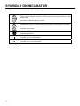
SYMBOLS ON INCUBATOR
The following symbols are attached to the incubator:
Attached to covers that access high-voltage electrical components to prevent electric
shock. Only a qualified engineer or service personnel should be allowed to open
these covers.
Indicates an ultraviolet light (UV) caution.
Indicates that caution is required. Refer to precautions for safe operation for details.
Indicates a hot surface.
Indicates an earthing.
Indicates “ON” for a power switch.
Indicates “OFF” for a power switch.

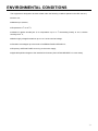
ENVIRONMENTAL CONDITIONS
This equipment is designed to be safe at least under the following conditions (based on the IEC 61010-1):
■ Indoor use;
■ Altitude up to 2,000 m;
■ Temperature 5 oC to 40 oC;
■ Maximum relative humidity 80 % for temperature up to 31 oC decreasing linearly to 50 % relative
humidity at 40 oC;
■ Mains supply voltage fluctuations up to ±10 % of the nominal voltage;
■ Transient overvoltages up to the levels of OVERVOLTAGE CATEGORY II;
■ Temporary OVERVOLTAGES occurring on the mains supply;
■ Applicable pollution degree of the intended environment (POLLUTION DEGREE 2 in most cases);

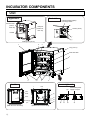
INCUBATOR COMPONENTS
Unit
Appearance
Inside
Control Panel
(P14
P28–29)
Handle
USB port
(P38–40
P44–45)
Leveling feet ( P17)
Hooks ( P18)
With fan cover and duct Without fan cover and duct
Duct
Fan
cover
Interface board (Option)
mounting location
Tray ( P17)
Inner door latch
Fan
Removable power
supply cord port
Humidifying
pan
Lower right side
Back side

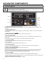
INCUBATOR COMPONENTS
1. Access port: Used when routing cables such as the sensor cable of a measurement instrument into the
chamber. Place the silicon caps on both the outside and inside of the port when the port is not used.
2. Remote alarm terminal: An external alarm unit is connected to this terminal for transferring the alarm
to a remote location. Refer to page 15.
3. Outer door: The outer door is held to the frame with the magnetic seal. The door heater is installed in
the door panel. The direction of the door opening is reversible. Contact our sales representative or agent to
change the door hinge from left to right or vice versa.
4. Inner door: The inner door is made of tempered glass. Do not subject the glass to excessive impact.
5. Tray catches: Trays are inserted to fit these concave parts on the chamber walls.
6. Humidifying pan (Accessory): Fill with sterile distilled water.
7. Switch cover: Prevents shutting down of the unit in case of accidental pressing of the main power
switch.
8. Sample air outlet: This also functions as an internal gas outlet. In normal use, cover this outlet with the
sample air outlet cap.
9. Door switch (Beneath the label): Detects the opening/closing status of the outer door. When the door
is open, the electromagnetic valve for CO2 is closed, the fan is stopped, and the UV lamp*1 is turned off.
10. Electric lock *2: Electric lock is the lock function that automatically locks the outer door when a set amount
of time has elapsed after closing the outer door. Refer to pages 48-54.
11. Key hole *2: Hole for the key to unlock the outer door when locked by the electric lock.
12. CO2 sensor: This sensor measures CO2 density. Handle with care. Refer to page 21.
13. Humidity control bar: Reduces condensation in the unit caused by the external environment and frequent
door openings.
14. Position to mount the H2O2 decontamination connector: Position to mount the optional H2O2
decontamination connector. Refer to page 74.
15. UV lamp *: This UV lamp does not generate ozone. For replacement, contact our sales representative
or agent.
16. Power switch: Main switch for the incubator (ON-“I”, OFF-“O”). It also functions as an overcurrent breaker.
17. Glow starter : Starts the glow for the UV lamp.
18. Connecting port A for CO2 gas pipe: Refer to page 19-20 for gas cylinder connection.
19. Power supply cord cover plate (Accessory): Prevents the power supply cord from being
disconnected.
20. Connecting port B for CO2 gas pipe: When the optional MCO-50GC gas auto-changer is installed, both
ports A and B are available. Refer to pages 67 – 69.
*1 When an optional UV system set MCO-170UVS is installed.
*2 When an optional Electric lock MCO-170EL is installed.

INCUBATOR COMPONENTS
Control panel
When sterilizing and cleaning the control panel, follow the precautions below.
(1) Do not spray liquid on the control panel directly.
(2) When sterilizing and cleaning, wipe the surface using a piece of gauze moistened with a proper
amount of disinfectant
(
the amount that cannot form droplets
)
.
OLED (Organic Light Emitting Diode) display
Current chamber temperature and CO2 density, as well as menu screen and input screens etc. are
displayed.
POWER/ALARM indicator
In normal operation, the green LED lamp lights up, and during alarm condition, the red LED lamp blinks to
indicate alarm.
Up/down/left/right keys ( )
These keys can move the cursor in the screens other than the home screen.
Menu key (MENU/HOME)
On the “home screen”: pressing this key leads the menu screen. It is possible to set various setting on the
menu screen.
On the screen “other than the home screen”: pressing this key leads the home screen.
Cancel key (CANCEL)
On the setting screen, pressing this key switches to the screen of one level up.
H
2O2 key (H2O2) *1
This key initiates H2O2 decontamination (refer to pages 74–77).
Unlock key (UNLOCK) *
This key can unlock the outer door when it is auto-locked by the electric lock (refer to pages 50–51).
Buzzer stop key (BUZZER STOP)
The buzzer is silenced by pressing this key when the buzzer sounds.
Pressing this key stops the buzzer.
However, when the ring back is ON, the buzzer will sound again if the alarm state still continues and preset
amount of time has elapsed after the BUZZER STOP key was pressed. Refer to pages 60 and 78–82.
Note: You cannot silence the buzzer for the high limit temperature alarm.
Enter key (ENTER)
Press this key to select the menu item or to accept the values set during the setting procedures.
*1 When the optional UV system set MCO-170UVS, H2O2 generator MCO-50HP, H2O2 decon kit MCO-50HB
and electric lock MCO-170EL are all installed.
*2 When the optional Electric lock MCO-170EL is installed.

INCUBATOR COMPONENTS
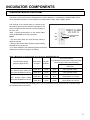
Remote alarm terminal
The alarm of this product can be transferred to a remote location by connecting the external alarm unit to
the remote alarm terminal. For the behaviour of remote alarm output, refer to pages 78–82.
The terminal of the remote alarm is provided at the
back upper right of the unit (see the right figure). The
alarm is output from this terminal. Contact capacity is
DC 30 V, 2 A.
Table 1 shows the behaviour of the remote alarm
when the BUZZER STOP key is pressed.
Notes:
• The door alarm does not work remotely. Refer to
pages 81 and 82.
• Wiring of the remote alarm should be performed by
qualified service personnel.
• It is recommended to use standard signal and interface
cables with a maximum length of 30 meters.
Table 1 Behaviour of remote alarm when pressing BUZZER STOP key
Remote Alarm setting
(Refer to pages 55-61)
Connecting
terminal
Normal
condition
Abnormal condition
(Including during the power outage and when
power suppl
y
cord is disconnected
)
When pressing the BUZZER
STOP ke
y
ON: Remote alarm setting not
linked with BUZZER STOP key
COM.-N.C. Close Open Open (still abnormal)
COM.-N.O. Open Close Close (still abnormal)
OFF: Remote alarm setting
linked with BUZZER STOP key
COM.-N.C. Close Open Close (Return to normal)
COM.-N.O. Open Close Open (Return to normal)
1: In the case of Err01 (CO2 gas empty), Err11, Err12 (CO2 sensor error), and Err18 (UV Lamp Abnormal),
the condition returns to normal.
Remote alarm
terminal

INSTALLATION
Installation site
For correct operation of the incubator, install it in a location with the following conditions.
Normal air environment
Install the incubator in an environment with normal air.
Do not expose to direct sunlight
Do not install the incubator in a location where it will be exposed to direct sunlight. If the incubator is
operated in direct sunlight, performance will be adversely affected.
Separate from heat sources
Do not install the incubator near significant heat sources, such as heaters, boilers, ovens, or autoclaves.
Heat will adversely affect the performance of the incubator.
Ambient temperature at least 5 C lower than set temperature
The control temperature of the incubator is at least 5 C higher than the ambient temperature. For example,
if the chamber is controlled at 37 C, the ambient temperature must be 32 C or less. Do not allow the
ambient temperature to become too high.
Strong and level floor
Select a site with a strong and level floor. If the floor is uneven or the installation is not level, the incubator
will be unstable and this may cause accident or injury. To avoid vibration and noise, always make sure that
the installation is stable. An unstable surface may result in vibration or noise.
Separate from vibration products
Do not install the incubator near vibration products. Vibration may cause culture failure.
Low humidity
Select a site with a relative humidity of 80 %R.H. or lower. Using the incubator in high humidity may result
in current leakage or electric shock.
No inflammable or corrosive gas
Never install the incubator in a location where it will be exposed to inflammable or corrosive gas. Doing so
may result in explosion or fire. In addition, insulation may deteriorate due to corrosion of protective casing,
resulting in current leakage or electric shock.
No falling objects
Do not install the incubator in a location where there is the possibility of objects falling from above. Doing
so may result in damage or accident.

INSTALLATION
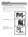
Installation
1. Remove the packing tape and clean up.
Remove all the tapes securing the doors and the inner attachments. Open the doors to ventilate the
chamber for a while. If the outer panels are dirty, use a cloth to wipe them with a diluted neutral detergent
(Undiluted detergent can damage the plastic components. For the dilution, refer to the instructions on the
detergent).
Wipe off the residual detergent with a piece of gauze moistened with water and then wipe off any moisture
with a dry cloth.
Note: Remove the cable tie around the power supply cord to prevent corrosion of the cord coating.
2. Set up the humidifying pan (Fig. 1).
3. Install 2 trays (Fig. 2).
Note: Position the trays with the front edge bent down.
4. Adjust the leveling feet.
Adjust the leveling feet by turning them
anticlockwise until the incubator is level (Fig. 3).
Note: Incubating on a sloping tray may adversely
affect the cultivation.
Fig.1
Fig. 2
Humidifying pan
2 Trays
Fig. 3
Leveling feet
Shrink
Stretch

INSTALLATION
5. Earth the incubator.
Earth the incubator during installation to prevent electric shock. If there is no earth wire at the location,
consult with qualified service personnel.
Notes:
• When an earth must be installed
If an earthed 3-pole outlet is not available, then an earth must be installed. Consult with qualified service
personnel.
• Installing an earth fault circuit breaker
If you must use the incubator in a moist or humid location, then it is recommended that an earth fault circuit
breaker be installed in the power supply circuit (i.e., the power supply at the incubator). Have the circuit
breaker installed by qualified service personnel.
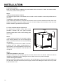
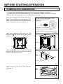
6. In case of double stack or triple stack
For stacking the incubators surely, refer to the
procedure included with the optional double
stacking bracket MCO-170PS or the stacking plate
MCO-50SB.
Notes:
• When stacking incubators, fix the upper incubator
to the wall by passing a wire or chain through the
hooks on the back side of the unit to prevent falling
over (Fig. 4).
• When stacking our other CO2 incubator or O2/CO2
incubator with this product (double-stacking or
triple-stacking), the brackets/plates to be used vary
depending on the combination. Refer to table 8,9
on page 91.
Notes:
• When the incubator is not in use
Empty the water from the humidifying pan and remove moisture from the chamber. Make sure that the
chamber is completely dry before closing the doors. Failure to do so may result in damage.
• Before moving the incubator
Before moving the incubator, empty the water from the humidifying pan, disconnect the power supply plug
from the outlet, and make sure that the power supply cord will not be damaged. Failure to do so may result
in electric shock or fire.
Hooks
Wire
Fig. 4

INSTALLATION
Note: Before connecting a CO2 gas cylinder, read the precautions for safe operation on pages 5–9.
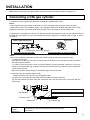
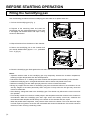
Connecting a CO2 gas cylinder
1. Prepare a CO2 gas cylinder and attach the optional gas regulator MCO-010R.
Notes:
• Use a liquefied-CO2 gas cylinder (at least 99.5 % pure). The siphon (dip tube) type cannot be used.
• When MCO-010R is not available, attach a gas regulator rated at 25 MPa(G) (250 kgf/cm2(G), 3,600
psi(G)) for the primary side, and 0.25 MPa(G) (2.5 kgf/cm2(G), 36 psi(G)) for the secondary side.
2. Connect the connecting port A for the CO2 gas pipe and the gas regulator for the CO2 gas cylinder using the
included gas tube. When CO2 gas auto-changer MCO-50GC (optional) is installed, refer to page 67 for the
connection.
Notes:
• This product employs a tube fitting. Refer to the following steps to attach and remove the tube.
(1) Attaching the tube
Insert the tube all the way to the end so that the tube is secured by the inner locking hook and sealed
with elastic sleeve around it.
* In order to make sure that the tube is securely attached, pull the tube after connection. If the tube
comes off, pull the release ring, and then reconnect the tube and check if it does not become detached.
(2) Removing the tube
Disconnect the tube while pressing on the release ring to remove the tube.
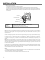
• Connecting to the gas regulator (MCO-010R)
<When connecting to the joint for the gas regulator tube>
(1) Attach the conversion joint that came with the incubator unit to the gas tube.
(2) Connect between the joints using the connection tube, and then secure the connection with the
tube bands.
Preparation
of parts
(Reference)
Connection tube: φ6 inner diameter/soft polyurethane tube
Tube bands
Lower right side of unit
Connecting port for GAS tube Enlarged illustration of the port (
tube fitting)
Connecting port A for CO2 gas pipe Pull
Release ring
Push
Gas regulator
Conversion joint (included accessory)
Tube bands
Connection tube
Gas tube (included accessory)
Release ring

INSTALLATION
<When using the tube fitting>
(1) Remove the hose joint from the gas regulator.
(2) Attach the conversion bush using the packing or seal tape and then, attach the tube fitting.
(3) Connect the gas regulator and the incubator using the gas tube that came with the incubator unit.
Note: Wind the seal tape around the thread part only. Make sure that the seal tape does not stick out
of the thread.
Preparation
of parts
(Reference)
Tube fitting: female straight, adaptive tube OD6mm, Rc1/8
Conversion bush: bush A M12x1, R1/8
Packing: 6A (ID13mm x OD18mm) or seal tape
Note: If the CO2 gas is supplied to multiple CO2 incubators from a single gas cylinder, a CO2 solid will be
formed in the gas regulator. Then, the gas regulator safety valve will actuate, and there may be an
explosive sound.
3. After connecting the gas tube, make sure that no gas is leaking (ex. by using a gas leak detector spray).
4. Set the CO2 gas on the secondary side to 0.03 MPa(G)–0.1 MPa(G) (0.3 kgf/cm2(G)–1 kgf/cm2(G),
4.4 psi(G)–14.5 psi(G)) for gas injection. Recommended pressure: 0.03 MPa(G) (0.3 kgf/cm2(G), 4.4
psi(G)).
Note: Do not set the pressure on the secondary side too high. As the pressure increases, the CO2 gas
density will vary widely. Excessive pressure may cause gas supply lines inside the incubator to come loose,
which may result in gas poisoning or oxygen deprivation due to leaking gas. If gas lines come loose, the
incubator must be repaired.
5. When there is no CO2 gas left and the CO2 gas empty alarm is activated, replace the empty gas cylinder.
Note: When the optional gas auto-changer MCO-50GC is installed, it automatically switches the empty
CO2 gas supply line to the other. Refer to pages 67–68.
Notes:
ꞏ The gas lines connected to the incubator will degrade over time. If any deterioration or abnormalities are
found during inspection, replace the lines immediately.
ꞏ Close the valve of the CO2 gas cylinder when the CO2 gas is not in use.
Release ring
Conversion bush
Tube fitting
Packing
Pagina se încarcă ...
Pagina se încarcă ...
Pagina se încarcă ...
Pagina se încarcă ...
Pagina se încarcă ...
Pagina se încarcă ...
Pagina se încarcă ...
Pagina se încarcă ...
Pagina se încarcă ...
Pagina se încarcă ...
Pagina se încarcă ...
Pagina se încarcă ...
Pagina se încarcă ...
Pagina se încarcă ...
Pagina se încarcă ...
Pagina se încarcă ...
Pagina se încarcă ...
Pagina se încarcă ...
Pagina se încarcă ...
Pagina se încarcă ...
Pagina se încarcă ...
Pagina se încarcă ...
Pagina se încarcă ...
Pagina se încarcă ...
Pagina se încarcă ...
Pagina se încarcă ...
Pagina se încarcă ...
Pagina se încarcă ...
Pagina se încarcă ...
Pagina se încarcă ...
Pagina se încarcă ...
Pagina se încarcă ...
Pagina se încarcă ...
Pagina se încarcă ...
Pagina se încarcă ...
Pagina se încarcă ...
Pagina se încarcă ...
Pagina se încarcă ...
Pagina se încarcă ...
Pagina se încarcă ...
Pagina se încarcă ...
Pagina se încarcă ...
Pagina se încarcă ...
Pagina se încarcă ...
Pagina se încarcă ...
Pagina se încarcă ...
Pagina se încarcă ...
Pagina se încarcă ...
Pagina se încarcă ...
Pagina se încarcă ...
Pagina se încarcă ...
Pagina se încarcă ...
Pagina se încarcă ...
Pagina se încarcă ...
Pagina se încarcă ...
Pagina se încarcă ...
Pagina se încarcă ...
Pagina se încarcă ...
Pagina se încarcă ...
Pagina se încarcă ...
Pagina se încarcă ...
Pagina se încarcă ...
Pagina se încarcă ...
Pagina se încarcă ...
Pagina se încarcă ...
Pagina se încarcă ...
Pagina se încarcă ...
Pagina se încarcă ...
Pagina se încarcă ...
Pagina se încarcă ...
Pagina se încarcă ...
Pagina se încarcă ...
Pagina se încarcă ...
Pagina se încarcă ...
Pagina se încarcă ...
Pagina se încarcă ...
-
 1
1
-
 2
2
-
 3
3
-
 4
4
-
 5
5
-
 6
6
-
 7
7
-
 8
8
-
 9
9
-
 10
10
-
 11
11
-
 12
12
-
 13
13
-
 14
14
-
 15
15
-
 16
16
-
 17
17
-
 18
18
-
 19
19
-
 20
20
-
 21
21
-
 22
22
-
 23
23
-
 24
24
-
 25
25
-
 26
26
-
 27
27
-
 28
28
-
 29
29
-
 30
30
-
 31
31
-
 32
32
-
 33
33
-
 34
34
-
 35
35
-
 36
36
-
 37
37
-
 38
38
-
 39
39
-
 40
40
-
 41
41
-
 42
42
-
 43
43
-
 44
44
-
 45
45
-
 46
46
-
 47
47
-
 48
48
-
 49
49
-
 50
50
-
 51
51
-
 52
52
-
 53
53
-
 54
54
-
 55
55
-
 56
56
-
 57
57
-
 58
58
-
 59
59
-
 60
60
-
 61
61
-
 62
62
-
 63
63
-
 64
64
-
 65
65
-
 66
66
-
 67
67
-
 68
68
-
 69
69
-
 70
70
-
 71
71
-
 72
72
-
 73
73
-
 74
74
-
 75
75
-
 76
76
-
 77
77
-
 78
78
-
 79
79
-
 80
80
-
 81
81
-
 82
82
-
 83
83
-
 84
84
-
 85
85
-
 86
86
-
 87
87
-
 88
88
-
 89
89
-
 90
90
-
 91
91
-
 92
92
-
 93
93
-
 94
94
-
 95
95
-
 96
96


Phcbi MCO-50AICL-PA-PE Instrucțiuni de utilizare
- Tip
- Instrucțiuni de utilizare
în alte limbi
Lucrări conexe
-
Phcbi MCO-170AICL Instrucțiuni de utilizare
-
-
-
-
-
-
-
-
-
Alte documente
-
Dometic TwinBoost4000, TwinBoost4000E, TwinBoost6000, TwinBoost6000E Manual de utilizare
-
Dometic CH4000 Manual de utilizare
-
JBL PROFLORA Manual de utilizare
-
-
Medtronic Filterline Manual de utilizare
-
Electrolux EC4201AOW Manual de utilizare
-
Samsung AC100RXADKG/EU Manual de utilizare
-
Daikin ARXS50G3V1B Ghid de instalare