
www.mellanox.com
Mellanox 1U Switch Systems Hardware User
Manual
Models: SX1710 and SX1410
Rev 1.6

Document Number: MLNX-15-4242
Rev 1.6
Mellanox Technologies
2
Mellanox Technologies
350 Oakmead Parkway Suite 100
Sunnyvale, CA 94085
U.S.A.
www.mellanox.com
Tel: (408) 970-3400
Fax: (408) 970-3403
© Copyright 2016. Mellanox Technologies LTD. All Rights Reserved.
Mellanox®, Mellanox logo, BridgeX®, CloudX logo, Connect-IB®, ConnectX®, CoolBox®, CORE-Direct®, EZchip®,
EZchip logo, EZappliance®, EZdesign®, EZdriver®, EZsystem®, GPUDirect®, InfiniHost®, InfiniScale®, Kotura®, Kotura
logo, Mellanox Federal Systems®, Mellanox Open Ethernet®, Mellanox ScalableHPC®, Mellanox Connect Accelerate
Outperform logo, Mellanox Virtual Modular Switch®, MetroDX®, MetroX®, MLNX-OS®, NP-1c®, NP-2®, NP-3®, Open
Ethernet logo, PhyX®, SwitchX®, Tilera®, Tilera logo, TestX®, The Generation of Open Ethernet logo, UFM®, Virtual
Protocol Interconnect®, Voltaire® and Voltaire logo are registered trademarks of Mellanox Technologies, Ltd.
All other trademarks are property of their respective owners.
For the most updated list of Mellanox trademraks, visit http://www.mellanox.com/page/trademarks
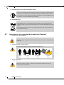
NOTE:
THIS HARDWARE, SOFTWARE OR TEST SUITE PRODUCT (“PRODUCT(S)”) AND ITS RELATED
DOCUMENTATION ARE PROVIDED BY MELLANOX TECHNOLOGIES “AS-IS” WITH ALL FAULTS OF ANY
KIND AND SOLELY FOR THE PURPOSE OF AIDING THE CUSTOMER IN TESTING APPLICATIONS THAT USE
THE PRODUCTS IN DESIGNATED SOLUTIONS. THE CUSTOMER'S MANUFACTURING TEST ENVIRONMENT
HAS NOT MET THE STANDARDS SET BY MELLANOX TECHNOLOGIES TO FULLY QUALIFY THE PRODUCT(S)
AND/OR THE SYSTEM USING IT. THEREFORE, MELLANOX TECHNOLOGIES CANNOT AND DOES NOT
GUARANTEE OR WARRANT THAT THE PRODUCTS WILL OPERATE WITH THE HIGHEST QUALITY. ANY
EXPRESS OR IMPLIED WARRANTIES, INCLUDING, BUT NOT LIMITED TO, THE IMPLIED WARRANTIES OF
MERCHANTABILITY, FITNESS FOR A PARTICULAR PURPOSE AND NONINFRINGEMENT ARE DISCLAIMED.
IN NO EVENT SHALL MELLANOX BE LIABLE TO CUSTOMER OR ANY THIRD PARTIES FOR ANY DIRECT,
INDIRECT, SPECIAL, EXEMPLARY, OR CONSEQUENTIAL DAMAGES OF ANY KIND (INCLUDING, BUT NOT
LIMITED TO, PAYMENT FOR PROCUREMENT OF SUBSTITUTE GOODS OR SERVICES; LOSS OF USE, DATA,
OR PROFITS; OR BUSINESS INTERRUPTION) HOWEVER CAUSED AND ON ANY THEORY OF LIABILITY,
WHETHER IN CONTRACT, STRICT LIABILITY, OR TORT (INCLUDING NEGLIGENCE OR OTHERWISE)
ARISING IN ANY WAY FROM THE USE OF THE PRODUCT(S) AND RELATED DOCUMENTATION EVEN IF
ADVISED OF THE POSSIBILITY OF SUCH DAMAGE.

Rev 1.4
Mellanox Technologies
1
Table of Contents
Chapter 1 Introduction to Mellanox SX1710 and SX1410 Systems . . . . . . . . . . . . . . . . 7
1.1 Overview . . . . . . . . . . . . . . . . . . . . . . . . . . . . . . . . . . . . . . . . . . . . . . . . . . . . . . . . 7
1.2 Speed and Switching . . . . . . . . . . . . . . . . . . . . . . . . . . . . . . . . . . . . . . . . . . . . . . . 8
1.3 Management Interfaces, PSUs and Fans . . . . . . . . . . . . . . . . . . . . . . . . . . . . . . . . 8
1.4 Features . . . . . . . . . . . . . . . . . . . . . . . . . . . . . . . . . . . . . . . . . . . . . . . . . . . . . . . . . 8
1.5 Certifications . . . . . . . . . . . . . . . . . . . . . . . . . . . . . . . . . . . . . . . . . . . . . . . . . . . . . 8
1.6 Ordering Information. . . . . . . . . . . . . . . . . . . . . . . . . . . . . . . . . . . . . . . . . . . . . . . 9
Chapter 2 Installation . . . . . . . . . . . . . . . . . . . . . . . . . . . . . . . . . . . . . . . . . . . . . . . . . . . . 10
2.1 Safety Warnings. . . . . . . . . . . . . . . . . . . . . . . . . . . . . . . . . . . . . . . . . . . . . . . . . . 10
2.2 System Installation and Initialization . . . . . . . . . . . . . . . . . . . . . . . . . . . . . . . . . 10
2.3 Air Flow . . . . . . . . . . . . . . . . . . . . . . . . . . . . . . . . . . . . . . . . . . . . . . . . . . . . . . . 11
2.4 Package Contents. . . . . . . . . . . . . . . . . . . . . . . . . . . . . . . . . . . . . . . . . . . . . . . . . 12
2.5 Mounting Options . . . . . . . . . . . . . . . . . . . . . . . . . . . . . . . . . . . . . . . . . . . . . . . . 12
2.5.1 Static Rail Kit . . . . . . . . . . . . . . . . . . . . . . . . . . . . . . . . . . . . . . . . . . . . . . . . . . . . 13
2.5.2 Telescopic Rail Kit . . . . . . . . . . . . . . . . . . . . . . . . . . . . . . . . . . . . . . . . . . . . . . . . 17
2.6 Cable Installation. . . . . . . . . . . . . . . . . . . . . . . . . . . . . . . . . . . . . . . . . . . . . . . . . 24
2.6.1 Breakout Cables and Adapters . . . . . . . . . . . . . . . . . . . . . . . . . . . . . . . . . . . . . . . 24
2.7 SFP+ Removal Tool . . . . . . . . . . . . . . . . . . . . . . . . . . . . . . . . . . . . . . . . . . . . . . 28
2.8 Initial Power On. . . . . . . . . . . . . . . . . . . . . . . . . . . . . . . . . . . . . . . . . . . . . . . . . . 29
2.9 System Bring-Up . . . . . . . . . . . . . . . . . . . . . . . . . . . . . . . . . . . . . . . . . . . . . . . . . 30
2.9.1 Configuring Network Attributes . . . . . . . . . . . . . . . . . . . . . . . . . . . . . . . . . . . . . 30
2.10 FRU Replacements . . . . . . . . . . . . . . . . . . . . . . . . . . . . . . . . . . . . . . . . . . . . . . . 34
2.10.1 Power Supply . . . . . . . . . . . . . . . . . . . . . . . . . . . . . . . . . . . . . . . . . . . . . . . . . . . . 34
2.10.2 Fans . . . . . . . . . . . . . . . . . . . . . . . . . . . . . . . . . . . . . . . . . . . . . . . . . . . . . . . . . . . . 36
Chapter 3 Interfaces . . . . . . . . . . . . . . . . . . . . . . . . . . . . . . . . . . . . . . . . . . . . . . . . . . . . . 37
3.1 Supported Interfaces . . . . . . . . . . . . . . . . . . . . . . . . . . . . . . . . . . . . . . . . . . . . . . 37
3.1.1 Data Interfaces . . . . . . . . . . . . . . . . . . . . . . . . . . . . . . . . . . . . . . . . . . . . . . . . . . . 37
3.1.2 Speed. . . . . . . . . . . . . . . . . . . . . . . . . . . . . . . . . . . . . . . . . . . . . . . . . . . . . . . . . . . 37
3.1.3 RS232 (Console) . . . . . . . . . . . . . . . . . . . . . . . . . . . . . . . . . . . . . . . . . . . . . . . . . . 37
3.1.4 Management . . . . . . . . . . . . . . . . . . . . . . . . . . . . . . . . . . . . . . . . . . . . . . . . . . . . . 37
3.1.5 USB. . . . . . . . . . . . . . . . . . . . . . . . . . . . . . . . . . . . . . . . . . . . . . . . . . . . . . . . . . . . 38
3.1.6 Reset Button . . . . . . . . . . . . . . . . . . . . . . . . . . . . . . . . . . . . . . . . . . . . . . . . . . . . . 38
3.1.7 Status and Port LEDs . . . . . . . . . . . . . . . . . . . . . . . . . . . . . . . . . . . . . . . . . . . . . . 38
3.2 LEDs . . . . . . . . . . . . . . . . . . . . . . . . . . . . . . . . . . . . . . . . . . . . . . . . . . . . . . . . . . 39
3.2.1 LED Notifications . . . . . . . . . . . . . . . . . . . . . . . . . . . . . . . . . . . . . . . . . . . . . . . . . 39
3.3 Inventory Information . . . . . . . . . . . . . . . . . . . . . . . . . . . . . . . . . . . . . . . . . . . . . 44
Chapter 4 Software Management. . . . . . . . . . . . . . . . . . . . . . . . . . . . . . . . . . . . . . . . . . . 46
4.1 Upgrading Software . . . . . . . . . . . . . . . . . . . . . . . . . . . . . . . . . . . . . . . . . . . . . . 46
4.1.1 MLNX-OS Software Upgrade . . . . . . . . . . . . . . . . . . . . . . . . . . . . . . . . . . . . . . . 46
4.1.2 Switch Firmware Update. . . . . . . . . . . . . . . . . . . . . . . . . . . . . . . . . . . . . . . . . . . . 46
Chapter 5 Troubleshooting . . . . . . . . . . . . . . . . . . . . . . . . . . . . . . . . . . . . . . . . . . . . . . . . 47

Rev 1.4
Mellanox Technologies
2
5.1 Troubleshooting Instructions. . . . . . . . . . . . . . . . . . . . . . . . . . . . . . . . . . . . . . . . 47
Chapter 6 Specifications . . . . . . . . . . . . . . . . . . . . . . . . . . . . . . . . . . . . . . . . . . . . . . . . . . 49
6.1 SX1710 Series . . . . . . . . . . . . . . . . . . . . . . . . . . . . . . . . . . . . . . . . . . . . . . . . . . . 49
6.2 SX1410 Series . . . . . . . . . . . . . . . . . . . . . . . . . . . . . . . . . . . . . . . . . . . . . . . . . . . 50

Rev 1.4
Mellanox Technologies
1
List of Figures
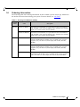
Table 1: Revision History Table 4
Table 2: References 5
Table 3: Speed and Switching Capabilities 8
Table 4: Management Interfaces, PSUs and Fans 8
Table 5: Ordering Part Numbers (OPNs) 9
Table 6: Air Flow Color Legend 11
Table 7: Installation Kit 13
Table 8: Installation Kit 17
Table 9: Port Splitting Options 25
Table 10: Serial Terminal Program Configuration 30
Table 11: Configuration Wizard Session 31
Table 12: Configuration Wizard Session - Static IP Configuration 32
Table 13: LEDs Symbols 39
Table 14: System Status LED Assignments 40
Table 15: Fan Status Rear LED Assignments (One LED per Fan) 40
Table 16: Power Supply Unit Status Front LED Assignments 41
Table 17: Power Supply Unit Status Rear LED Assignments 42
Table 18: Bad Port LED Assignments 42
Table 19: Port LEDs in Ethernet System Mode 43
Table 20: Troubleshooting 47
Table 21: SX1710 Specifications 49
Table 22: SX1410 Specifications 50
Table 23: OPNs for Replacement Parts 51

Rev 1.4
Mellanox Technologies
1
List of Figures
Figure 1: SX1710 Front Side View . . . . . . . . . . . . . . . . . . . . . . . . . . . . . . . . . . . . . . . . . . . . . . . . . .7
Figure 2: SX1410 Front Side View . . . . . . . . . . . . . . . . . . . . . . . . . . . . . . . . . . . . . . . . . . . . . . . . . .7
Figure 3: SX1710/SX1410 Rear Side View . . . . . . . . . . . . . . . . . . . . . . . . . . . . . . . . . . . . . . . . . . . .7
Figure 4: Air Flow Direction Marking - Power Side Inlet to Connector Side Outlet . . . . . . . . . . .12
Figure 5: Air Flow Direction Marking - Connector Side Inlet to Power Side Outlet . . . . . . . . . . .12
Figure 6: Rack Rail Kit Parts . . . . . . . . . . . . . . . . . . . . . . . . . . . . . . . . . . . . . . . . . . . . . . . . . . . . . .13
Figure 7: Installation Options . . . . . . . . . . . . . . . . . . . . . . . . . . . . . . . . . . . . . . . . . . . . . . . . . . . . . .14
Figure 8: Attaching the Rails to the Chassis . . . . . . . . . . . . . . . . . . . . . . . . . . . . . . . . . . . . . . . . . .15
Figure 9: Attaching the Brackets to the Chassis . . . . . . . . . . . . . . . . . . . . . . . . . . . . . . . . . . . . . . .15
Figure 10: Installing the Cage Nuts . . . . . . . . . . . . . . . . . . . . . . . . . . . . . . . . . . . . . . . . . . . . . . . . . .16
Figure 11: Attaching the Brackets to the Rack . . . . . . . . . . . . . . . . . . . . . . . . . . . . . . . . . . . . . . . . .16
Figure 12: Sliding the Blades in the Rails . . . . . . . . . . . . . . . . . . . . . . . . . . . . . . . . . . . . . . . . . . . . .17
Figure 13: Rack Rail Kit Parts . . . . . . . . . . . . . . . . . . . . . . . . . . . . . . . . . . . . . . . . . . . . . . . . . . . . . .19
Figure 14: Rails Separation . . . . . . . . . . . . . . . . . . . . . . . . . . . . . . . . . . . . . . . . . . . . . . . . . . . . . . . .19
Figure 15: Installing the Cage Nuts . . . . . . . . . . . . . . . . . . . . . . . . . . . . . . . . . . . . . . . . . . . . . . . . . .20
Figure 16: Mounting the Outer Rails into the Rack . . . . . . . . . . . . . . . . . . . . . . . . . . . . . . . . . . . . . .20
Figure 17: Attaching the Inner Rails to the Chassis . . . . . . . . . . . . . . . . . . . . . . . . . . . . . . . . . . . . . .21
Figure 18: Securing the Chassis in the Inner Rails . . . . . . . . . . . . . . . . . . . . . . . . . . . . . . . . . . . . . .21
Figure 19: Sliding the Switch into the Rack . . . . . . . . . . . . . . . . . . . . . . . . . . . . . . . . . . . . . . . . . . .22
Figure 20: Pulling the Unit Outwards . . . . . . . . . . . . . . . . . . . . . . . . . . . . . . . . . . . . . . . . . . . . . . . .22
Figure 21: Locking Mechanism . . . . . . . . . . . . . . . . . . . . . . . . . . . . . . . . . . . . . . . . . . . . . . . . . . . . .23
Figure 22: Cable Orientation . . . . . . . . . . . . . . . . . . . . . . . . . . . . . . . . . . . . . . . . . . . . . . . . . . . . . . .24
Figure 23: Breakout or Fanout Cable . . . . . . . . . . . . . . . . . . . . . . . . . . . . . . . . . . . . . . . . . . . . . . . . .25
Figure 24: SX1710 Port Splitting Options . . . . . . . . . . . . . . . . . . . . . . . . . . . . . . . . . . . . . . . . . . . . .25
Figure 25: SX1710 Port Splitting Options . . . . . . . . . . . . . . . . . . . . . . . . . . . . . . . . . . . . . . . . . . . . .27
Figure 26: SFP+ Removal and Insertion Tool . . . . . . . . . . . . . . . . . . . . . . . . . . . . . . . . . . . . . . . . . .28
Figure 27: System Status LEDs 5 Minutes After Power On . . . . . . . . . . . . . . . . . . . . . . . . . . . . . . .29
Figure 28: Two Power Inlets - Electric Caution Notifications . . . . . . . . . . . . . . . . . . . . . . . . . . . . .30
Figure 29: PS Unit Pulled Out . . . . . . . . . . . . . . . . . . . . . . . . . . . . . . . . . . . . . . . . . . . . . . . . . . . . . .35
Figure 30: Fan Module Latches . . . . . . . . . . . . . . . . . . . . . . . . . . . . . . . . . . . . . . . . . . . . . . . . . . . . .36
Figure 31: System Status LEDs - Front and Rear Sides . . . . . . . . . . . . . . . . . . . . . . . . . . . . . . . . . .39
Figure 32: Fan Status LED- Front and Rear Sides . . . . . . . . . . . . . . . . . . . . . . . . . . . . . . . . . . . . . . .40
Figure 33: Power Status LED . . . . . . . . . . . . . . . . . . . . . . . . . . . . . . . . . . . . . . . . . . . . . . . . . . . . . .41
Figure 34: Rear Side Panel . . . . . . . . . . . . . . . . . . . . . . . . . . . . . . . . . . . . . . . . . . . . . . . . . . . . . . . . .41
Figure 35: SX1410 and SX1710 QSFP28 Port LEDs . . . . . . . . . . . . . . . . . . . . . . . . . . . . . . . . . . . .43

Rev 1.4
Mellanox Technologies
2
Figure 36: SX1410 SFP28 Port LEDs . . . . . . . . . . . . . . . . . . . . . . . . . . . . . . . . . . . . . . . . . . . . . . . .43
Figure 37: SX1710 Pull-out Tab . . . . . . . . . . . . . . . . . . . . . . . . . . . . . . . . . . . . . . . . . . . . . . . . . . . .44
Figure 38: SX1410 Pull-out Tab . . . . . . . . . . . . . . . . . . . . . . . . . . . . . . . . . . . . . . . . . . . . . . . . . . . .44
Figure 39: QSFP Connector Male and Female Views . . . . . . . . . . . . . . . . . . . . . . . . . . . . . . . . . . . .54
Figure 40: Rear View of Module With Pin Placement . . . . . . . . . . . . . . . . . . . . . . . . . . . . . . . . . . .55
Figure 41: RJ45 to DB9 Harness Pinout . . . . . . . . . . . . . . . . . . . . . . . . . . . . . . . . . . . . . . . . . . . . . .57

Rev 1.6
Mellanox Technologies
4
Revision History
Table 1 - Revision History Table
Date Revision Description
November 2016 1.6 Updated:
• “Specifications”
March 2016 1.5 Updated “Specifications”
Added Taiwan BSMI Class A Statement in Safety Warnings
October 2015 1.4 Added SX1410
May 2015 1.3 Added Hebrew safety warnings
April 2015 1.2 Added “Telescopic Rail Kit”
January 2015 1.1 Minor formatting edits
January 2015 1.0 Initial release of the first edition

Rev 1.6
Mellanox Technologies
5
About this Manual
This manual describes the installation and basic use of the Mellanox Ethernet systems.
Intended Audience
This manual is intended for IT managers and system administrators.
References
Conventions
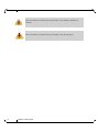
The following icons are used throughout this document to indicate information that is important
to the user.
Table 2 - References
Document Description
MLNX-OS® User Manual This document contains information regarding the configuration and man-
agement of the MLNX-OS software. See http://www.mellanox.com/page/
mlnx_os.
This icon makes recommendations to the user.
This icon indicates information that is helpful to the user.

Rev 1.6
Mellanox Technologies
6
This icon indicates a situation that can potentially cause damage to hardware or
software.
This icon indicates a situation that can potentially cause personal injury.

Introduction to Mellanox SX1710 and SX1410 Systems Rev 1.6
Mellanox Technologies
7
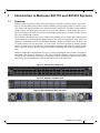
1 Introduction to Mellanox SX1710 and SX1410 Systems
1.1 Overview
Mellanox Ethernet System Family delivers the highest performance and port density with a com-
plete system and fabric management solution enabling converged data centers to operate at any
scale while reducing operational costs and infrastructure complexity. The SX1710 Top-of-Rack
(TOR) system and Aggregation Switch has 36 ports and supports 1/10/40/56Gb/s per port. It
allows IT managers to build cost-effective and scalable system fabrics for small to large clusters
up to 10's-of-thousands of nodes.
The SX1410 is the optimal top of rack (TOR) switch with 48 port of 10GbE and 12 uplink ports
of 40/56GbE for non-blocking throughput between the rack and aggregation layer. Based on
Mellanox’s SwitchX®-2 silicon and advanced hardware design this switch packs 48 SFP+ and
12 QSFP interfaces in an ultra-dense 1U form factor. The SX1410 features industry leading
latency of 250ns and power efficiency while providing optimal performance for enterprise data
center, financial services, Web 2.0, high performance computing and cloud computing applica
-
tions.
Mellanox makes fabric management as easy as it can by providing the lowest latency and highest
bandwidth. This allows IT managers to deal with serving the company's business needs, while
solving typical networking issues such as congestion and the inefficiencies generated by adding
unnecessary rules and limitations when the network resources are sufficient.
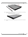
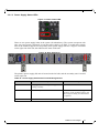
Figure 1: SX1710 Front Side View
Figure 2: SX1410 Front Side View
Figure 3: SX1710/SX1410 Rear Side View

Introduction to Mellanox SX1710 and SX1410 Systems
Rev 1.6
Mellanox Technologies
8
1.2 Speed and Switching
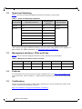
Table 3 describes maximum throughput and interface speed per system model.
*The system can support different interfaces and speed rates using QSFP to SFP adapters or
hybrid cables. For further information, see
“Breakout Cables and Adapters”.
1.3 Management Interfaces, PSUs and Fans
Table 4 lists the various management interfaces, PSUs and fans per system model.
1.4 Features
For a full feature list, please refer to the system’s product brief. Go to http://www.mellanox.com.
In the main menu, click on Products--> Ethernet Switch Systems, and select the desired product
page.
1.5 Certifications
The list of certifications (such as EMC, Safety and others) per system for different regions of the
world is located on the Mellanox website at:
http://www.mellanox.com/page/environmental_compliance
Table 3 - Speed and Switching Capabilities
System Model 10GbE SFP+ Interfaces*
40/56GbE QSFP+
Interfaces*
Max Throughput
SX1710 N/A 36 4.032Tb/s
SX1410 48 12 2.3Tb/s
52 10
56 8
58 6
60 4
62 2
64 N/A
Table 4 - Management Interfaces, PSUs and Fans
System Model USB MGT Console PSU Fan
SX1710 Rear Rear (2 ports) Rear Yes Yes
SX1410 Rear Rear (2 ports) Rear Yes Yes

Introduction to Mellanox SX1710 and SX1410 Systems Rev 1.6
Mellanox Technologies
9
1.6 Ordering Information
The following table lists ordering information for the available systems. Please pay attention to
the airflow direction when ordering your system. For more details, see
“Air Flow”.
Table 5 - Ordering Part Numbers (OPNs)
System
Model
OPN Description
SX1710 MSX1710-BS2F2 SwitchX®-2 based 40GbE, 1U Open Ethernet Switch with MLNX-
OS, 36 QSFP+ ports, 2 Power Supplies (AC), x86 dual core, standard
depth, rear to front airflow, Rail kit, RoHS6
MSX1710-BS2R2 SwitchX®-2 based 40GbE, 1U Open Ethernet Switch with MLNX-
OS, 36 QSFP+ ports, 2 Power Supplies (AC), x86 dual core, standard
depth, front to rear airflow, Rail kit, RoHS6
SX1410 MSX1410-BB2F2 Switch-X™-2 based 10GbE/40GbE Switch, 1U Open Ethernet
switch with MLNX-OS, 48 SFP+ ports, 12 QSFP+ ports, 2 power
supplies (AC), x86 dual core, Short depth, P2C airflow, Rail Kit,
RoHS6
MSX1410-BB2R2 Switch-X™-2 based 10GbE/40GbE Switch, 1U Open Ethernet
switch with MLNX-OS, 48 SFP+ ports, 12 QSFP+ ports, 2 power
supplies (AC), x86 dual core, Short depth, C2P airflow, Rail Kit,
RoHS6
MSX1410-BBBF2 SwitchX®-2 based 10GbE/40GbE Switch, 1U Open Ethernet switch
with MLNX-OS, 48 SFP+ ports, 12 QSFP+ ports, 2 power supplies
(DC), x86 dual core, Short depth, P2C airflow, Rail Kit, RoHS6

Installation
Rev 1.6
Mellanox Technologies
10
2 Installation
2.1 Safety Warnings
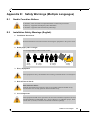
Prior to the installation, please review the safety warnings as follows:
• For Nordic Countries Notices, see Section E.1, “Nordic Countries Notices,” on page 59.
• For Safety Warnings in English, see Section E.2, “Installation Safety Warnings
(English),” on page 59.
• For Safety Warnings in Hebrew, see Section E.3, “הנקתהב תוחיטב תורהזא (Hebrew),” on
page 62.
• For Safety Warnings in Chinese, see Section 1 on page 66.
• For Safety Warnings in French, see Section E.5, “Avertissements de sécurité pour
l'installation (French),” on page 71.
• For Safety Warnings in German, Section E.6, “Installation Sicherheitshinweise(Ger-
man),” on page 74.
• For Safety Warnings in Spanish, see Section E.7, “Advertencias de seguridad de insta-
lación (Spanish),” on page 78.
• For Safety Warnings in Russian, see Section E.8, “Предупреждения по технике
безопасности при установке (Russian),” on page 82.
• For Safety Warnings in Romanian, see Section E.9, “Avertismente privind siguranţa la
instalare (Romanian),” on page 85.
• For Safety Warnings in Croatian, see Section E.10, “Sigurnosna upozorenja za instali-
ranje (Croatian),” on page 89.
• For Safety Warnings in Italian, see Section E.11, “Avvertenze di sicurezza per
l’installazione (Italian),” on page 93.
• For Safety Warnings in Turkish see Section E.12, “Montaj Güvenlik Uyarıları (Turk-
ish),” on page 97.
2.2 System Installation and Initialization
Installation and initialization of the system require attention to the normal mechanical, power,
and thermal precautions for rack-mounted equipment.
The installation procedure for the system involves the following phases:
1. Follow the safety warnings in Section 2.1.
2. Pay attention to the air flow consideration within the system and rack - refer to “Air Flow” on
page 11.
3. Make sure that none of the package contents is missing or damaged - see “Package Contents”
on page 12.
The rack mounting holes conform to the EIA-310 standard for 19-inch racks. Take
precautions to guarantee proper ventilation in order to maintain good airflow at ambi
-
ent temperature.

Installation Rev 1.6
Mellanox Technologies
11
4. Mount the system into a rack enclosure - see “Mounting Options” on page 12.
5. Power on the system - refer to “Initial Power On” on page 29.
6. Perform system bring-up - see “System Bring-Up” on page 30.
7. [Optional]: FRU replacements are described in Section 2.10 on page 34.
2.3 Air Flow
Mellanox systems are offered with two air flow patterns:
• Power (rear) side inlet to connector side outlet - marked with blue power supplies/fans-
FRUs’ handles, as shown in Figure 4.
• Connector (front) side inlet to power side outlet - marked with red power supplies/fans
FRUs’ handles, as shown in
Figure 5.
Table 6 provides an air flow color legend and respective OPN designation
All servers and systems in the same rack should be planned with the same airflow
direction.
All FRU components need to have the same air flow direction. A mismatch in the air
flow will affect the heat dissipation.
Table 6 - Air Flow Color Legend
Direction
OPN
Designation
Description
Ending with
“-R”
Connector side inlet to power side outlet.
Red latches are placed on the power inlet
side.
Ending with
“-F”
Power side inlet to connector side outlet.
Blue latches are placed on the power inlet
side.

Installation
Rev 1.6
Mellanox Technologies
12
Figure 4: Air Flow Direction Marking - Power Side Inlet to Connector Side Outlet
Figure 5: Air Flow Direction Marking - Connector Side Inlet to Power Side Outlet
2.4 Package Contents
Before installing your new system, unpack it and check against the parts list below that all the
parts have been sent. Check the parts for visible damage that may have occurred during shipping.
The SX1710 package content is as follows:
• 1 – System
• 1 – Rail kit
• 1 – Power cable for each power supply unit – Type C13-C14
• 1 – RS232 CABLE - DB9 TO RJ45 HARNESS 2M
•Quick Start Guide
The SX1410 package content is as follows:
• 1 – System
• 1 – Rail kit
• 1 – Power cable for each power supply unit – Type C13-C14
• 1 – Cable retainer for each power supply unit
• 1 – RS232 CABLE - DB9 TO RJ45 HARNESS 2M
•Quick Start Guide
2.5 Mounting Options
By default, the system is sold with the static rail kit described in Section 2.5.1. For SX1410 sys-
tems, this rail kit can be installed in short racks (17"-24") only. For installation in deep racks, a
telescopic rail kit must be used. Such a rail kit can be purchased separately. For the telescopic rail
kit installation instructions, see
Section 2.5.2.
If anything is damaged or missing, contact your sales representative at support@mella-
nox.com.

Installation Rev 1.6
Mellanox Technologies
13
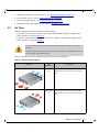
2.5.1 Static Rail Kit
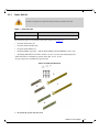
The following parts are included in the static rail kit (see Figure 6):
• 2x Rack mount rails (A)
• 2x Rack mount brackets (B)
• 2x Rack mount blades (C)
• 8x M6 Standard cage nuts¹ ² and 8x M6 Standard pan-head Phillips screws¹ (D)
• 4x Phillips100 DEG F.H TYPE-I ST.ST 6-32 X 1/4 screw with around patch (E)
¹ Other threads are available by special order: M5, 10-32, 12-24
² G-type cage-nut is available by special order.
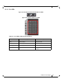
Figure 6: Rack Rail Kit Parts
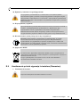
To mount the system into the rack:
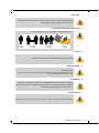
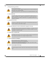
At least two people are required to safely mount the system in the rack.
Table 7 - Installation Kit
Kit OPN Rack Size and Rack Depth Range
MTEF-KIT-A Short (17”-24”) or Standard (24”-34”)

Installation
Rev 1.6
Mellanox Technologies
14
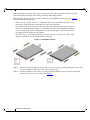
Before mounting the system to the rack, select the way you wish to place the system. Pay atten-
tion to the airflow within the rack cooling, connector and cabling options.
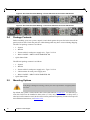
While planning how to place the system, consider the two installation options shown in Figure 7,
and review the following points:
• Make sure the system air flow is compatible with your installation selection. It is
important to keep the airflow within the rack in the same direction.
• Note that the part of the system to which you choose to attach the rails (the front panel
direction, as demonstrated in Option 1 or the FRUs direction, as demonstrated in Option
2) will determine the system’s adjustable side. The system’s part to which the brackets
are attached will be adjacent to the cabinet.
• The FRU side is extractable. Mounting the rack brackets inverted to the FRU side
(Option 2) will allow you to slide the FRUs, in and out.
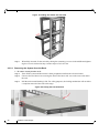
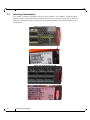
Figure 7: Installation Options
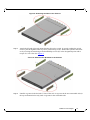
Step 1. Attach the left and right rack mount rails (A) to the switch, by gently pushing the switch chas-
sis’ pins through the slider key holes, until locking occurs.
Step 2. Secure the chassis in the rails by screwing 2 flat head Phillips screws (E) in the designated
points with a torque of 1.5±0.2 Nm. See
Figure 8.

Installation Rev 1.6
Mellanox Technologies
15
Figure 8: Attaching the Rails to the Chassis
Step 3. Attach the left and right rack mount brackets (B) to the switch, by gently pushing the switch
chassis’ pins through the slider key holes, until locking occurs. Secure the system in the brack
-
ets by screwing the remaining 2 flat head Phillips screws (E) in the designated points with a
torque of 1.5±0.2 Nm. See
Figure 9.
Figure 9: Attaching the Brackets to the Chassis
Step 4. Install 8 cage nuts in the desired 1U slots of the rack: 4 cage nuts in the non-extractable side (in
the top and bottom holes only) and 4 cage nuts in the extractable side.

Installation
Rev 1.6
Mellanox Technologies
16
Figure 10: Installing the Cage Nuts
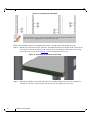
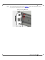
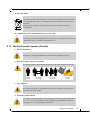
While your installation partner is supporting the system’s weight, perform the following steps:
Step 5. Mount the system into the rack enclosure, and attach the brackets installed on the system to the
rack’s posts. Secure the brackets to the rack’s posts by inserting four M6 screws in the desig
-
nated cage nuts, as described in Figure 11. Do not tighten the screws yet.
Figure 11: Attaching the Brackets to the Rack
Step 6. Slide the two blades into the left and right rails, and adjust them to fit your rack's depth. Use
four M6 screws (D) to fix the blades into the rack. Do not tighten the screws yet.
While each rack U (unit) consists of three holes, the cage nut should be installed verti-
cally with its ears engaging the top and bottom holes only.
Pagina se încarcă...
Pagina se încarcă...
Pagina se încarcă...
Pagina se încarcă...
Pagina se încarcă...
Pagina se încarcă...
Pagina se încarcă...
Pagina se încarcă...
Pagina se încarcă...
Pagina se încarcă...
Pagina se încarcă...
Pagina se încarcă...
Pagina se încarcă...
Pagina se încarcă...
Pagina se încarcă...
Pagina se încarcă...
Pagina se încarcă...
Pagina se încarcă...
Pagina se încarcă...
Pagina se încarcă...
Pagina se încarcă...
Pagina se încarcă...
Pagina se încarcă...
Pagina se încarcă...
Pagina se încarcă...
Pagina se încarcă...
Pagina se încarcă...
Pagina se încarcă...
Pagina se încarcă...
Pagina se încarcă...
Pagina se încarcă...
Pagina se încarcă...
Pagina se încarcă...
Pagina se încarcă...
Pagina se încarcă...
Pagina se încarcă...
Pagina se încarcă...
Pagina se încarcă...
Pagina se încarcă...
Pagina se încarcă...
Pagina se încarcă...
Pagina se încarcă...
Pagina se încarcă...
Pagina se încarcă...
Pagina se încarcă...
Pagina se încarcă...
Pagina se încarcă...
Pagina se încarcă...
Pagina se încarcă...
Pagina se încarcă...
Pagina se încarcă...
Pagina se încarcă...
Pagina se încarcă...
Pagina se încarcă...
Pagina se încarcă...
Pagina se încarcă...
Pagina se încarcă...
Pagina se încarcă...
Pagina se încarcă...
Pagina se încarcă...
Pagina se încarcă...
Pagina se încarcă...
Pagina se încarcă...
Pagina se încarcă...
Pagina se încarcă...
Pagina se încarcă...
Pagina se încarcă...
Pagina se încarcă...
Pagina se încarcă...
Pagina se încarcă...
Pagina se încarcă...
Pagina se încarcă...
Pagina se încarcă...
Pagina se încarcă...
Pagina se încarcă...
Pagina se încarcă...
Pagina se încarcă...
Pagina se încarcă...
Pagina se încarcă...
Pagina se încarcă...
Pagina se încarcă...
Pagina se încarcă...
Pagina se încarcă...
-
 1
1
-
 2
2
-
 3
3
-
 4
4
-
 5
5
-
 6
6
-
 7
7
-
 8
8
-
 9
9
-
 10
10
-
 11
11
-
 12
12
-
 13
13
-
 14
14
-
 15
15
-
 16
16
-
 17
17
-
 18
18
-
 19
19
-
 20
20
-
 21
21
-
 22
22
-
 23
23
-
 24
24
-
 25
25
-
 26
26
-
 27
27
-
 28
28
-
 29
29
-
 30
30
-
 31
31
-
 32
32
-
 33
33
-
 34
34
-
 35
35
-
 36
36
-
 37
37
-
 38
38
-
 39
39
-
 40
40
-
 41
41
-
 42
42
-
 43
43
-
 44
44
-
 45
45
-
 46
46
-
 47
47
-
 48
48
-
 49
49
-
 50
50
-
 51
51
-
 52
52
-
 53
53
-
 54
54
-
 55
55
-
 56
56
-
 57
57
-
 58
58
-
 59
59
-
 60
60
-
 61
61
-
 62
62
-
 63
63
-
 64
64
-
 65
65
-
 66
66
-
 67
67
-
 68
68
-
 69
69
-
 70
70
-
 71
71
-
 72
72
-
 73
73
-
 74
74
-
 75
75
-
 76
76
-
 77
77
-
 78
78
-
 79
79
-
 80
80
-
 81
81
-
 82
82
-
 83
83
-
 84
84
-
 85
85
-
 86
86
-
 87
87
-
 88
88
-
 89
89
-
 90
90
-
 91
91
-
 92
92
-
 93
93
-
 94
94
-
 95
95
-
 96
96
-
 97
97
-
 98
98
-
 99
99
-
 100
100
-
 101
101
-
 102
102
-
 103
103


Mellanox Technologies SX1410 Manual de utilizare
- Tip
- Manual de utilizare
- Acest manual este potrivit și pentru
în alte limbi
Lucrări înrudite
-
Mellanox Technologies SX6710 Hardware User Manual
-
-
-
Mellanox Technologies SX6025 Manual de utilizare
-
-
-
Mellanox Technologies MSX6036G-2SRS Manual de utilizare
-
Alte documente
-
 KYLAND Technology SICOM3000 Hardware Installation Manual
-
LG PCS200R Manual de utilizare
-
DeLOCK 86430 Fișa cu date
-
-
DeLOCK 86432 Fișa cu date
-
Eaton SG48-RC-LCD-55 Mounting And Operating Instructions
-
Cisco Systems MDS 9500 Manual de utilizare
-
SonicWALL TZ270 Instrucțiuni de utilizare
-
CAMPAGNOLA 0310.0420 MASTER Ghid de inițiere rapidă
