Makita UX01G Manual de utilizare
- Categorie
- Unelte electrice
- Tip
- Manual de utilizare

UX01G
EN Cordless Multi Function
Power Head INSTRUCTION MANUAL 6
PL
Bezprzewodowa
Wielofunkcyjna Jednostka
Napędowa INSTRUKCJA OBSŁUGI 17
HU Vezeték nélküli többfunkciós
alapgép HASZNÁLATI KÉZIKÖNYV 29
SK Akumulátorová multifunkčná
motorová jednotka NÁVOD NA OBSLUHU 41
CS Akumulátorová multifunkční
motorová jednotka NÁVOD K OBSLUZE 53
UK
Акумуляторний
багатофункціональний
приводний інструмент
ІНСТРУКЦІЯ З
ЕКСПЛУАТАЦІЇ 64
RO Cap cu motor universal fără
cablu MANUAL DE INSTRUCŢIUNI 77
DE Multifunktions-Antrieb BETRIEBSANLEITUNG 90

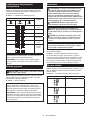
Fig.1
Fig.2
12
1
2
3
4
5
11
10
9
8
Fig.3
2
1
7
3
6
4
5
8
10
911
12
Fig.4
2

2
1
3
Fig.5
1
Fig.6
1
2
Fig.7
1
Fig.8
2
1
Fig.9
2
1
Fig.10
2
1
Fig.11
1
1
2
3
4
5
Fig.12
3

1
2
Fig.13
1
Fig.14
1
2
3
Fig.15
1
Fig.16
Fig.12
3
1
2
Fig.17
1
2
Fig.18
1
2
3
2
Fig.19
Fig.20
4

1
Fig.21
1
2
Fig.22
1
Fig.23
5

6ENGLISH
ENGLISH (Original instructions)
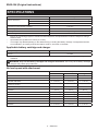
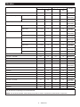
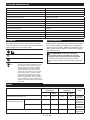
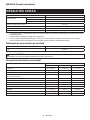
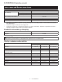
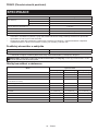
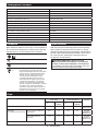
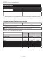
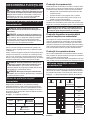
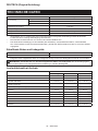
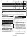
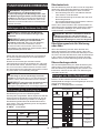
SPECIFICATIONS
Model: UX01G
No load speed
(without attachment)
Low 0 - 5,700 min-1
Medium 0 - 8,200 min-1
High 0 - 9,700 min-1
Overall length (without battery cartridge) 1,001 mm
Rated voltage D.C. 36 V - 40 V max
Net weight 5.3 kg - 11.6 kg
Protection degree IPX4
• Duetoourcontinuingprogramofresearchanddevelopment,thespecicationshereinaresubjecttochange
without notice.
• Specicationsmaydierfromcountrytocountry.
• Theweightmaydierdependingontheattachment(s),includingthebatterycartridge.Thelightestandheavi-
est combination, according to EPTA-Procedure 01/2014, are shown in the table.
Applicable battery cartridge and charger
Battery cartridge BL4020 / BL4025 / BL4040
Charger DC40RA
• Some of the battery cartridges and chargers listed above may not be available depending on your region of
residence.
WARNING: Only use the battery cartridges and chargers listed above. Use of any other battery cartridges
andchargersmaycauseinjuryand/orre.
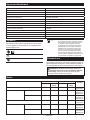
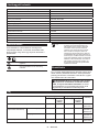
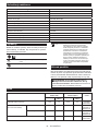
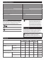
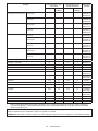
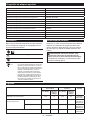
No load speed with attachment
Model Rotation speed
Low Medium High
EM401MP 0 - 4,200 min-1 0 - 6,000 min-1 0 - 7,100 min-1
EM404MP, EM406MP 0 - 3,500 min-1 0 - 5,000 min-1 0 - 6,000 min-1
EM408MP, EM409MP 0 - 4,200 min-1 0 - 6,000 min-1 0 - 7,100 min-1
EN401MP, EN410MP, EN420MP
(Strokes per minute)
0 - 2,400 min-1 0 - 3,400 min-1 0 - 4,000 min-1
EY401MP (chain speed) 0 - 12 m/s 0 - 17 m/s 0 - 20 m/s
KR400MP 0 - 160 min-1 0 - 230 min-1 0 - 280 min-1
KR401MP 0 - 130 min-1 0 - 190 min-1 0 - 230 min-1
EE400MP 0 - 2,800 min-1 0 - 4,000 min-1 0 - 4,700 min-1
EJ400MP 0 - 1,600 min-1 0 - 2,300 min-1 0 - 2,800 min-1
BR400MP 0 - 130 min-1 0 - 190 min-1 0 - 230 min-1
SW400MP 0 - 130 min-1 0 - 190 min-1 0 - 230 min-1
UB400MP 0 - 5,700 min-1 0 - 7,850 min-1 0 - 9,100 min-1

7ENGLISH
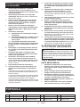
Approved attachment
Type Model
Brushcutter attachment EM401MP, EM404MP
String trimmer attachment EM406MP
Grass trimmer attachment EM408MP, EM409MP
Hedge trimmer attachment EN401MP, EN410MP
Ground trimmer attachment EN420MP
Pole saw attachment EY401MP
Cultivator attachment KR400MP, KR401MP
Edger attachment EE400MP
Coeeharvesterattachment EJ400MP
Shaft extension attachment LE400MP
Power brush attachment BR400MP
Power sweep attachment SW400MP
Blower attachment UB400MP
Symbols
The followings show the symbols which may be used
for the equipment. Be sure that you understand their
meaning before use.
Read instruction manual.
Take particular care and attention.
Do not expose to moisture.
Ni-MH
Li-ion
Only for EU countries
Do not dispose of electric equipment or battery
pack together with household waste material!
In observance of the European Directives,
on Waste Electric and Electronic Equipment
and Batteries and Accumulators and Waste
Batteries and Accumulators and their imple-
mentation in accordance with national laws,
electric equipment and batteries and battery
pack(s) that have reached the end of their life
must be collected separately and returned to an
environmentally compatible recycling facility.
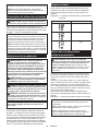
Intended use
This cordless multi function power head is intended for driving an
approved attachment listed in the section "SPECIFICATIONS" of
this instruction manual. Never use the unit for the other purpose.
WARNING: Read the instruction manual of
the attachment as well as this instruction manual
before using. Failure to follow the warnings and
instructionsmayresultseriousinjury.
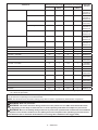
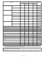
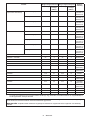
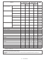
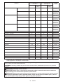
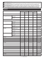
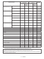
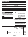
Noise
Attachment
Sound pressure level average
Sound power level average
Applicable
standard
LPA (dB (A))
Uncertainty K
(dB (A))
LWA (dB (A))
Uncertainty K
(dB (A))
EM401MP (as a brushcutter) 79.8 1.2 94.8 2.5
ISO22868
(ISO11806-1)
EM401MP (as a string trimmer)
Nylon cutting head 80.1 1.0 94.3 2.0
ISO22868
(ISO11806-1)/
EN50636-2-91
Plastic blade 79.4 1.0 91.4 2.1
ISO22868
(ISO11806-1)/
EN50636-2-91
EM404MP (as a brushcutter) 79.4 1.4 92.0 1.0
ISO22868
(ISO11806-1)
EM404MP (as a string trimmer)
Nylon cutting head 80.7 1.3 91.9 1.4
ISO22868
(ISO11806-1)/
EN50636-2-91
Plastic blade 78.6 0.7 87.8 0.4
ISO22868
(ISO11806-1)/
EN50636-2-91

8ENGLISH
Attachment
Sound pressure level average
Sound power level average
Applicable
standard
LPA (dB (A))
Uncertainty K
(dB (A))
LWA (dB (A))
Uncertainty K
(dB (A))
EM406MP Nylon cutting head 81.3 0.6 93.4 2.1
ISO22868
(ISO11806-1)/
EN50636-2-91
Plastic blade 78.8 0.4 87.9 0.6
ISO22868
(ISO11806-1)/
EN50636-2-91
EM408MP Metal blade 80.7 1.7 94.7 3.0
ISO22868
(ISO11806-1)
Nylon cutting head 79.5 1.3 92.8 2.7
ISO22868
(ISO11806-1)/
EN50636-2-91
Plastic blade 80.5 1.1 92.2 2.8
ISO22868
(ISO11806-1)/
EN50636-2-91
EM409MP Nylon cutting head 80.6 1.2 93.4 2.3
ISO22868
(ISO11806-1)/
EN50636-2-91
Plastic blade 81.0 1.4 91.9 2.4
ISO22868
(ISO11806-1)/
EN50636-2-91
EN401MP 84 395 3
EN62841-4-2
EN401MP + LE400MP 85 396 3
EN62841-4-2
EN410MP 80 391 3
EN62841-4-2
EN410MP + LE400MP 80 391 3
EN62841-4-2
EN420MP 83 394 3
EN62841-4-2
EY401MP 94 3103 3
ISO22868
(ISO11680-1)
EY401MP + LE400MP 85 3103 3
ISO22868
(ISO11680-1)
KR400MP 77.8 0.7 86.6 1.2 EN709
KR401MP 77.7 0.3 86.7 2.0 EN709
EE400MP 76.1 1.7 88.2 2.3 ISO11789 /
2000/14/EC
EJ400MP 82.9 0.6 94.4 1.5
ISO22868
(ISO11806-1)
EJ400MP + LE400MP 79.7 1.4 94.0 0.7
ISO22868
(ISO11806-1)
BR400MP 80.2 1.0 88.9 0.8
EN60335-2-72
SW400MP 80.3 0.2 88.3 0.6
EN60335-2-72
UB400MP 92.1 1.6 104.1 1.3
EN50636-2-100
• Even if the sound pressure level listed above is 80 dB (A) or less, the level under working may exceed 80 dB
(A). Wear ear protection.
NOTE: The declared noise emission value(s) has been measured in accordance with a standard test method and
may be used for comparing one tool with another.
NOTE: The declared noise emission value(s) may also be used in a preliminary assessment of exposure.
WARNING: Wear ear protection.
WARNING: The noise emission during actual use of the power tool can dier from the declared val-
ue(s) depending on the ways in which the tool is used especially what kind of workpiece is processed.
WARNING: Be sure to identify safety measures to protect the operator that are based on an estimation
of exposure in the actual conditions of use (taking account of all parts of the operating cycle such as the
times when the tool is switched o and when it is running idle in addition to the trigger time).

9ENGLISH
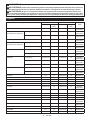
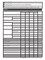
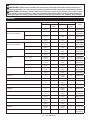
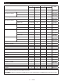
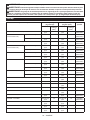
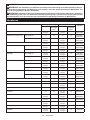
Vibration
Attachment Left handle (Front grip) Right handle (Rear grip) Applicable
standard
ah (m/s2)
Uncertainty K
(m/s2)
ah (m/s2)
Uncertainty K
(m/s2)
EM401MP (as a brushcutter) 2.5 or less 1.5 2.5 or less 1.5
ISO22867
(ISO11806-1)
EM401MP (as a string trimmer)
Nylon cutting head 3.7 1.5 3.0 1.5
ISO22867
(ISO11806-1)
Plastic blade 2.5 or less 1.5 2.5 or less 1.5
ISO22867
(ISO11806-1)
EM404MP (as a brushcutter) 2.5 or less 1.5 2.5 or less 1.5
ISO22867
(ISO11806-1)
EM404MP (as a string trimmer)
Nylon cutting head 2.5 or less 1.5 2.5 or less 1.5
ISO22867
(ISO11806-1)
Plastic blade 2.5 or less 1.5 2.5 or less 1.5
ISO22867
(ISO11806-1)
EM406MP Nylon cutting head 2.5 or less 1.5 2.5 or less 1.5
ISO22867
(ISO11806-1)
Plastic blade 2.5 or less 1.5 2.5 or less 1.5
ISO22867
(ISO11806-1)
EM408MP Metal blade 2.5 or less 1.5 2.5 or less 1.5
ISO22867
(ISO11806-1)
Nylon cutting head 2.5 or less 1.5 2.5 or less 1.5
ISO22867
(ISO11806-1)
Plastic blade 2.5 or less 1.5 2.5 or less 1.5
ISO22867
(ISO11806-1)
EM409MP Nylon cutting head 2.5 or less 1.5 2.5 or less 1.5
ISO22867
(ISO11806-1)
Plastic blade 2.5 or less 1.5 2.5 or less 1.5
ISO22867
(ISO11806-1)
EN401MP 3.4 1.5 2.5 or less 1.5
EN62841-4-2
EN401MP + LE400MP 5.4 1.5 2.7 1.5
EN62841-4-2
EN410MP 2.8 1.5 2.5 or less 1.5
EN62841-4-2
EN410MP + LE400MP 4.4 1.5 2.5 or less 1.5
EN62841-4-2
EN420MP 2.9 1.5 2.5 or less 1.5
EN62841-4-2
EY401MP 2.5 or less 1.5 2.5 or less 1.5
ISO22867
(ISO11680-1)
EY401MP + LE400MP 2.5 or less 1.5 2.5 or less 1.5
ISO22867
(ISO11680-1)
KR400MP 2.5 or less 1.5 2.5 or less 1.5 EN709
KR401MP 2.5 or less 1.5 2.5 or less 1.5 EN709
EE400MP 2.5 or less 1.5 2.5 or less 1.5 ISO11789
EJ400MP 3.5 1.5 3.9 1.5
ISO22867
(ISO11806-1)
EJ400MP + LE400MP 4.8 1.5 2.6 1.5
ISO22867
(ISO11806-1)
BR400MP 2.5 or less 1.5 2.5 or less 1.5
EN60335-2-72
SW400MP 2.5 1.5 2.5 or less 1.5
EN60335-2-72
UB400MP 4.6 1.5 2.5 or less 2.5
EN50636-2-100
NOTE: The declared vibration total value(s) has been measured in accordance with a standard test method and
may be used for comparing one tool with another.
NOTE: The declared vibration total value(s) may also be used in a preliminary assessment of exposure.

10 ENGLISH
WARNING: The vibration emission during actual use of the power tool can dier from the declared
value(s) depending on the ways in which the tool is used especially what kind of workpiece is processed.
WARNING: Be sure to identify safety measures to protect the operator that are based on an estimation
of exposure in the actual conditions of use (taking account of all parts of the operating cycle such as the
times when the tool is switched o and when it is running idle in addition to the trigger time).
EC Declaration of Conformity
For European countries only
The EC declaration of conformity is included as Annex A
to this instruction manual.
SAFETY WARNINGS
General power tool safety warnings
WARNING: Read all safety warnings, instruc-
tions, illustrations and specications provided
with this power tool. Failure to follow all instructions
listedbelowmayresultinelectricshock,reand/or
seriousinjury.
Save all warnings and instruc-
tions for future reference.
The term "power tool" in the warnings refers to your
mains-operated (corded) power tool or battery-operated
(cordless) power tool.
Additional safety instructions
Personal protective equipment
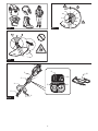
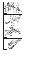
►Fig.1
1. Wear safety helmet, protective goggles and
protective gloves to protect yourself from
ying debris or falling objects.
2. Wear ear protection such as ear mus to pre-
vent hearing loss.
3.
Wear proper clothing and shoes for safe operation,
such as a work overall and sturdy, non-slip shoes.
Do not wear loose clothing or jewelry. Loose clothes,
jewelryorlonghaircanbecaughtinmovingparts.
4.
When touching the cutting blade, wear protective
gloves. Cutting blades can cut bare hands severely.
Work area safety
1. Before operation, examine the work area for
stones or other solid objects. They can be
thrown or cause dangerous kickback and result in
seriousinjuryand/orpropertydamage.
Electrical and battery safety
1. Avoid dangerous environment. Don't use the
tool in dump or wet locations or expose it to
rain. Water entering the tool will increase the risk
of electric shock.
2. Do not dispose of the battery(ies) in a re.
The cell may explode. Check with local codes for
possible special disposal instructions.
3. Do not open or mutilate the battery(ies).
Released electrolyte is corrosive and may cause
damage to the eyes or skin. It may be toxic if
swallowed.
4.
Do not charge battery in rain, or in wet locations.
5. Do not replace the battery with wet hands.
6. Do not replace the battery in the rain.
7. Do not wet the terminal of battery with liquid
such as water, or submerge the battery. Do not
leave the battery in the rain, nor charge, use,
or store the battery in a damp or wet place. If
the terminal gets wet or liquid enters inside of bat-
tery, the battery may be short circuited and there is
ariskofoverheat,re,orexplosion.
8. After removing the battery from the tool or
charger, be sure to attach the battery cover to
the battery and store it in a dry place.
9. If the battery cartridge gets wet, drain the
water inside and then wipe it with a dry cloth.
Dry the battery cartridge completely in a dry
place before use.
Putting into operation
1. The cutting tool has to be equipped with the
guard. Never run the tool with damaged guards
or without guards in place!
2. Make sure there are no electrical cables, water
pipes, gas pipes etc. that could cause a hazard
if damaged by use of the tool.
Operation
1. Always keep your hands, face, and clothes
away from the cutting tool when it is rotating.
Failuretodosomaycausepersonalinjury.
2. During operation, keep bystanders or animals
at least 15 m away from the tool. Stop the tool
as soon as someone approaches.
3. During operation, never stand on an unstable
or slippery surface or a steep slope. During
the cold season, beware of ice and snow and
always ensure secure footing.
4.
Never work on a ladder or tree to avoid loss of control.
5. When you leave the tool, even if it is a short
time, always remove the battery cartridge. The
unattended tool with the battery cartridge installed
may be used by unauthorized person and cause
serious accident.
6. Before starting the tool, be sure that the cut-
ting tool is not touching the ground and other
obstacles such as a tree.
7. Check the cutting attachment frequently
during operation for cracks or damages.
Before the inspection, remove the battery
cartridge and wait until the cutting attachment
stops completely. Replace damaged cutting
attachment immediately, even if it has only
supercial cracks.

11 ENGLISH
8. Do not operate the tool in bad weather or if
there is a risk of lightning.
9. During operation always hold the tool with
both hands. Never hold the tool with one hand
during use.
10. During operation, use the shoulder harness.
Keep the tool on your right side rmly.
11.
Do not touch the gear case during and immedi-
ately after the operation. The gear case becomes
hotduringoperationandcancauseburninjury.
12. Take a rest to prevent loss of control caused
by fatigue. We recommend taking a 10 to 20-min-
ute rest every hour.
13. When you use the tool on muddy ground, wet
slope, or slippery place, pay attention to your
footing.
14. Avoid working in poor environment where
increased user fatigue is expected.
15. Do not use the tool in bad weather where visi-
bility is limited. Failure to do so may cause fall or
incorrect operation due to low visibility.
16. Do not submerge the tool into a puddle.
17. Do not leave the tool unattended outdoors in
the rain.
18. When wet leaves or dirt adhere to the suc-
tion mouth (ventilation window) due to rain,
remove them.
19. Do not use the tool in the snow.
Cutting tools
1. When using cutting blades, avoid kickback
and always prepare for an accidental kickback.
See the section for Kickback.
2. When not in use, attach the blade cover onto
the blade. Remove the cover before operation.
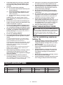
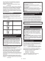
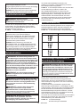
Kickback (Blade thrust)
1. Kickback (blade thrust) is a sudden reaction
to a caught or bound cutting blade. Once it
occurs, the tool is thrown sideway or toward
the operator at great force and it may cause
serious injury.
2. Kickback occurs particularly when applying
the blade segment between 12 and 2 o'clock
to solids, bushes and trees with 3 cm or larger
diameter.
►Fig.2
3. To avoid kickback:
1. Apply the segment between 8 and 11
o'clock.
2. Never apply the segment between 12 and
2 o'clock.
3.
Never apply the segment between 11 and 12
o'clock and between 2 and 5 o'clock, unless
the operator is well trained and experienced
and does it at his/her own risk.
4. Never use cutting blades close to solids,
such as fences, walls, tree trunks and
stones.
5. Never use cutting blades vertically, for
such operations as edging and trimming
hedges.
►Fig.3
Vibration
1. People with poor circulation who are exposed
to excessive vibration may experience injury
to blood vessels or the nervous system.
Vibration may cause the following symptoms
tooccurinthengers,handsorwrists:"Falling
asleep" (numbness), tingling, pain, stabbing sen-
sation, alteration of skin color or of the skin. If any
of these symptoms occur, see a physician!
2. To reduce the risk of "white nger disease",
keep your hands warm during operation and
well maintain the tool and accessories.
Transport
1. Before transporting the tool, turn it o and
remove the battery cartridge. Attach the cover
to the cutting blade.
Maintenance
1. Before doing any maintenance or repair work
or cleaning the tool, always turn it o and
remove the battery cartridge.
2. When handling a cutter blade, always wear
gloves and put the blade cover on the blade.
3. Keep handles dry, clean and free from oil and
grease. Keep all cooling air inlets clear of
debris.
4. Do not wash the tool with high pressure water.
5. When washing the tool, do not let water enter
the electrical mechanism such as battery,
motor, and terminals.
6. Perform inspection or maintenance in a place
where rain can be avoided.
7. After using the tool, remove the adhered dirt
and dry the tool completely before storing.
Depending on the season or the area, there is a
risk of malfunction due to freezing.
Storage
1. Before storing the tool, perform full cleaning
and maintenance. Remove the battery car-
tridge. Attach the cover to the cutting blade.
2. Store the tool in a dry and high or locked loca-
tion out of reach of children.
3. When storing the tool, avoid direct sunlight
and rain, and store it in a place where it does
not get hot or humid.
Important safety instructions for
battery cartridge
1. Before using battery cartridge, read all instruc-
tions and cautionary markings on (1) battery
charger, (2) battery, and (3) product using
battery.
2. Do not disassemble or tamper the battery
cartridge.Itmayresultinare,excessiveheat,
or explosion.
3. If operating time has become excessively
shorter, stop operating immediately. It may
result in a risk of overheating, possible burns
and even an explosion.

12 ENGLISH
4. If electrolyte gets into your eyes, rinse them
out with clear water and seek medical atten-
tion right away. It may result in loss of your
eyesight.
5. Do not short the battery cartridge:
(1) Do not touch the terminals with any con-
ductive material.
(2) Avoid storing battery cartridge in a con-
tainer with other metal objects such as
nails, coins, etc.
(3) Do not expose battery cartridge to water
or rain.
A battery short can cause a large current
ow, overheating, possible burns and even a
breakdown.
6. Do not store and use the tool and battery car-
tridge in locations where the temperature may
reach or exceed 50 °C (122 °F).
7. Do not incinerate the battery cartridge even if
it is severely damaged or is completely worn
out. The battery cartridge can explode in a re.
8. Do not nail, cut, crush, throw, drop the battery
cartridge, or hit against a hard object to the
battery cartridge. Such conduct may result in a
re,excessiveheat,orexplosion.
9. Do not use a damaged battery.
10. The contained lithium-ion batteries are subject
to the Dangerous Goods Legislation require-
ments.
For commercial transports e.g. by third parties,
forwarding agents, special requirement on pack-
aging and labeling must be observed.
For preparation of the item being shipped, consult-
ing an expert for hazardous material is required.
Please also observe possibly more detailed
national regulations.
Tapeormaskoopencontactsandpackupthe
battery in such a manner that it cannot move
around in the packaging.
11. When disposing the battery cartridge, remove
it from the tool and dispose of it in a safe
place. Follow your local regulations relating to
disposal of battery.
12. Use the batteries only with the products
specied by Makita. Installing the batteries to
non-compliantproductsmayresultinare,exces-
sive heat, explosion, or leak of electrolyte.
13. If the tool is not used for a long period of time,
the battery must be removed from the tool.
14. During and after use, the battery cartridge may
take on heat which can cause burns or low
temperature burns. Pay attention to the han-
dling of hot battery cartridges.
15. Do not touch the terminal of the tool imme-
diately after use as it may get hot enough to
cause burns.
16. Do not allow chips, dust, or soil stuck into the
terminals, holes, and grooves of the battery
cartridge. It may result in poor performance or
breakdown of the tool or battery cartridge.
17. Unless the tool supports the use near
high-voltage electrical power lines, do not use
the battery cartridge near a high-voltage elec-
trical power lines. It may result in a malfunction
or breakdown of the tool or battery cartridge.
18. Keep the battery away from children.
SAVE THESE INSTRUCTIONS.
CAUTION: Only use genuine Makita batteries.
Use of non-genuine Makita batteries, or batteries that
have been altered, may result in the battery bursting
causingres,personalinjuryanddamage.Itwill
also void the Makita warranty for the Makita tool and
charger.
Tips for maintaining maximum
battery life
1. Charge the battery cartridge before completely
discharged. Always stop tool operation and
charge the battery cartridge when you notice
less tool power.
2. Never recharge a fully charged battery car-
tridge. Overcharging shortens the battery
service life.
3. Charge the battery cartridge with room tem-
perature at 10 °C - 40 °C (50 °F - 104 °F). Let
a hot battery cartridge cool down before
charging it.
4. When not using the battery cartridge, remove
it from the tool or the charger.
5. Charge the battery cartridge if you do not use
it for a long period (more than six months).
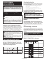
PARTS DESCRIPTION
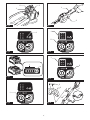
►Fig.4
1Battery cartridge 2Lock-olever 3Hanger 4Handle
5Release button 6Barrier 7Switch trigger 8Speed indicator
9Main power button 10 Caution lamp 11 Reverse button 12 Shoulder harness

13 ENGLISH
FUNCTIONAL
DESCRIPTION
WARNING: Always be sure that the tool is
switched o and the battery cartridge is removed
before adjusting or checking function on the tool.
Failuretoswitchoandremovethebatterycartridge
mayresultinseriouspersonalinjuryfromaccidental
start-up.
Installing or removing battery
cartridge
CAUTION: Always switch o the tool before
installing or removing of the battery cartridge.
CAUTION: Hold the tool and the battery car-
tridge rmly when installing or removing battery
cartridge. Failure to hold the tool and the battery
cartridgermlymaycausethemtoslipoyourhands
and result in damage to the tool and battery cartridge
andapersonalinjury.
►Fig.5: 1. Red indicator 2. Button 3. Battery cartridge
To remove the battery cartridge, slide it from the tool
while sliding the button on the front of the cartridge.
To install the battery cartridge, align the tongue on the
battery cartridge with the groove in the housing and slip
it into place. Insert it all the way until it locks in place
with a little click. If you can see the red indicator on the
upper side of the button, it is not locked completely.
CAUTION: Always install the battery cartridge
fully until the red indicator cannot be seen. If not,
itmayaccidentallyfalloutofthetool,causinginjuryto
you or someone around you.
CAUTION: Do not install the battery cartridge
forcibly. If the cartridge does not slide in easily, it is
not being inserted correctly.
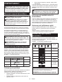
Tool / battery protection system
The tool is equipped with a tool/battery protection
system.Thissystemautomaticallycutsopowerto
the motor to extend tool and battery life. The tool will
automatically stop during operation if the tool is placed
underoneofthefollowingconditions:
►Fig.6: 1. Caution lamp
Caution lamp Status
Color On Blinking
Green Overload
Red (tool) / (battery) Overheat
Red Over
discharge
Overload protection
If the tool or battery gets into one of the following situa-
tion, the tool automatically stops and the caution lamp
startsblinkingingreen:
— The tool is overloaded by entangled weeds or
other debris.
— The cutting tool is locked or kicked back.
— The main power button is turned on while the
switch trigger is being pulled.
In this situation, release the switch trigger and remove
entangled weeds or debris if necessary. After that, pull
the switch trigger again to resume.
CAUTION: If you need to remove the entan-
gled weeds on the tool or release the locked
cutting tool, be sure to turn the tool o before you
start.
Overheat protection for tool or
battery
If the tool or battery cartridge is overheated, the tool
stops automatically. When the tool is overheated, the
caution lamp lights up in red. When the battery cartridge
is overheated, the caution lamp blinks in red. Let the
tool and/or battery cool down before turning the tool on
again.
Overdischarge protection
When the battery capacity becomes low, the tool stops
automatically and the caution lamp starts blinking in red.
If the tool does not operate even when the switches are
operated, remove the battery cartridge from the tool and
charge it.
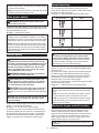
Indicating the remaining battery
capacity
Press the check button on the battery cartridge to indi-
cate the remaining battery capacity. The indicator lamps
light up for a few seconds.
►Fig.7: 1. Indicator lamps 2. Check button
Indicator lamps Remaining
capacity
Lighted O Blinking
75% to 100%
50% to 75%
25% to 50%
0% to 25%
Charge the
battery.
The battery
may have
malfunctioned.

14 ENGLISH
NOTE: Depending on the conditions of use and the
ambienttemperature,theindicationmaydierslightly
from the actual capacity.
NOTE:Therst(farleft)indicatorlampwillblinkwhen
the battery protection system works.
Main power switch
WARNING: Always turn o the main power
switch when not in use.
Press the main power button to turn on the tool. To turn
othetool,pressandholdthemainpowerbuttonuntil
thespeedindicatorsgoo.
►Fig.8: 1. Main power button
NOTE: The caution lamp brinks if the switch trigger
is pulled under unoperatable conditions. The caution
lamp blinks if you turn on the main power switch while
holdingdownthelock-oleverandtheswitchtrigger.
NOTE:Thistoolemploystheautopower-ofunction.
To avoid unintentional start up, the main power switch
will automatically shut down when the switch trigger
is not pulled for a certain period after the main power
switch is turned on.
Switch action
WARNING: For your safety, this tool is
equipped with lock-o lever which prevents the
tool from unintended starting. NEVER use the tool
if it runs when you simply pull the switch trigger
without pressing the lock-o lever. Return the
tool to our authorized service center for proper
repairs BEFORE further usage.
WARNING: NEVER tape down or defeat pur-
pose and function of lock-o lever.
CAUTION: Before installing the battery car-
tridge into the tool, always check to see that the
switch trigger actuates properly and returns to
the "OFF" position when released.
CAUTION: Never put your nger on the main
power button and switch trigger when carrying
the tool. The tool may start unintentionally and cause
injury.
NOTICE: Do not pull the switch trigger hard with-
out pressing the lock-o lever. This can cause
switch breakage.
To prevent the switch trigger from being accidentally
pulled,alock-oleverisprovided.
►Fig.9: 1.Lock-olever2. Switch trigger
To start the tool, turn on the main power switch and
graspthehandle(thelock-oleverisreleasedbythe
grasp) and then pull the switch trigger. Tool speed is
increased by increasing the pressure on the switch
trigger. To stop the tool, release the switch trigger.
Speed adjusting
You can select the tool speed by tapping the main
power button. Each time you tap the main power button,
the level of speed will change.
►Fig.10: 1. Speed indicator 2. Main power button
Speed indicator Mode
High
Medium
Low
Reverse button for debris removal
WARNING: Switch o the tool and remove
the battery cartridge before you remove entan-
gled weeds or debris which the reverse rotation
function can not remove.Failuretoswitchoand
remove the battery cartridge may result in serious
personalinjuryfromaccidentalstart-up.
This tool has a reverse button to change the direction of
rotation. It is only for removing weeds and debris entan-
gled in the tool.
To reverse the rotation, tap the reverse button and pull
theswitchtriggerwhiledepressingthelock-olever
when the cutting tool is stopped. The speed indicators
start blinking, and the cutting tool rotates in reverse
direction when you pull the switch trigger.
To return to regular rotation, release the trigger and wait
until the cutting tool stops.
►Fig.11: 1. Speed indicator 2. Reverse button
NOTE: During the reverse rotation, the tool operates
only for a short period of time and then automatically
stops.
NOTE: Once the tool is stopped, the rotation returns
to regular direction when you start the tool again.
NOTE: If you tap the reverse button while the cutting
tool is still rotating, the tool comes to stop and to be
ready for reverse rotation.
Electronic torque control function
The tool electronically detects a sudden drop in the
rotation speed which may cause a kickback. In this
situation, the tool automatically stops to prevent further
rotation of cutting tool. To restart the tool, release the
switch trigger. Clear the cause of sudden drop in the
rotation speed and then turn the tool on.
NOTE: This function is not a preventive measure for
kickbacks.

15 ENGLISH
ASSEMBLY
WARNING: Always be sure that the tool is
switched o and battery cartridge is removed
before carrying out any work on the tool. Failure to
switchoandremovethebatterycartridgemayresult
inseriouspersonalinjuryfromaccidentalstart-up.
WARNING: Never start the tool unless it is
completely assembled. Operation of the tool in a
partially assembled state may result in serious per-
sonalinjuryfromaccidentalstart-up.
Mounting the handle
Attach the handle with supplied clamps and bolts. Make
sure that the handle is located between the spacer and
the arrow mark. Do not remove or shrink the spacer.
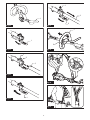
►Fig.12: 1. Clamp 2. Hex socket bolt 3. Handle
4. Arrow mark 5. Spacer
When using the following attachments, be sure to attach
the barrier to the handle using the screw on the barrier.
• Brushcutter attachment *
• Grass trimmer attachment *
• Edger attachment
*. Only when metal blade is attached.
►Fig.13: 1. Barrier 2. Screw
Mounting the attachment pipe
CAUTION: Always check that the attachment
pipe is secured after installation. Improper instal-
lationmaycausetheattachmentfallingofromthe
powerunitandcausepersonalinjury.
Mount the attachment pipe to the power unit.
1. Turn the lever of the power unit toward the attach-
ment side.
►Fig.14: 1. Lever
2. Remove the cap of the attachment. Align the pin
with the arrow mark and insert the attachment pipe until
the release button pops up.
►Fig.15: 1. Release button 2. Arrow mark 3. Pin
3. Turn the lever toward the power unit side.
►Fig.16: 1. Lever
Make sure that the surface of the lever is parallel to the
pipe.
To remove the pipe, turn the lever toward the attach-
ment side and pull the pipe out while pressing down the
release button.
►Fig.17: 1. Release button 2. Lever 3. Pipe
Adjusting the handle position
Adjustthehandlepositiontoobtaincomfortablehan-
dling of the tool.
Loosen the hex socket head bolt on the handle. Move
the handle to a comfortable working position and then
tighten the bolt.
►Fig.18: 1. Handle 2. Hex socket head bolt
Attaching the shoulder harness
WARNING: Be extremely careful to maintain
control of the tool at all times. Do not allow the
tool to be deected toward you or anyone in the
work vicinity. Failure to keep control of the tool
couldresultinseriousinjurytothebystanderandthe
operator.
CAUTION: When you use the tool in combi-
nation of the backpack-type power supply such
as portable power pack, do not use the shoulder
harness included in the tool package, but use the
hanging band recommended by Makita.
If you put on the shoulder harness included in the
tool package and the shoulder harness of the back-
pack-type power supply at the same time, removing
thetoolorbackpack-typepowersupplyisdicultin
case of an emergency, and it may cause an accident
orinjury.Fortherecommendedhangingband,ask
Makita Authorized Service Centers.
CAUTION: Always use the shoulder harness
attached to the tool. Before operation, adjust the
shoulder harness according to the user size to
prevent fatigue.
CAUTION: Before operation, make sure that
the shoulder harness is properly attached to the
tool.
1. Clasp the hook on the shoulder harness to tool's
ring and hanger.
►Fig.19: 1. Ring 2. Hook 3. Hanger
2. Put on the shoulder harness on your left shoulder.
Adjusttheshoulderharnesstoacomfortableworking
position.
►Fig.20
The shoulder harness features a means of quick
release.
Simply squeeze the sides of the buckle to release the
tool from the shoulder harness.
►Fig.21: 1. Buckle
Hex wrench storage
CAUTION: Be careful not to leave the hex
wrench inserted in the tool head. It may cause
injuryand/ordamagetothetool.
When not in use, store the hex wrench as illustrated to
keep it from being lost.
►Fig.22: 1. Handle 2. Hex wrench

16 ENGLISH
MAINTENANCE
WARNING: Always be sure that the tool is
switched o and battery cartridge is removed
before attempting to perform inspection or main-
tenance on the tool.Failuretoswitchoandremove
the battery cartridge may result in serious personal
injuryfromaccidentalstart-up.
NOTICE: Never use gasoline, benzine, thinner,
alcohol or the like. Discoloration, deformation or
cracks may result.
To maintain product SAFETY and RELIABILITY,
repairs,anyothermaintenanceoradjustmentshould
be performed by Makita Authorized or Factory Service
Centers, always using Makita replacement parts.
Cleaning the tool
Cleanthetoolbywipingodust,dirt,orcutograss
with a dry cloth or one dipped in soapy water and wrung
out. To avoid overheating of the tool, be sure to remove
thecutograssordebrisadheredtotheventofthe
tool.
Battery guard
WARNING: Do not remove the battery
guard. Do not use the tool with the battery guard
removed or damaged. Direct impact to the battery
cartridge may cause battery malfunction and result
ininjuryand/orre.Ifthebatteryguardisdeformed
or damaged, contact your authorized service center
for repairs.
►Fig.23: 1. Battery guard
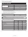
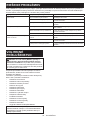
TROUBLESHOOTING
Beforeaskingforrepairs,conductyourowninspectionrst.Ifyoundaproblemthatisnotexplainedinthemanual,
do not attempt to dismantle the tool. Instead, ask Makita Authorized Service Centers, always using Makita replace-
ment parts for repairs.
State of abnormality Probable cause (malfunction) Remedy
Motor does not run. Battery cartridge is not installed. Install the battery cartridge.
Battery problem (under voltage) Rechargethebattery.Ifrechargingisnoteective,
replace battery.
The drive system does not work correctly.
Ask your local authorized service center for repair.
Motor stops running after a little use. Rotation is in reverse.
Change the direction of rotation with the reversing switch.
Battery's charge level is low. Rechargethebattery.Ifrechargingisnoteective,
replace battery.
Overheating. Stop using of tool to allow it to cool down.
It does not reach maximum RPM. Battery is installed improperly.
Install the battery cartridge as described in this manual.
Battery power is dropping. Rechargethebattery.Ifrechargingisnoteective,
replace battery.
The drive system does not work correctly.
Ask your local authorized service center for repair.
OPTIONAL
ACCESSORIES
CAUTION: These accessories or attachments
are recommended for use with your Makita tool
specied in this manual. The use of any other
accessories or attachments might present a risk of
injurytopersons.Onlyuseaccessoryorattachment
for its stated purpose.
If you need any assistance for more details regard-
ing these accessories, ask your local Makita Service
Center.
Refer to "Approved attachment" section for the applica-
ble models for this tool.
• Brushcutter attachment
• String trimmer attachment
• Grass trimmer attachment
• Hedge trimmer attachment
• Ground trimmer attachment
• Pole saw attachment
• Cultivator attachment
• Edger attachment
• Coeeharvesterattachment
• Shaft extension attachment
• Power brush attachment
• Power sweep attachment
• Blower attachment
• Makita genuine battery and charger
NOTE: Some items in the list may be included in the
tool package as standard accessories. They may
dierfromcountrytocountry.

17 POLSKI
POLSKI (Instrukcja oryginalna)
DANE TECHNICZNE
Model: UX01G
Prędkośćbezobciążenia
(bezprzyrządu)
Niska 0–5 700 min-1
Średnia 0–8 200 min-1
Wysoka 0–9 700 min-1
Całkowitadługość(bezakumulatora) 1 001 mm
Napięcieznamionowe Prądstały36V–40Vmaks.
Masa netto 5,3 kg–11,6 kg
Stopieńochrony IPX4
• Wzwiązkuzestaleprowadzonymprzeznasząrmęprogramembadawczo-rozwojowymniniejszedanemogą
uleczmianombezwcześniejszegopowiadomienia.
• Danetechnicznemogąróżnićsięwzależnościodkraju.
• Masamożebyćróżnawzależnościodosprzętu,wtymakumulatora.Wtabeliprzedstawionajestnajlżejszai
najcięższakonguracja,zgodniezprocedurąEPTA01/2014.
Kompatybilne akumulatory i ładowarki
Akumulator BL4020 / BL4025 / BL4040
Ładowarka DC40RA
• Pewnezwymienionychpowyżejakumulatorówiładowarekmogąbyćniedostępnewregioniezamieszkania
użytkownika.
OSTRZEŻENIE: Należy używać wyłącznie akumulatorów i ładowarek wymienionych powyżej.
Używanieinnychakumulatorówiładowarekmożestwarzaćryzykowystąpieniaobrażeńciałalubpożaru.
Prędkość bez obciążenia z przyrządem
Model Prędkość obrotowa
Niska Średnia Wysoka
EM401MP 0–4 200 min-1 0–6 000 min-1 0–7 100 min-1
EM404MP, EM406MP 0–3 500 min-1 0–5 000 min-1 0–6 000 min-1
EM408MP, EM409MP 0–4 200 min-1 0–6 000 min-1 0–7 100 min-1
EN401MP, EN410MP, EN420MP
(Liczbaoscylacjinaminutę)
0–2 400 min-1 0–3 400 min-1 0–4 000 min-1
EY401MP(prędkośćłańcucha) 0–12 m/s 0–17 m/s 0–20 m/s
KR400MP 0–160 min-1 0–230 min-1 0–280 min-1
KR401MP 0–130 min-1 0–190 min-1 0–230 min-1
EE400MP 0–2 800 min-1 0–4 000 min-1 0–4 700 min-1
EJ400MP 0–1 600 min-1 0–2 300 min-1 0–2 800 min-1
BR400MP 0–130 min-1 0–190 min-1 0–230 min-1
SW400MP 0–130 min-1 0–190 min-1 0–230 min-1
UB400MP 0–5 700 min-1 0–7 850 min-1 0–9 100 min-1

18 POLSKI
Przyrząd zatwierdzony
Typ Model
PrzyrządDoKoszeniaTrawy EM401MP, EM404MP
PrzyrządDoPodkaszania EM406MP
Wykaszarka — Przystawka EM408MP, EM409MP
PrzyrządDoCięciaŻywopłotu EN401MP, EN410MP
Przystawka—NożycedoŻywopłotu EN420MP
PrzyrządDoPodcinaniaGałęzi EY401MP
PrzyrządDoSpulchnianiaGleby KR400MP, KR401MP
Przystawka—Krawędziarka EE400MP
PrzyrządDoZbioruKawy EJ400MP
PrzedłużenieWału LE400MP
Szczotka Obrotowa BR400MP
Zamiatarka SW400MP
Przystawka dmuchawy UB400MP
Symbole
Poniżejpokazanosymbole,jakiemogąbyćzastoso-
wanenaurządzeniu.Przedrozpoczęciemużytkowania
należyzapoznaćsięzichznaczeniem.
Przeczytaćinstrukcjęobsługi.
Zachowaćszczególnąostrożność.
Chronićprzedwilgocią.
Ni-MH
Li-ion
DotyczytylkopaństwUE
Niewyrzucaćurządzeńelektrycznychani
akumulatorówwrazzodpadamizgospo-
darstwadomowego!Zgodniezdyrekty-
wamieuropejskimiwsprawiezużytego
sprzętuelektrycznegoielektronicznego
orazbateriiiakumulatoróworazzużytych
bateriiiakumulatorów,atakżedostoso-
waniemichdoprawakrajowego,zużyte
urządzeniaelektryczne,baterieiakumu-
latorynależyskładowaćosobnoiprzeka-
zywaćdozakładurecyklingudziałającego
zgodniezprzepisamidotyczącymiochrony
środowiska.
Przeznaczenie
BezprzewodowaWielofunkcyjnaJednostkaNapędowa
pełnifunkcjęnapędudlazatwierdzonychprzyrządów,
wymienionychwpunkcie„DANETECHNICZNE”niniej-
szejinstrukcjiobsługi.Nigdynieużywaćtegourządze-
niadoinnychcelów.
OSTRZEŻENIE: Zaleca się przeczyta-
nie instrukcji obsługi przyrządu, jak również
niniejszej instrukcji przed użyciem urządzenia.
Niezastosowaniesiędowspomnianychzasadi
zaleceńmożeprzyczynićsiędopoważnychobrażeń
ciała.
Hałas
Przyrząd Średni poziom ciśnienia
akustycznego Średni poziom mocy
akustycznej
Obowiązująca
norma
LPA (dB (A))
Niepewność K
(dB (A))
LWA (dB (A))
Niepewność K
(dB (A))
EM401MP(jakoKosaSpalinowa) 79,8 1,2 94,8 2,5
ISO22868
(ISO11806-1)
EM401MP
(jakoWykaszarkaSpalinowa)
Żyłkowagłowicatnąca 80,1 1,0 94,3 2,0
ISO22868
(ISO11806-1)/
EN50636-2-91
Nóżztworzywasztucznego 79,4 1,0 91,4 2,1
ISO22868
(ISO11806-1)/
EN50636-2-91
EM404MP(jakoKosaSpalinowa) 79,4 1,4 92,0 1,0
ISO22868
(ISO11806-1)

19 POLSKI
Przyrząd Średni poziom ciśnienia
akustycznego Średni poziom mocy
akustycznej
Obowiązująca
norma
LPA (dB (A))
Niepewność K
(dB (A))
LWA (dB (A))
Niepewność K
(dB (A))
EM404MP
(jakoWykaszarkaSpalinowa)
Żyłkowagłowicatnąca 80,7 1,3 91,9 1,4
ISO22868
(ISO11806-1)/
EN50636-2-91
Nóżztworzywasztucznego 78,6 0,7 87,8 0,4
ISO22868
(ISO11806-1)/
EN50636-2-91
EM406MP Żyłkowagłowicatnąca 81,3 0,6 93,4 2,1
ISO22868
(ISO11806-1)/
EN50636-2-91
Nóżztworzywasztucznego 78,8 0,4 87,9 0,6
ISO22868
(ISO11806-1)/
EN50636-2-91
EM408MP Nóżmetalowy 80,7 1,7 94,7 3,0
ISO22868
(ISO11806-1)
Żyłkowagłowicatnąca 79,5 1,3 92,8 2,7
ISO22868
(ISO11806-1)/
EN50636-2-91
Nóżztworzywasztucznego 80,5 1,1 92,2 2,8
ISO22868
(ISO11806-1)/
EN50636-2-91
EM409MP Żyłkowagłowicatnąca 80,6 1,2 93,4 2,3
ISO22868
(ISO11806-1)/
EN50636-2-91
Nóżztworzywasztucznego 81,0 1,4 91,9 2,4
ISO22868
(ISO11806-1)/
EN50636-2-91
EN401MP 84 395 3
EN62841-4-2
EN401MP + LE400MP 85 396 3
EN62841-4-2
EN410MP 80 391 3
EN62841-4-2
EN410MP + LE400MP 80 391 3
EN62841-4-2
EN420MP 83 394 3
EN62841-4-2
EY401MP 94 3103 3
ISO22868
(ISO11680-1)
EY401MP + LE400MP 85 3103 3
ISO22868
(ISO11680-1)
KR400MP 77,8 0,7 86,6 1,2 EN709
KR401MP 77,7 0,3 86,7 2,0 EN709
EE400MP 76,1 1,7 88,2 2,3 ISO11789 /
2000/14/EC
EJ400MP 82,9 0,6 94,4 1,5
ISO22868
(ISO11806-1)
EJ400MP + LE400MP 79,7 1,4 94,0 0,7
ISO22868
(ISO11806-1)
BR400MP 80,2 1,0 88,9 0,8
EN60335-2-72
SW400MP 80,3 0,2 88,3 0,6
EN60335-2-72
UB400MP 92,1 1,6 104,1 1,3
EN50636-2-100
• Nawetjeślipodanypowyżejpoziomciśnieniaakustycznegowynosi80dB(A)lubmniej,poziomtenpodczas
pracymożeprzekroczyć80dB(A).Nosićochronnikisłuchu.
WSKAZÓWKA:Deklarowanawartośćemisjihałasuzostałazmierzonazgodniezestandardowąmetodątestowąi
możnająwykorzystaćdoporównywanianarzędzi.
WSKAZÓWKA:Deklarowanąwartośćemisjihałasumożnatakżewykorzystaćwewstępnejocenienarażenia.

20 POLSKI
OSTRZEŻENIE: Nosić ochronniki słuchu.
OSTRZEŻENIE:
Poziom hałasu wytwarzanego podczas rzeczywistego użytkowania elektronarzędzia może się różnić od
wartości deklarowanej w zależności od sposobu użytkowania narzędzia, a w szczególności od rodzaju obrabianego elementu.
OSTRZEŻENIE:
W oparciu o szacowane narażenie w rzeczywistych warunkach użytkowania należy okre-
ślić środki bezpieczeństwa w celu zapewnienia ochrony operatora (uwzględniając wszystkie elementy cyklu dzia-
łania, tj. czas, kiedy narzędzie jest wyłączone i kiedy pracuje na biegu jałowym, a także czas, kiedy jest włączone).
Drgania
Przyrząd
Lewy uchwyt (rękojeść przednia)
Prawy uchwyt (rękojeść tylna) Obowiązująca
norma
ah (m/s2)
Niepewność K
(m/s2)
ah (m/s2)
Niepewność K
(m/s2)
EM401MP(jakoKosaSpalinowa) 2,5lubmniej 1,5 2,5lubmniej 1,5
ISO22867
(ISO11806-1)
EM401MP
(jakoWykaszarkaSpalinowa)
Żyłkowagłowicatnąca 3,7 1,5 3,0 1,5
ISO22867
(ISO11806-1)
Nóżztworzywasztucznego 2,5lubmniej 1,5 2,5lubmniej 1,5
ISO22867
(ISO11806-1)
EM404MP(jakoKosaSpalinowa) 2,5lubmniej 1,5 2,5lubmniej 1,5
ISO22867
(ISO11806-1)
EM404MP
(jakoWykaszarkaSpalinowa)
Żyłkowagłowicatnąca 2,5lubmniej 1,5 2,5lubmniej 1,5
ISO22867
(ISO11806-1)
Nóżztworzywasztucznego 2,5lubmniej 1,5 2,5lubmniej 1,5
ISO22867
(ISO11806-1)
EM406MP Żyłkowagłowicatnąca 2,5lubmniej 1,5 2,5lubmniej 1,5
ISO22867
(ISO11806-1)
Nóżztworzywasztucznego 2,5lubmniej 1,5 2,5lubmniej 1,5
ISO22867
(ISO11806-1)
EM408MP Nóżmetalowy 2,5lubmniej 1,5 2,5lubmniej 1,5
ISO22867
(ISO11806-1)
Żyłkowagłowicatnąca 2,5lubmniej 1,5 2,5lubmniej 1,5
ISO22867
(ISO11806-1)
Nóżztworzywasztucznego 2,5lubmniej 1,5 2,5lubmniej 1,5
ISO22867
(ISO11806-1)
EM409MP Żyłkowagłowicatnąca 2,5lubmniej 1,5 2,5lubmniej 1,5
ISO22867
(ISO11806-1)
Nóżztworzywasztucznego 2,5lubmniej 1,5 2,5lubmniej 1,5
ISO22867
(ISO11806-1)
EN401MP 3,4 1,5 2,5lubmniej 1,5
EN62841-4-2
EN401MP + LE400MP 5,4 1,5 2,7 1,5
EN62841-4-2
EN410MP 2,8 1,5 2,5lubmniej 1,5
EN62841-4-2
EN410MP + LE400MP 4,4 1,5 2,5lubmniej 1,5
EN62841-4-2
EN420MP 2,9 1,5 2,5lubmniej 1,5
EN62841-4-2
EY401MP 2,5lubmniej 1,5 2,5lubmniej 1,5
ISO22867
(ISO11680-1)
EY401MP + LE400MP 2,5lubmniej 1,5 2,5lubmniej 1,5
ISO22867
(ISO11680-1)
KR400MP 2,5lubmniej 1,5 2,5lubmniej 1,5 EN709
KR401MP 2,5lubmniej 1,5 2,5lubmniej 1,5 EN709
EE400MP 2,5lubmniej 1,5 2,5lubmniej 1,5 ISO11789
EJ400MP 3,5 1,5 3,9 1,5
ISO22867
(ISO11806-1)
EJ400MP + LE400MP 4,8 1,5 2,6 1,5
ISO22867
(ISO11806-1)
BR400MP 2,5lubmniej 1,5 2,5lubmniej 1,5
EN60335-2-72
SW400MP 2,5 1,5 2,5lubmniej 1,5
EN60335-2-72
UB400MP 4,6 1,5 2,5lubmniej 2,5
EN50636-2-100
Pagina se încarcă...
Pagina se încarcă...
Pagina se încarcă...
Pagina se încarcă...
Pagina se încarcă...
Pagina se încarcă...
Pagina se încarcă...
Pagina se încarcă...
Pagina se încarcă...
Pagina se încarcă...
Pagina se încarcă...
Pagina se încarcă...
Pagina se încarcă...
Pagina se încarcă...
Pagina se încarcă...
Pagina se încarcă...
Pagina se încarcă...
Pagina se încarcă...
Pagina se încarcă...
Pagina se încarcă...
Pagina se încarcă...
Pagina se încarcă...
Pagina se încarcă...
Pagina se încarcă...
Pagina se încarcă...
Pagina se încarcă...
Pagina se încarcă...
Pagina se încarcă...
Pagina se încarcă...
Pagina se încarcă...
Pagina se încarcă...
Pagina se încarcă...
Pagina se încarcă...
Pagina se încarcă...
Pagina se încarcă...
Pagina se încarcă...
Pagina se încarcă...
Pagina se încarcă...
Pagina se încarcă...
Pagina se încarcă...
Pagina se încarcă...
Pagina se încarcă...
Pagina se încarcă...
Pagina se încarcă...
Pagina se încarcă...
Pagina se încarcă...
Pagina se încarcă...
Pagina se încarcă...
Pagina se încarcă...
Pagina se încarcă...
Pagina se încarcă...
Pagina se încarcă...
Pagina se încarcă...
Pagina se încarcă...
Pagina se încarcă...
Pagina se încarcă...
Pagina se încarcă...
Pagina se încarcă...
Pagina se încarcă...
Pagina se încarcă...
Pagina se încarcă...
Pagina se încarcă...
Pagina se încarcă...
Pagina se încarcă...
Pagina se încarcă...
Pagina se încarcă...
Pagina se încarcă...
Pagina se încarcă...
Pagina se încarcă...
Pagina se încarcă...
Pagina se încarcă...
Pagina se încarcă...
Pagina se încarcă...
Pagina se încarcă...
Pagina se încarcă...
Pagina se încarcă...
Pagina se încarcă...
Pagina se încarcă...
Pagina se încarcă...
Pagina se încarcă...
Pagina se încarcă...
Pagina se încarcă...
Pagina se încarcă...
Pagina se încarcă...
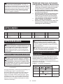
-
 1
1
-
 2
2
-
 3
3
-
 4
4
-
 5
5
-
 6
6
-
 7
7
-
 8
8
-
 9
9
-
 10
10
-
 11
11
-
 12
12
-
 13
13
-
 14
14
-
 15
15
-
 16
16
-
 17
17
-
 18
18
-
 19
19
-
 20
20
-
 21
21
-
 22
22
-
 23
23
-
 24
24
-
 25
25
-
 26
26
-
 27
27
-
 28
28
-
 29
29
-
 30
30
-
 31
31
-
 32
32
-
 33
33
-
 34
34
-
 35
35
-
 36
36
-
 37
37
-
 38
38
-
 39
39
-
 40
40
-
 41
41
-
 42
42
-
 43
43
-
 44
44
-
 45
45
-
 46
46
-
 47
47
-
 48
48
-
 49
49
-
 50
50
-
 51
51
-
 52
52
-
 53
53
-
 54
54
-
 55
55
-
 56
56
-
 57
57
-
 58
58
-
 59
59
-
 60
60
-
 61
61
-
 62
62
-
 63
63
-
 64
64
-
 65
65
-
 66
66
-
 67
67
-
 68
68
-
 69
69
-
 70
70
-
 71
71
-
 72
72
-
 73
73
-
 74
74
-
 75
75
-
 76
76
-
 77
77
-
 78
78
-
 79
79
-
 80
80
-
 81
81
-
 82
82
-
 83
83
-
 84
84
-
 85
85
-
 86
86
-
 87
87
-
 88
88
-
 89
89
-
 90
90
-
 91
91
-
 92
92
-
 93
93
-
 94
94
-
 95
95
-
 96
96
-
 97
97
-
 98
98
-
 99
99
-
 100
100
-
 101
101
-
 102
102
-
 103
103
-
 104
104


Makita UX01G Manual de utilizare
- Categorie
- Unelte electrice
- Tip
- Manual de utilizare
în alte limbi
- slovenčina: Makita UX01G Používateľská príručka
- polski: Makita UX01G Instrukcja obsługi
Lucrări înrudite
-
Makita DUX18 Manual de utilizare
-
Makita DUR192L Manual de utilizare
-
-
-
-
-
-
Makita UR006G Instrucțiuni de utilizare
-
-
Alte documente
-
Dolmar AT-3631 Manual de utilizare
-
-
-
-
Hitachi CG 40EAS P Handling Instructions Manual
-
Ryobi RBC52FSB Manual de utilizare
-
-
-