
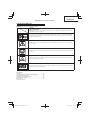
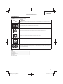
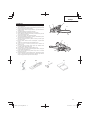
TCS 33EB
Chain Saw
Kettensäge
Αλυσοπρίονο
Piła łańcuchowa
Motorfűrész
Řetězová pila
Elektrikli Testere
Fierastrau cu lant
Motorna verižna žaga
Read through carefully and understand these instructions before use.
Diese Anleitung vor Benutzung des Werkzeugs sorgfältig durchlesen und verstehen.
Διαβάστε προσεκτικά και κατανοήσετε αυτές τις οδηγίες πριν τη χρήση.
Przed użytkowaniem należy dokładnie przeczytać niniejszą instrukcję i zrozumieć jej treść.
Használat előtt olvassa el fi gyelmesen a használati utasítást.
Před použitím si pečlivě přečtěte tento návod a ujistěte se, že mu dobře rozumíte.
Aleti kullanmadan önce bu kılavuzu iyice okuyun ve talimatları anlayın.
Înainte de utilizare, citiţi cu atenţie și înţelegeţi prezentele instrucţiuni.
Pred uporabo natančno preberite in razumite ta navodila.
Handling instructions
Bedienungsanleitung
Οδηγίες χειρισμού
Instrukcja obsługi
Kezelési utasítás
Návod k obsluze
Kullanım talimatları
Instrucţiuni de utilizare
Navodila za rokovanje

2
9
123
456
789
10 11 12
2
1
3
9
11
10
0.5 – 1 mm
6
4
5
8
7
13
12
16
15
14
17

3
13 14 15
16 17 18
19 20 21
22 23 24
19
18
15
20
21
22
23
24
27
25
28
29
26
30

4
0.6 mm
25 26 27
28 29 30
31 32 33
34 35 36
32
31
36
34
35
33
38
37
39
40
42 41
43
44
45 46
47
48
49

5
37 38
39 40
41 42
53
50
51
52
54
54 54
55
56

6
English
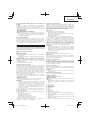
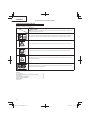
MEANINGS OF SYMBOLS
NOTE: Some units do not carry them.
Symbols
WARNING
The following show symbols used for the machine. Be sure that you understand their meaning before
use.
It is important that you read, fully understand and observe the following safety precautions and warnings.
Careless or improper use of the unit may cause serious or fatal injury.
Read, understand and follow all warnings and instructions in this manual and on the unit.0
Always wear eye, head and ear protectors when using this unit.
Warning, kickback danger. Be careful of possible sudden and accidental upward and/or backward motion
of the guide bar.
One-handed usage not permitted. While cutting, hold saw fi rmly with both hands with thumb fi rmly locked
around front handle.
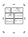
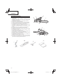
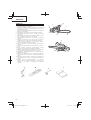
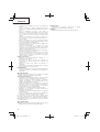
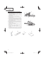
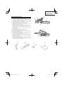
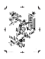
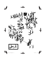
Parts breakdown
(Original instructions)
Contents
WHAT IS WHAT? .............................................................................. 7
WARNINGS AND SAFETY INSTRUCTIONS .................................. 8
SPECIFICATIONS .......................................................................... 10
ASSEMBLY PROCEDURES ........................................................... 11
OPERATING PROCEDURES ......................................................... 11
MAI NT ENA NCE .............................................................................. 13

7
English
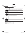
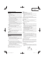
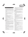
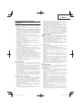
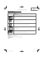
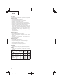
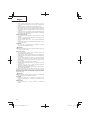
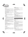
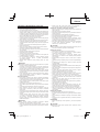
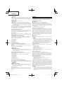
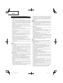
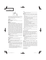
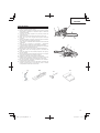
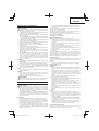
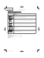
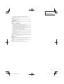
WHAT IS WHAT?
1. Throttle trigger: Device activated by the operatorʼs fi nger, for
controlling the engine speed.
2. Throttle trigger lockout: Device that prevents the accidental
operation of the throttle trigger until manually released.
3. Ignition switch: Device for allowing the engine to be started or
stopped.
4. Oil tank cap: For closing the oil tank.
5. Recoil starter: Pull handle to start the engine.
6. Front handle: Support handle located at or towards the front of
the engine housing.
7. Fuel tank cap: For closing the fuel tank.
8. Choke lever: Device for enriching the fuel/air mixture in the
carburetor, to aid starting.
9. Priming pump: Device for supplying extra fuel, to aid starting.
10. Guide bar: The part that supports and guides the saw chain.
11. Saw chain: Chain, serving as a cutting tool.
12. Chain brake (Front hand guard): Device for stopping or locking
the chain.
13. Spiked bumper (optional): Device for acting as a pivot when in
contact with a tree or log.
14. Chain catcher: device for restraining the saw chain.
15. Guide bar cover: Device for covering the guide bar and saw
chain when the unit is not being used.
16. Combi box spanner: The tool for removing or installing a spark
plug and tensioning the saw chain.
17. Handling instructions: Included with unit. Read before operation
and keep for future reference to learn proper, safe techniques.
13
14
15
15
16
16
17
12
11
10
14
8
2
9
6
5
1
3
7
4

8
English
WARNINGS AND SAFETY INSTRUCTIONS
Operator safety
○ Always wear a safety face shield or goggles.
○ Gloves should be used when sharpening chain.
○ Always wear safety protective equipment such as jacket,
trousers, gloves, helmet, boots with steel toe-caps and non-
slip soles whenever you use a chain saw. For working in trees
the safety boots must be suitable for climbing techniques. Do
not wear loose clothing, jewelry, short pants, sandals or go
barefoot.
Secure hair so it is above shoulder length.
○ Do not operate this tool when you are tired, ill or under the
infl uence of alcohol, drugs or medication.
○ Never let a child or inexperienced person operate the machine.
○ Wear hearing protection. Pay attention to your surroundings.
Be aware of any bystanders who may be signaling a problem.
Remove safety equipment immediately upon shutting off
engine.
○ Wear head protection.
○ Never start or run the engine inside a closed room or building.
Breathing exhaust fumes can kill.
○ For respiratory protection, wear a protection mask while emitting
the chain oil mist and dust from sawdust.
○ Keep handles free of oil and fuel.
○ Keep hands away from cutting equipment.
○ Do not grab or hold the unit by the cutting equipment.
○ When the unit turned off , make sure the cutting attachment has
stopped before the unit is set down.
○ When operation is prolonged, take a break from time to time
so that you may avoid possible Hand-Arm Vibration Syndrome
(HAVS) which is caused by vibration.
○ The operator must obey the local regulations of cutting area.
WARNING
○ Antivibration systems do not guarantee that you will not sustain
Hand-Arm Vibration Syndrome or carpal tunnel syndrome.
Therefore, continual end regular users should monitor closely
the condition of their hands and fi ngers. If any of the above
symptoms appear, seek medical advice immediately.
○ Long or continuous exposure to high noise levels may cause
permanent hearing impairment. Always wear approved hearing
protection when operating a unit/machine.
○ If you are using any medical electric/electronic devices such
as a pacemaker, consult your physician as well as the device
manufacturer prior to operating any power equipment.
Unit/machine safety
○ Inspect the entire unit/machine before each use. Replace
damaged parts. Check for fuel leaks and make sure all fasteners
are in place and securely tightened.
○ Replace parts that are cracked, chipped or damaged in any way
before using the unit/machine.
○ Make sure the side case is properly attached.
○ Keep others away when making carburetor adjustments.
○ Use only accessories as recommended for this unit/machine by
the manufacturer.
○ Never let the chain strike any obstacle. If the chain makes
contact, the machine should be stopped and checked carefully.
○ Make sure the automatic oiler is working. Keep the oil tank fi lled
with clean oil. Never let chain run dry on the bar.
○ All chain saw service, other than the items listed in the operatorʼs/
ownerʼs manual, should be performed by competent chain-saw
service personnel. (For example, if improper tools are used to
remove the fl ywheel or if an improper tool is used to hold the
fl ywheel in order to remove the clutch, structural damage to the
fl ywheel could occur and could subsequently cause the fl ywheel
to burst.)
WARNING
○ Never modify the unit/machine in any way. Do not use your unit/
machine for any job except that for which it is intended.
○ Never use chain saw without any safety equipment or that has
faulty safety equipment. It could result in serious personal
injury.
○ Using guide bar/chain other than recommended by the
manufacturer which are not approved, could result in a high risk
of personal accidents or injury.
Fuel safety
○ Mix and pour fuel outdoors and where there are no sparks or
fl ames.
○ Use a container approved for fuel.
○ Do not smoke or allow smoking near fuel or the unit/machine or
while using the unit/machine.
○ Wipe up all fuel spills before starting engine.
○ Move at least 3 m away from fueling site before starting engine.
○ Stop engine before removing fuel cap.
○ Empty the fuel tank before storing the unit/machine. It is
recommended that the fuel be emptied after each use. If fuel is
left in the tank, store so fuel will not leak.
○ Store unit/machine and fuel in area where fuel vapors cannot
reach sparks or open fl ames from water heaters, electric motors
or switches, furnaces, etc.
WARNING
Fuel is easy to ignite or get explosion or inhale fumes, so that pay
special attention when handling or fi lling fuel.
Cutting safety
○ Do not cut any material other than wood or wooden objects.
○ For respiratory protection, wear an aerosol protection mask
when cutting the wood after insecticide has been applied.
○ Keep others including children, animals, bystanders and helpers
outside the hazard zone. Stop the engine immediately if you are
approached.
○ Hold the unit/machine fi rmly with the right hand on the rear
handle and the left hand on the front handle.
○ Keep fi rm footing and balance. Do not over-reach.
○ Keep all parts of your body away from the muffl er and cutting
attachment when the engine is running.
○ Keep Bar/Chain below waist level.
○ Before felling a tree, the operator must be accustomed to the
sawing techniques of the chain saw.
○ Be sure to pre-plan a safe exit from a failing tree.
○ While cutting, hold saw fi rmly with both hands with thumb fi rmly
locked around front handle, and stand with feet well balanced
and your body balanced.
○ Stand to the side of the saw when cutting - never directly behind
it.
○ Always keep the spiked bumper face to a tree, because the
chain may suddenly be drawn into a tree, if so equipped.
○ When completing a cut, be ready to hold up the units as it breaks
into clear, so it will not follow through and cut your legs, feet or
body, or contact an obstruction.
○ Be alert against kickback (when saw kicks up and back at
operator). Never cut with the nose of the bar.
○ When relocating to a new work area, be sure to shut off the
machine and ensure that all cutting attachments are stopped.
○ Never place the machine on the ground when running.
○ Always ensure that the engine is shut off and any cutting
attachments have completely stopped before clearing debris or
removing grass from the cutting attachment.
○ Always carry a fi rst-aid kit when operating any power
equipment.
○ Never start or run the engine inside a closed room or building
and/or near the infl ammable liquid. Breathing exhaust fumes
can kill.
Maintenance safety
○ Maintain the unit/machine according to recommended
procedures.
○ Disconnect the spark plug before performing maintenance
except for carburetor adjustments.
○ Keep others away when making carburetor adjustments.
○ Use only genuine Tanaka replacement parts as recommended
by the manufacturer.
CAUTION
Do not disassemble the recoil starter. You may get a possibility
of personal injury with recoil spring.

9
English
WARNING
Improper maintenance could result in serious engine damage or
in serious personal injury.
Transpor t and storage
○ Carry the unit/machine by hand with the engine stopped and the
muffl er away from your body.
○ Allow the engine to cool, empty the fuel tank, and secure the
unit/machine before storing or transporting in a vehicle.
○ Empty the fuel tank before storing the unit/machine. It is
recommended that the fuel be emptied after each use. If fuel is
left in the tank, store so fuel will not leak.
○ Store unit/machine out of the reach of children.
○ Clean and maintain the unit carefully and store it in a dry place.
○ Make sure engine switch is off when transporting or storing.
○ When transporting in a vehicle or storage, cover chain with chain
cover.
If situations occur which are not covered in this manual, take care and
use common sense. Contact Tanaka dealer if you need assistance.
Pay special attention to statements preceded by the following words:
WARNING
Indicates a strong possibility of severe personal injury or loss of
life, if instructions are not followed.
CAUTION
Indicates a possibility of personal injury or equipment damage, if
instructions are not followed.
NOTE
Helpful information for correct function and use.

10
English
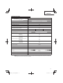
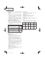
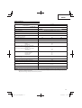
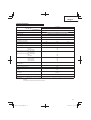
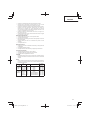
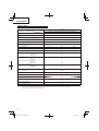
SPECIFICATIONS
Model
TCS33EB
Code “CS” of model name means “Chain saw”
Type of equipment Chain saw, portable
Engine Size (ml) 32.2
Spark Plug NGK BPM-6A or BPMR-6A or equivalent
Fuel Tank Capacity (ml) 350
Chain Oil Tank Capacity (ml) 250
Dry Weight (kg)
(Without guide bar and chain)
3.8
Guide bar length (mm) 300 350 400
Chain pitch (mm) 9.52
Chain gauge (mm) 1.27
Sound pressure level LpA (dB (A)) by ISO 22868
Equivalent
Uncertainty
102
1.0
Sound power level LwA (dB (A)) by ISO 22868
Measured
Uncertainty
Sound power level LwA (dB (A)) by 2000/14/EC
Measured
Guaranteed
110
3
111.6
113
Vibration level (m/s
2
) by ISO 22867
Front handle
Rear handle
Uncertainty
3.2
4.7
0.8
Max. engine power
by ISO 7293 (kW)
1.2/9500
Max. engine speed (min
-1
)12500
Idle engine speed (min
-1
) 3100
Specifi c fuel consumption (g/kWh) 500
Type of chain
91VG
(Oregon)
Max. chain speed (m/sec) 23.8
Sprocket (number of teeth) 6
NOTE: Equivalent noise level/vibration levels by ISO 22868/22867 are calculated as the time-weighted energy total for noise/vibration levels
under various working conditions with the following time distribution: 1/3 idle, 1/3 full, 1/3 racing speed.
* All data subject to change without notice.

11
English
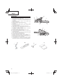
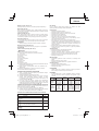
ASSEMBLY PROCEDURES
WARNING
Never try to start engine without side case, bar and chain
securely fastened.
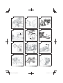
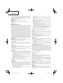
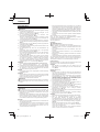
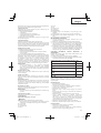
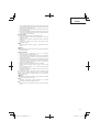
1. Pull the chain brake (14) toward the front handle to check that the
brake is disengaged. (Fig. 9)
2. Remove chain bar clamp nuts (1). Remove the side case (2).
(Fig. 1)
* In case of installing the spiked bumper (3), install the spiked
bumper (3) (if so equipped) to the unit with two screws. (Fig. 2)
3. Install the chain bar (4) onto the bolts (5), then push it toward the
sprocket (6) as far as it will go. (Fig. 3)
4. Confi rm the direction of saw chain (9) is correct as in the fi gure,
and align the chain on the sprocket. (Fig. 4)
5. Guide the chain drive links into the bar groove all around the bar.
6. Install the side case (2) onto the bolts (5).
Make sure that the boss of chain tension adjust bolt (7) fi ts into
the hole of the bar (8). (Fig. 3)
Then tighten the clamp nuts (1) by hand that allows the chain bar
end to move up and down easily. (Fig. 1)
7. Raise the bar end, and tighten the chain (9) by turning the tension
adjustment bolt (10) clockwise. To check proper tension, lightly
lift up the center of chain and there should be about 0.5 – 1.0 mm
clearance between bar and edge of drive link (11). (Fig. 5, 6)
CAUTION
PROPER TENSION IS EXTREMELY IMPORTANT
8. Raise the bar end and securely tighten the chain bar clamp nuts
with the combi box spanner. (Fig. 6)
9. A new chain will stretch so adjust the chain after a few cuts and
watch chain tension carefully for the fi rst half hour of cutting.
NOTE
Check the chain tension frequently for optimum performance
and durability.
CAUTION
○ When the chain is excessively tightened, the bar and chain will
be damaged rapidly. Conversely, when the chain is excessively
loosened, it may get out of the groove in the bar.
○ Always wear gloves when touching the chain.
WARNING
During operation, hold chain saw fi rmly with both hands. A single
hand operation may cause serious injury.
OPERATING PROCEDURES
Fuel (Fig. 7)
WARNING
○ The chain saw is equipped with a two-stroke engine. Always
run the engine on fuel, which is mixed with oil. Provide good
ventilation, when fueling or handling fuel.
○ Fuel contains highly fl ammable and it is possible to get the
serious personal injury when inhaling or spilling on your body.
Always pay attention when handling fuel. Always have good
ventilation when handling fuel inside building.
Fuel
○ Always use branded 89 octane unleaded gasoline.
○ Use genuine two-cycle oil or use a mix between 25:1 to 50:1,
please consult the oil bottle for the ratio or Tanaka dealer.
○ If genuine oil is not available, use an anti-oxidant added quality
oil expressly labeled for air-cooled 2-cycle engine use (JASO
FC GRADE OIL or ISO EGC GRADE). Do not use BIA or TCW
(2-stroke water-cooling type) mixed oil.
○ Never use multi-grade oil (10 W/30) or waste oil.
○ Always mix fuel and oil in a separate clean container.
Always start by fi lling half the amount of gasoline, which is to be
used.
Then add the whole amount of oil. Mix (shake) the fuel mixture. Add
the remaining amount of gasoline.
Mix (shake) the fuel-mix thoroughly before fi lling the fuel tank.
Fueling
WARNING (Fig. 8)
○ Always shut off the engine before refueling.
○ Slowly open the fuel tank (12), when fi lling up with fuel, so that
possible overpressure disappears.
○ Tighten the fuel cap carefully, after fueling.
○ Always move the unit at least 3 m from the fueling area before
starting.
○ Always wash any spilled fuel from clothing immediately with
soap.
○ Be sure to check any fuel leaking after refueling.
Before fueling, clean the tank cap area carefully, to ensure that no
dirt falls into the tank. Make sure that the fuel is well mixed by shaking
the container, before fueling.
Chain oil (Fig. 8)
Fill up with chain oil (13). Always use good quality chain oil. When the
engine is running, the chain oil is automatically discharged.
NOTE
When pouring fuel (12) or chain oil (13) into the tank, place the
unit with cap side up. (Fig. 8)
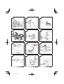
Starting (Fig. 9 - 13)
CAUTION
Before starting, push the chain brake (14) so that the brake is
engaged, and make sure that the bar/chain does not touch
anything.
Pull the choke lever (16) fully, and with the throttle trigger lockout
(18) pressed, pull the throttle trigger (19). If the choke lever (16)
automatically returns to former position, the choke lever (16) is
the auto return choke lever. (Fig. 9, 11, 13)
1. Set ignition switch (15) to ON position. (Fig. 10)
2. Pull the choke lever (16) fully.
The auto return choke lever, if so equipped, will automatically
lock the throttle in starting position. (Fig. 11)
*Push priming pump (17) several times so that fuel fl ows through
bulb into carburetor. (Fig. 11)
3. Pull recoil starter briskly, taking care to keep the handle in your
grasp and not allowing it to snap back. (Fig. 12)
4. When you hear fi rst ignition, push the choke lever (16) fully. (Fig.
11)
5. Pull recoil starter briskly again in the aforementioned manner.
(Fig. 12)
NOTE
If engine does not start, repeat procedures from 2 to 5.
6. If the auto return choke lever is equipped, as soon as engine
starts, with the throttle trigger lockout (18) pressed, pull the
throttle trigger (19) and immediately release the throttle trigger
(19). Then half-throttle is disengaged. (Fig.
13)
Pull the chain brake (14) so that the brake is disengaged. (Fig. 9)
Allow the engine about 2–3 minutes to warm up before subjecting
it to any load.
Do not run the engine at high speed without the load to avoid
shortening the life of the engine.
Chain brake operation (Fig. 9)
Chain brake (14) is designed to activate in an emergency such as
kick-back action. Please check to verify that it works properly before
use.
Application of brake is made by moving the front guard towards the
bar. During the chain brake operation, even if the throttle lever is
pulled, the engine speed does not increase and the chain does not
turn. To release the brake, pull up the chain brake lever.
How to confi rm:
1) Turn off the engine.
2) Holding the chain saw horizontally, release your hand from the
front handle, hit the tip of the guide bar to a stump or a piece
of wood, and confi rm brake operation. Operating level varies by
bar size.

12
English
In case the brake is not eff ective, ask our dealer for inspection and
repairs. If the engine keeps rotating at high speed with the brake
engaged, the clutch will overheat causing trouble.
When the brake engages during operation, immediately release the
throttle lever to stop the engine.
WARNING
Do not carry the machine with the engine running.
Stopping (Fig. 14)
Decrease engine speed, and push ignition switch (15) to stop
position.
WARNING
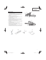
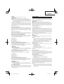
KICKBACK DANGER (Fig. 15)
One of the most severe dangers when working with a chain saw is
the possibility of kickback. Kickback may occur when the upper tip
of the guide bar touches an object, or when the wood closes in and
pinches the saw chain in the cut. Tip contact in some cases may
cause a lightning fast reverse reaction, kicking the guide bar up and
back toward you. Pinching the saw chain along the top of the guide
bar may also push the guide bar rapidly back towards you. Either of
these reactions may cause you to lose control of the saw which could
result in serious personal injury. Even though your saw has safety
built into its design, you should not rely on these safety features
exclusively. Know where your bar tip is at all times. Kickback does
occur if you allow the kickback zone (20) of the bar to touch an object.
Do not use that area. Kickback from pinching is caused by a cut
closing and pinching the upper side of the guide bar. Study your cut
and make sure it will open as you cut through. Maintain control when
the engine is running by always keeping a fi rm grip on the saw with
your right hand on the rear handle, your left hand on the front handle
and your thumbs and fi ngers encircling the handles. Always hold the
saw with both hands during operation and cut at high engine speed.
WARNING
○ Do not overreach or cut above shoulder height.
○ Use extra caution when felling, and do not use the saw in a nose-
high position or above shoulder height.
CHAIN CATCHER
The chain catcher is located on the power head just below the chain
to further prevent the possibility of a broken chain striking the chain
saw user.
WARNING
Do not stand in-line with chain when cutting.
BASIC TECHNIQUES FOR MAKING FELLING, LIMBING AND
BUCKING CUTS
The intention of the following information is to provide you with the
general introduction to wood cutting techniques.
WARNING
○ This information does not cover all specifi c situations, which
may depend on diff erences in terrain, vegetation, kind of wood,
form and size of trees, etc. Consult your servicing dealer,
forestry agent or local forestry schools for advice on specifi c
woodcutting problems in your area. This will make your work
more effi cient and safer.
○ Avoid cutting in adverse weather conditions, such as dense fog,
heavy rain, bitter cold, high winds, etc.
Adverse weather is often tiring to work in and creates potentially
dangerous conditions such as slippery ground.
High winds may force the tree to fall in an unexpected direction
causing property damage or personal injury.
CAUTION
Never use a chain saw to pry or for any purpose for which it is not
intended.
WARNING
○ Avoid stumbling on obstacles such as stumps, roots, rocks,
branches and fallen trees. Watch out for holes and ditches. Be
extremely cautious when working on slopes or uneven ground.
Shut off the saw when moving from one work place to another.
Always cut at wide open throttle. A slow moving chain can easily
catch and force the saw to jerk.
○ Never use the saw with only one hand.
You cannot control the saw properly and you may lose control
and injure yourself severely.
Keep the saw body close to your body to improve control and
reduce strain.
When cutting with the bottom part of the chain the reactive
force will pull the saw away from you towards the wood you are
cutting.
The saw will control the feeding speed and sawdust will be
directed towards you. (Fig. 16)
○ When cutting with the upper part of the chain the reactive force
will push the saw towards you and away from the wood you are
cutting. (Fig. 17)
○ There is a risk of kickback if the saw is pushed far enough so that
you begin to cut with the nose of the bar.
The safest cutting method is to cut with the bottom part of the
chain. Sawing with the upper part makes it much more diffi cult to
control the saw and increases the risk of kickback.
○ In case the chain locked, immediately release the throttle lever.
If the throttle lever keeps rotating at high speed with the chain
locked, the clutch will overheat causing trouble.
NOTE
Always keep the spiked bumper face to a tree, because the
chain may suddenly be drawn into a tree.
FELLING
Felling is more than cutting down a tree. You must also bring it down
as near to an intended place as possible without damaging the tree
or anything else.
Before felling a tree, carefully consider all conditions which may
eff ect the intended direction, such as:
Angle of the tree. Shape of the crown. Snow load on the crown.
Wind conditions. Obstacles within tree range (e.g., other trees,
power lines, roads, buildings, etc.).
WARNING
○ Always observe the general conditions of the tree. Look for
decay and rot in the trunk which will make it more likely to snap
and start to fall before you expect it.
○ Look for dry branches, which may break and hit you when you
are working.
Always keep animals and people at least twice the tree length
away while felling. Clear away shrubs and branches from around
the tree.
Prepare a path of retreat away from the felling direction.
BASIC RULES FOR FELLING TREES
Normally the felling consists of two main cutting operations, notching
and making the felling cut. Start making the upper notch cut on the
side of the tree facing the feeling direction. Look through the kerf as
you saw the lower cut so you do not saw too deep into the trunk. The
notch should be deep enough to create a hinge of suffi cient width
and strength. The notch opening should be wide enough to direct
the fall of the tree as long as possible. Saw the felling cut from the
other side of the tree between one and two inches (3–5 cm) above
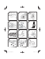
the edge of the notch. (Fig. 18)
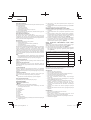
21. Felling direction
22. 45° minimum notch opening
23. Hinge
24. Felling cut
Never saw completely through the trunk. Always leave a hinge.
The hinge guides the tree. If the trunk is completely cut through, you
lose control over the felling direction.
Insert a wedge or a felling lever in the cut well before the tree
becomes unstable and starts to move. This will prevent the guide
bar from binding in the felling cut if you have misjudged the falling
direction. Make sure no people have come into the range of the
falling tree before you push it over.
FELLING CUT, TRUNK DIAMETER MORE THAN TWICE GUIDE
BAR LENGTH
Cut a large, wide notch. Then cut a recess into the center of the notch.
Always leave a hinge on both sides of the center cut. (Fig. 19)
Complete the felling cut by sawing around the trunk as in the
Fig. 20.
WARNING
These methods are extremely dangerous because they involve
the use of the nose of guide bar and can result in kickback.
Only properly trained professionals should attempt these
techniques.

13
English
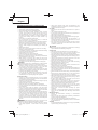
LIMBING
Limbing is removing the branches from a feller tree.
WARNING
A majority of kickback accidents occur during Iimbing.
Do not use the nose of the guide bar. Be extremely cautious and
avoid contacting the log, other limbs or objects with the nose
of the guide bar. Be extremely cautious of limbs under tension.
They can spring back towards you and cause loss of control
resulting in injury. (Fig. 21)
Stand on the left side of the trunk. Maintain a secure footing and
rest the saw on the trunk. Hold the saw close to you so that you are
in full control of it. Keep well away from the chain. Move only when
the trunk is between you and the chain. Watch out for spring back of
limbs under tension.
LIMBING THICK BRANCHES
When limbing thick branches, the guide bar may get pinched easily.
Branches under tension often snap up, so cut troublesome branches
in small steps. Apply the same principles as for cross cutting. Think
ahead and be aware of the possible consequences of all your
actions.
CROSS CUTTING/BUCKING
Before starting to cut through the log, try to imagine what is going to
happen. Look out for stresses in the log and cut through it in such a
manner that the guide bar will not get pinched.
CROSS CUTTING LOGS, PRESSURE ON TOP
Take a fi rm stance. Begin with an upper cut. Do not cut too deeply,
about 1/3 of the log diameter is enough. Finish with a bottom cut.
The saw cuts should meet. (Fig. 22)
25. Relieving cut
26. Cross cut
27. Pressure on top
28. Pressure side
29. Tension side
30. Relative depth of saw cuts
THICK LOG, LARGER THAN GUIDE BAR LENGTH
Begin by cutting on the opposite side of the log. Pull the saw towards
you, followed by previous procedure. (Fig. 23)
If the log is lying on the ground make a boring cut to avoid cutting into
the ground. Finish with a bottom cut. (Fig. 24)
WARNING
KICKBACK DANGER
Do not attempt a boring cut if you are not properly trained. A
boring cut involves the use of the nose of the guide bar and can
result in kickback.
CROSS CUTTING LOGS, PRESSURE ON BOTTOM
Take a fi rm stance. Begin with a bottom cut. The depth of the cut
should be about 1/3 of the log diameter.
Finish with an upper cut. The saw cuts should meet. (Fig. 25)
31. Relieving cut
32. Cross cut
33. Pressure on bottom
34. Tension side
35. Pressure side
36. Relative depth of saw cuts
THICK LOG, LARGER THAN GUIDE BAR LENGTH
Begin by cutting on the opposite side of the log. Pull the saw towards
you, followed by previous procedure. Make a boring cut if the log is
close to the ground. Finish with a top cut. (Fig. 26)
WARNING
KICKBACK DANGER
Do not attempt a boring cut if you are not properly trained. A
boring cut involves the use of the nose of the guide bar and can
result in kickback. (Fig. 27)
IF THE SAW GETS STUCK
Stop the engine. Raise the log or change its position, using a thick
branch or pole as a lever. Do not try to pull the saw free. If you do,
you can deform the handle or be injured by the saw chain if the saw
is suddenly released.
MAINTENANCE
MAINTENANCE, REPLACEMENT OR REPAIR OF THE EMISSION
CONTROL DEVICES AND SYSTEM MAY BE PERFORMED BY ANY
NON-ROAD ENGINE REPAIR ESTABLISHMENT OR INDIVIDUAL.
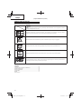
Carburetor adjustment (Fig. 28)
WARNING
Never start the engine without the complete clutch cover.
Otherwise the clutch can come loose and cause personal injuries.
In the carburetor, fuel is mixed with air. When the engine is test run at
the factory, the carburetor is adjusted. A further adjustment may be
required, according to climate and altitude. The carburetor has one
adjustment possibility:
T = Idle speed adjustment screw.
Idle speed adjustment (T)
Check that the air fi lter is clean. When the idle speed is correct, the
cutting attachment will not rotate. If adjustment is required, close
(clockwise) the T-screw, with the engine running, until the cutting
attachment starts to rotate. Open (counter-clockwise) the screw
until the cutting attachment stops. You have reached the correct idle
speed when the engine runs smoothly in all positions well below the
rpm when the cutting attachment starts to rotate.
If the cutting attachment still rotates after idle speed adjustment,
contact Tanaka dealer.
WARNING
When the engine is idling the cutting attachment must under no
circumstances rotate.
NOTE
Some models sold in areas with strict exhaust emission
regulation do not have high and low speed carburetor
adjustments. Such adjustments may allow the engine to be
operated outside of their emission compliance limits. For these
models, the only carburetor adjustment is idle speed.
If you are not familiar with this type of adjustment, please ask for
assistance from your Tanaka dealer.
Air fi lter (Fig. 29)
The air fi lter (37) must be cleaned from dust and dirt in order to avoid:
○ Carburetor malfunctions.
○ Starting problems.
○ Engine power reduction.
○ Unnecessary wear on the engine parts.
○ Abnormal fuel consumption.
Clean the air fi lter daily or more often if working in exceptionally
dusty areas.
Cleaning the air fi lter
Remove the air fi lter cover (38) and the fi lter (37).
Rinse them in warm soap suds. Check that the fi lter is dry before
reassembly. An air fi lter that has been used for some time cannot be
cleaned completely. Therefore, it must regularly be replaced with a
new one. A damaged fi lter must always be replaced.
Spark plug (Fig. 30)
The spark plug condition is infl uenced by:
○ An incorrect carburetor setting.
○ Wrong fuel mixture (too much oil in the gasoline)
○ A dirty air fi lter.
○ Hard running conditions (such as cold weather).
These factors cause deposits on the spark plug electrodes, which
may result in malfunction and starting diffi culties. If the engine is
low on power, diffi cult to start or runs poorly at idling speed, always
check the spark plug fi rst. If the spark plug is dirty, clean it and check
the electrode gap. Readjust if necessary. The correct gap is 0.6 mm.
The spark plug should be replaced after about 100 operation hours
or earlier if the electrodes are badly eroded.
NOTE
In some areas, local law requires using a resistor spark plug
to suppress ignition signals. If this machine was originally
equipped with resistor spark plug, use same type of spark plug
for replacement.

14
English
Oiler port (Fig. 31)
Clean the chain oiler port (39) whenever possible.
Guide bar (Fig. 32)
Before using the machine, clean the groove and oiler port (40) in the
bar with the special gauge off ered as an optional accessory.
Side case (Fig. 33)
Always keep the side case and drive area clean of saw dust and
debris. Periodically apply oil or grease to this area to protect from
corrosion as some trees contain high levels of acid.
Fuel fi lter (Fig. 34)
Remove the fuel fi lter from the fuel tank and thoroughly wash it in
solvent. After that, push the fi lter into the tank completely.
NOTE
If the fi lter is hard due to dust and dirt, replace it.
Chain oil fi lter (Fig. 35)
Remove the oil fi lter and thoroughly wash it in solvent.
CHAIN SHARPENING
Parts of a cutter (Fig. 36, 37)
WARNING
○ Gloves should be used when sharpening chain.
○ Be sure to round off the front edge to reduce the chance of
kickback or tie-strap breakage.
41. Top plate
42. Working corner
43. Side plate
44. Gullet
45. Heel
46. Chassis
47. Rivet hole
48. Toe
49. Depth gauge
50. Correct angle on top plate (degree of angle depends on chain
type)
51. Slightly protruding “hook” or point (curve on non-chisel chain)
52. Top of depth gauge at correct height below top plate
53. Front of depth gauge rounded off
LOWERING DEPTH GAUGES WITH A FILE
1) If you sharpen your cutters with a fi le holder, check and lower the
depth.
2) Check depth gauges every third sharpening.
3) Place depth gauge tool on cutter. If depth gauge projects, fi le
it level with the top of the tool. Always fi le from the inside of the
chain toward an outside cutter. (Fig. 38)
4) Round off front corner to maintain original shape of depth gauge
after using depth gauge tool. Always follow the recommended
depth gauge setting found in the maintenance or operator
manual for your saw. (Fig. 39)
GENERAL INSTRUCTIONS FOR FILING CUTTERS
File (54) cutter on one side of the chain from the inside out. File on
forward stroke only. (Fig. 40)
5) Keep all cutters the same length. (Fig. 41)
6) File enough to remove any damage to cutting edges (side plate
(55) and top plate (56)) of cutter. (Fig. 42)
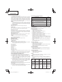
SHARPENING ANGLES FOR SHARPENING SAW CHAIN
1. Part Number 91VG
2. Pitch 3/8″
3. Depth Gauge Setting 0.025″
4. Side Plate Filing Angle 80°
5. Top Plate Angle 30°
6. File Guide Angle 90°
Maintenance schedule
Below you will fi nd some general maintenance instructions. For
further information please contact Tanaka dealer.
Daily maintenance
○ Clean the exterior of the unit.
○ Clean the chain oil fi lter port.
○ Clean the groove and oil fi lter port in the guide bar.
○ Clean the side case of saw dust.
○ Check that the saw chain is sharp.
○ Check that the bar nuts are suffi ciently tightened.
○ Make sure that the chain transport guard is undamaged and that
it can be securely fi tted.
○ Check that nuts and screws are suffi ciently tightened.
Especially inspect the bolt of muffl er and ensure that they are
properly tightened before starting engine. Should any of the
bolts be loose, retighten them immediately. Failure to do so
could result in serious hazard.
○ Check the tip of the bar. Please exchange it for the new one
when it is worn out.
○ Check the band of chain brake. Please exchange it for the new
one when it is worn out.
Weekly maintenance
○ Check the starter, especially cord.
○ Clean the exterior of the spark plug.
○ Remove the spark plug and check the electrode gap. Adjust it to
0.6 mm or change the spark plug.
○ Check that the air intake at the starter is not clogged.
○ Clean the air fi lter.
Monthly maintenance
○ Rinse the fuel tank with gasoline, and clean fuel fi lter.
○ Clean chain oil fi lter.
○ Clean the exterior of the carburetor and the space around it.
Quarterly maintenance
○ Clean the cooling fi ns on the cylinder.
○ Clean the fan and the space around it.
○ Clean the muffl er of carbon.
CAUTION
Cleaning of cylinder fi ns, fan and muffl er shall be done by a
Tanaka Authorized Service Center.
NOTE
When ordering the parts to your nearest dealer, please use the
item numbers showing on the parts breakdown section in this
instruction.
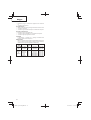
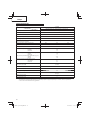
BAR NO.
LENGTH-
TYPE
NOSE-
TYPE
CHAIN
NO.
(OREGON)
MODEL
NO.
E&S
PO12-50CR
PO14-50CR
PO16-50CR
12″
14″
16″
SPROCKET
SPROCKET
SPROCKET
91VG – 045X
91VG – 052X
91VG – 057X
MODEL
NO.
OREGON
120SDEA041
140SDEA041
160SDEA041
26779
26780
160NDEA041
12″
14″
16″
12″
14″
16″
SPROCKET
SPROCKET
SPROCKET
NON-ARMOR
NON-ARMOR
NON-ARMOR
91VG – 045X
91VG – 052X
91VG – 057X
91VG – 045X
91VG – 052X
91VG – 057X

BEDEUTUNGEN DER SYMBOLE
HINWEIS: Nicht alle Geräte sind mit diesen Symbolen versehen.
Symbole
WARNUNG
Die folgenden Symbole werden für diese Maschine verwendet. Achten Sie darauf, diese vor der
Verwendung zu verstehen.
Es ist wichtig, dass Sie sich mit den nachfolgenden Vorsichtsmaßnahmen und Warnungen vertraut
machen und diese befolgen. Unvorsichtige oder unsachgemäße Handhabung des Geräts kann schwere
oder tödliche Verletzungen zur Folge haben.
Lesen, verstehen und befolgen Sie alle Warnungen und Anweisungen in dieser Anleitung und am Gerät
selbst.
Bei Gebrauch des Geräts immer Gesichts-, Kopf- und Gehörschutz tragen.
Vorsicht Rückschlaggefahr! Die Kettensäge kann plötzlich und unvermittelt mit der Führungsschiene
nach oben und/oder nach hinten zurückschlagen.
Nicht einhändig führen! Die Säge bei Schnitten sicher mit beiden Händen halten und den Daumen fest
um den vorderen Griff legen.
Stückliste
(Übersetzung der ursprünglichen Anleitung)
Inhalt
TEILEBEZEICHNUNG EN ............................................................... 16
WARN- UND SICHERHEITSHINWEISE ........................................ 17
TECHNISCHE DATEN .................................................................... 19
ZUSAMMENBAU ............................................................................ 20
BE TRIEB ......................................................................................... 20
WARTU NG ...................................................................................... 2 3
Deutsch
15

TEILEBEZEICHNUNGEN
1. Gashebel: Dieser mit dem Finger betätigte Hebel regelt die
Motordrehzahl.
2. Gashebelsperre: Diese Vorrichtung verhindert bis zur
Entriegelung der Sperre mit der Hand eine unbeabsichtigte
Betätigung des Gashebels.
3. Zündschalter: Ermöglicht Starten und Stoppen des Motors.
4. Öltankdeckel: Verschließt den Öltank.
5. Zugstarter: Der Motor wird durch Ziehen des Griff es gestartet.
6. Vorderer Griff : Der Griff am vorderen Teil des Motorgehäuses.
7. K raftstoff tankdeckel: Verschließt den Kraftstoff tank.
8. Chokehebel: Vorrichtung zum Anreichern des Kraftstoff -Luft-
Gemischs im Vergaser, die den Kaltstart erleichtert.
9. Startpumpe: Starthilfevorrichtung, die die Kraftstoff menge
erhöht.
10. Führungsschiene: Dieses Teil hält und führt die Sägekette.
11. Sägekette: Die als Schneidwerkzeug dienende Kette.
12. Kettenbremse (vorderer Handschutz): Vorrichtung zum Stoppen
bzw. Arretieren der Kette.
13. Krallenanschlag (Sonderzubehör): Eine Vorrichtung, die am
Stamm angesetzt als Drehpunkt dient.
14. Kettenfangbolzen: Vorrichtung zum Auff angen der Kette, wenn
diese reißen oder von der Schiene springen sollte.
15. Kettenschutz: Wird bei Nichtgebrauch zum Schutz über die
Führungsschiene und Kette geschoben.
16. Kombischlüssel: Werkzeug für den Aus- und Einbau der
Zündkerze sowie zum Spannen der Kette.
17. Bedienungsanleitung: Gehört zum Lieferumfang des Geräts.
Sie sollte vor der Inbetriebnahme gelesen und danach zum
späteren Nachschlagen gut aufbewahrt werden.
13
14
15
15
16
16
17
12
11
10
14
8
2
9
6
5
1
3
7
4
Deutsch
16

WARN- UND SICHERHEITSHINWEISE
Bedienersicherheit
○ Immer einen Gesichtsschutz bzw. eine Schutzbrille tragen.
○ Beim Schärfen der Kette Handschuhe tragen.
○ Beim Gebrauch einer Kettensäge immer Schutzbekleidung,
wie Schnittschutzjacke, Gehörschutz, Schnittschutzhose,
Schutzbrille, Schutzhelm sowie Sicherheitsschuhe tragen. Bei
Arbeiten in einem Baum sind für Klettertechniken geeignete
Sicherheitsschuhe zu tragen. Das Arbeiten mit lockerer
Kleidung, Schmuck, kurzen Hosen, Sandalen oder barfuß ist zu
vermeiden.
Das Haar ist so zu sichern, dass es nicht bis zu den Schultern
herunterhängt.
○ Das Ger ät dar f nicht vo n Personen b edie nt werd en, die über müdet
oder krank sind oder unter Alkohol- oder Medikamenteneinfl uss
stehen.
○ Unter keinen Umständen zulassen, dass ein Kind oder eine
unerfahrene Person mit dem Gerät arbeitet.
○ Gehörschutz tragen. Die Umgebung im Auge behalten.
Auf Beistehende achten, die unter Umständen ein Problem
signalisieren.
Die Schutzbekleidung erst nach Abstellen des Motors wieder
ablegen.
○ Kopfschutz tragen.
○ Der Motor darf nie innerhalb geschlossener Räume oder
Gebäude gestartet bzw. betrieben werden.
Einatmen der Abgase kann den Tod zur Folge haben.
○ Eine Atemschutzmaske tragen, um sich gegen den
aufgewirbelten Kettenölnebel und Sägemehlstaub zu schützen.
○ Die Griff e frei von Öl und Kraftstoff halten.
○ Hände weg von den Schneiden!
○ Das Gerät nicht an der Schneidgarnitur fassen bzw. halten.
○ Das Gerät nach dem Ausschalten des Motors erst am
Boden abstellen, wenn das Schneidwerkzeug zum Stillstand
gekommen ist.
○ Bei Dauereinsatz von Zeit zu Zeit eine Pause einlegen als
vorbeugende Maßnahme gegen die Weißfi ngerkrankheit, die
durch ständige Vibration verursacht wird.
○ Der Bediener muss die für den Arbeitsplatz geltenden örtlichen
Vorschriften beachten.
WARNUNG
○ Vibrationsdämpfungssysteme sind kein garantierter Schutz
gegen die Weißfi ngerkrankheit bzw. das Karpaltunnelsyndrom.
Daher ist bei regelmäßigem Dauereinsatz des Geräts der
Zustand von Fingern und Handwurzel gründlich zu überwachen.
Falls Symptome der obengenannten Krankheiten auftreten,
sofort einen Arzt aufsuchen.
○ Das menschliche Gehör kann einen permanenten Schaden
davontragen, wenn es längere Zeit oder andauernd einem
hohen Geräuschpegel ausgesetzt wird. Daher beim Betrieb des
Geräts stets einen vorschriftsmäßigen Gehörschutz tragen.
○ Träger eines medizinischen elektrischen bzw. elektronischen
Geräts (Herzschrittmacher u. dgl.) sollten sich vor dem Gebrauch
eines Motorgeräts von Ihrem Arzt sowie dem Hersteller des
Geräts diesbezüglich beraten lassen.
Geräte-/Maschinensicherheit
○ Das Gerät vor jedem Einsatz einer eingehenden Kontrolle
unterziehen. Beschädigte Teile ersetzen. Das Gerät auf
auslaufenden Kraftstoff untersuchen und sicherstellen, dass
alle Befestigungsteile vorhanden und sicher angezogen sind.
○ Gerissene, ausgebrochene oder auf andere Weise beschädigte
Teile sind vor dem Einsatz des Gerätes durch neue zu ersetzen.
○ Es ist darauf zu achten, dass das Seitengehäuse ordnungsgemäß
angebracht ist.
○ Während der Vergasereinstellung dürfen sich andere Personen
nicht in der Nähe aufhalten.
○ Nur das vom Hersteller für dieses Gerät empfohlene Zubehör
darf verwendet werden.
○ Darauf achten, dass die Kette nirgendwo anschlägt. Sollte die
laufende Kette an einen Gegenstand schlagen, den Motor sofort
stoppen und die Kette prüfen.
○ Sicherstellen, dass die automatische Kettenschmierung
ordnungsgemäß arbeitet. Den Öltank stets mit sauberem
Öl gefüllt halten. Die Kette darf nicht trocken auf der
Führungsschiene laufen!
○ Alle Wartungsarbeiten an der Kettensäge, mit Ausnahme der
in der Betriebs-/Bedienungsanleitung aufgeführten, müssen
durch mit Kettensägen vertraute Fachkräfte durchgeführt
werden. (Wird beispielsweise das Polrad unfachmännisch oder
mit ungeeigneten Werkzeugen ausgebaut oder zum Ausbau der
Kupplung blockiert, kann das Polrad beschädigt werden und als
Folge davon brechen.)
WARNUNG
○ Keinesfalls das Gerät in irgendeiner Weise abändern. Das Gerät
nur für die Zwecke verwenden, für die es bestimmt ist.
○ Niemals eine Kettensäge ohne Sicherheitsvorrichtungen oder
mit einer defekten Sicherheitsvorrichtung verwenden. Dies
kann eine schwere Verletzung nach sich ziehen.
○ Die Verwendung einer nicht vom Hersteller empfohlenen
bzw. zugelassenen Schneidgarnitur erhöht das Unfall- und
Verletzungsrisiko.
Kraftstoff sicherheit
○ Kraftstoff im Freien und von Funken und Feuer entfernt mischen
und einfüllen.
○ Einen für Kraftstoff e zugelassenen Behälter verwenden.
○ In der Nähe des Kraftstoff s, des Geräts sowie beim Arbeiten mit
dem Gerät ist das Rauchen zu unterlassen.
○ Vor dem Starten des Motors muss eventuell verschütteter
Kraftstoff restlos entfernt werden.
○ Zum Starten des Motors das Gerät mindestens 3 m von der
Kraftstoff einfüllstelle entfernen.
○ Vor dem Abnehmen des Tankdeckels den Motor ausschalten.
○ Vor der Einlagerung des Geräts den Kraftstoff tank leeren. Es
wird empfohlen, den Kraftstoff nach jedem Einsatz abzulassen.
Mit gefülltem Tank ist das Gerät so zu lagern, dass kein Kraftstoff
ausläuft.
○ Gerät und Kraftstoff an einem Ort lagern, wo Kraftstoff dämpfe
nicht mit Funken oder off enen Flammen von Wassererhitzern,
Elektromotoren oder elektrischen Schaltern, Öfen usw. in
Berührung kommen können.
WARNUNG
Kraftstoff ist leicht entfl ammbar, kann explodieren und schadet
den Atemwegen, weshalb bei der Handhabung von und der
Befüllung mit Kraftstoff entsprechend umsichtig vorzugehen
ist.
Schneidsicherheit
○ Das Gerät ausschließlich zum Schneiden von Holz und aus Holz
bestehenden Gegenständen verwenden.
○ Zum Schutz der Atmungsorgane beim Schneiden von Holz,
auf dem Insektenvernichtungsmittel versprüht wurde, eine
Aerosolschutzmaske tragen.
○ Kinder, Tiere, Umstehende, Helfer usw. dürfen sich nicht
innerhalb der Gefahrenzone aufhalten. Den Motor sofort
abstellen, wenn sich jemand nähert.
○ Das Gerät mit der rechten Hand am hinteren Griff und der linken
Hand am vorderen Griff fest halten.
○ Auf sicheren Stand und gutes Gleichgewicht achten! Nicht zu
weit vorbeugen.
○ Schneidwerkzeug und Schalldämpfer bei laufendem Motor vom
Körper fernhalten.
○ Die Schneidgarnitur stets unter der Gürtellinie halten.
○ Der Bediener muss sich vor dem Fällen eines Baumes mit der
Handhabung und den Funktionen der Kettensäge vertraut
machen.
○ Vor dem dem Fällen eines Baumes einen sicheren Rückzugsweg
festlegen und freiräumen.
○ Die Kettensäge beim Schneiden mit beiden Händen und um den
vorderen Griff gelegtem Daumen sicher festhalten, dabei einen
festen Stand suchen, der ein sicheres Körpergleichgewicht
gewährleistet.
○ Das Gerät beim Sägen seitlich versetzt halten. Niemals direkt
hinter der Kettensäge stehen!
○ Den Krallenanschlag, sofern vorhanden, stets gegen den Baum
gedrückt halten, da die Säge anderenfalls unerwartet in den
Baum hineingezogen werden kann.
Deutsch
17

○ Das aus einem Schnitt freikommende Gerät gut abstützen,
damit sich die Bewegung nicht zu den Beinen, Füßen oder
einem anderen Gegenstand fortsetzt.
○ Vorsicht Rückschlaggefahr! Niemals mit der Schienenspitze
sägen, da die Kettensäge unvermittelt gegen den Bediener
zurückschlagen kann.
○ Bei Standortwechseln unbedingt den Motor ausschalten und
sicherstellen, dass das Schneidwerkzeug still steht.
○ Das Gerät niemals mit laufendem Motor auf dem Boden
abstellen.
○ Vor dem Entfernen von Schmutz und Spänen vom
Schneidwerkzeug den Motor ausschalten und sicherstellen,
dass die Kette zum Stillstand gekommen ist.
○ Beim Arbeiten mit Motorgeräten stets einen Verbandskasten
mitführen.
○ Der Motor darf nie innerhalb geschlossener Räume oder
Gebäude und/oder in der Nähe entfl ammbarer Flüssigkeiten
gestartet bzw. betrieben werden. Einatmen der Abgase kann
den Tod zur Folge haben.
Wartungssicherheit
○ Das Gerät vorschriftsmäßig warten.
○ Vor Durchführung von Wartungsarbeiten den Zündkerzenstecker
abziehen, sofern es sich nicht um eine Vergasereinstellung
handelt.
○ Während der Vergasereinstellung dürfen sich andere Personen
nicht in der Nähe aufhalten.
○ Nur Original-Ersatzteile von Tanaka verwenden, wie vom
Hersteller empfohlen.
VORSICHT
Den Zugstarter (Anwerfvorrichtung) nicht zerlegen. Die in der
Vorrichtung gespannte Feder kann Verletzungen verursachen.
WARNUNG
Fehlerhafte Wartung kann eine schwere Beschädigung des
Motors oder eine schwere Verletzung zur Folge haben.
Transpor t und Lagerung
○ Das Gerät mit ausgeschaltetem Motor tragen und den
Schalldämpfer vom Körper fernhalten.
○ Den Motor abkühlen lassen, den Kraftstoff tank entleeren und
das Gerät sichern, bevor es gelagert oder in einem Fahrzeug
transportiert wird.
○ Vor der Einlagerung des Geräts den Kraftstoff tank leeren. Es
wird empfohlen, den Kraftstoff nach jedem Einsatz abzulassen.
Mit gefülltem Tank ist das Gerät so zu lagern, dass kein Kraftstoff
ausläuft.
○ Das Gerät so lagern, dass es nicht in Kinderhände gerät.
○ Das Gerät sorgfältig reinigen und warten, um es dann an einem
trockenen Ort zu lagern.
○ Bei Transport oder Lagerung darauf achten, dass der
Zündschalter ausgeschaltet ist.
○ Zum Transportieren in einem Fahrzeug und bei der Lagerung
den Kettenschutz anbringen.
In Situationen, die nicht in dieser Anleitung behandelt sind,
entsprechende Vor- und Umsicht walten lassen. Sollten Sie Hilfe
benötigen, wenden Sie sich an den Tanaka-Fachhändler. Die
folgenden Wörter sind Abschnitten vorangestellt, denen besondere
Aufmerksamkeit gewidmet werden sollte:
WARNUNG
Kennzeichnet Anweisungen, deren Nichtbefolgung eine
schwere Verletzung oder den Tod zur Folge haben kann.
VORSICHT
Kennzeichnet Anweisungen, deren Nichtbefolgung eine
Verletzung oder Sachschaden zur Folge haben kann.
HINWEIS
Ken nze ich net n üt zli ch e Info rm ati one n fü r den vo rs ch rif t smä ßig en
Gebrauch.
Deutsch
18

TECHNISCHE DATEN
Modell
TCS33EB
Der Code “CS” des Modellnamens bedeutet “Kettensäge”
Geräteart Kettensäge, tragbar
Motorgröße (ml) 32,2
Zündkerze NGK BPM-6A oder BPMR-6A oder gleichwertige
Kraftstoff tankvolumen (ml) 350
Kettenöltankvolumen (ml) 250
Trockengewicht (kg)
(Ohne Führungsschiene und Kette)
3,8
Schnittlänge der Führungsschiene (mm)
300 350 400
Kettenteilung (mm) 9,52
Treibgliedstärke (mm) 1,27
Schalldruckpegel LpA (dB (A)) nach ISO 22868
Äquivalen
Unsicherheit
102
1,0
Schallleistungspegel LwA (dB (A)) nach ISO 22868
Gemessener
Unsicherheit
Schallleistungspegel LwA (dB (A)) nach 2000/14/EG
Gemessener
Garantierter
110
3
111,6
113
Vibrationspegel (m/s
2
) nach ISO 22867
Vorderer Griff
Hinterer Griff
Unsicherheit
3,2
4,7
0,8
Max. Motorleistung
nach ISO 7293 (kW)
1,2/9500
Max. Motordrehzahl (min
-1
)12500
Leerlaufdrehzahl (min
-1
) 3100
Spezieller Kraftstoff verbrauch (g/kWh)
500
Kettentyp
91VG
(Oregon)
Max. Kettengeschwindigkeit (m/Sek.)
23,8
Kettenrad (Zähnezahl) 6
HINWEIS: Äquivalente Geräusch-/Vibrationspegel (gemäß ISO 22868/22867) werden als zeitgewichtete Energiesumme für Geräusch-/
Vibrationspegel unter verschiedenen Arbeitsbedingungen mit folgender Zeitaufteilung berechnet: 1/3 Leerlauf, 1/3 Volllast, 1/3
Vollgas.
* Änderungen der technischen Daten jederzeit vorbehalten.
Deutsch
19

ZUSAMMENBAU
WARNUNG
Den Motor niemals starten, ohne dass Seitengehäuse, Stange
und Kette fest angebracht sind.
1. Ziehen Sie die Kettenbremse (14) zum Vordergriff , um zu
überprüfen, ob sie angezogen ist.(Abb. 9)
2. Die Schienenbefestigungsmuttern (1) entfernen. Das
Seitengehäuse (2) abnehmen. (Abb. 1)
* Wenn der Krallenanschlag (3) (sofern vorhanden) montiert
werden soll, den Krallenanschlag (3) mit zwei Schrauben an
der Motoreinheit befestigen. (Abb. 2)
3. Die Führungsschiene (4) auf die Gewindebolzen (5) aufsetzen
und dann bis zum Anschlag in Richtung Kettenrad (6) schieben.
(Abb. 3)
4. Die Sägekette (9) wie in der Abbildung korrekt ausgerichtet um
das Kettenrad legen. (Abb. 4)
5. Die Treibglieder der Kette um die gesamte Schiene herum in die
Führungsnut einpassen.
6. Das Seitengehäuse (2) wieder auf die Gewindebolzen (5)
stecken.
Sicherstellen, dass der Spannschieber (7) in die zugehörige
Bohrung der Schiene (8) greift. (Abb. 3)
Nun die Schienenbefestigungsmuttern (1) von Hand anziehen,
damit sich das Schwertende leicht nach oben und unten
bewegen lässt. (Abb. 1).
7. Das Schienenende anheben und die Kette (9) durch Drehen
der Spannschraube (10) im Uhrzeigersinn spannen. Die Kette
zum Prüfen der Spannung in Schienenmitte leicht anheben:
Die Kette ist richtig gespannt, wenn der Abstand zwischen
der Schienenoberkante und der Lauffl äche des angehobenen
Treibglieds (11) ca. 0,5 – 1,0 mm beträgt. (Abb. 5, 6)
VORSICHT
DIE KETTE MUSS ORDNUNGSGEMÄSS GESPANNT SEIN!
8. Die Schienenbefestigungsmuttern bei angehobenem
Schienenende mit dem Kombischlüssel fest anziehen. (Abb. 6)
9. Eine neue Kette dehnt sich nach der Inbetriebnahme, weshalb
die Spannung in den ersten 30 Betriebsminuten wiederholt
kontrolliert und berichtigt werden muss.
HINWEIS
Für optimale Leistung und Langlebigkeit die Kettenspannung
regelmäßig prüfen.
VORSICHT
○ Wenn die Kette zu stark gespannt ist, erhöht sich der Verschleiß
an Kette und Schiene. Bei zu schwacher Spannung kann die
Kette aus der Führungsnut der Schiene springen.
○ Die Kette nur mit Handschuhen anfassen!
WARNUNG
Die Kettensäge beim Betrieb mit beiden Händen gut festhalten.
Einhändiges Sägen kann eine schwere Verletzung zur Folge
haben!
BETRIEB
Kraftstoff (Abb. 7)
WARNUNG
○ Die Kettensäge ist mit einem Zweitaktmotor ausgestattet. Sie
muss daher mit Kraftstoff -Ölgemisch betrieben werden. Beim
Handhaben von und Auftanken mit Kraftstoff ist stets für gute
Belüftung zu sorgen.
○ Kraftstoff ist stark entfl ammbar und kann bei Einatmen oder
Hautkontakt schwere Verletzungen verursachen. Kraftstoff stets
mit der geboteten Umsicht handhaben. Bei der Handhabung
von Kraftstoff in Gebäuden immer auf gute Belüftung achten.
Kraftstoff
○ Stets einen bleifreien Markenkraftstoff mit einer Oktanzahl von
89 oder höher verwenden.
○ Original-Zweitaktöl oder ein fertiges Zweitaktgemisch in einem
Mischungsverhältnis von 25:1 bis 50:1 verwenden. Hierzu
die Anweisungen am Zweitaktölbehälter beachten oder den
Tanaka-Fachhändler um Rat fragen.
○ Sollte Original-Zweitaktöl nicht zu beschaff en sein, ein qualitativ
hochwertiges Öl mit Korrosionsschutz-Additiv verwenden, das
laut Beschriftung speziell für luftgekühlte Zweitaktmotoren
geeignet ist (Klassifi kation JASO FC oder ISO EGC). Kein BIA-
oder TCW-Mischöl (für wassergekühlte Zweitakter) verwenden.
○ Unter keinen Umständen Mehrbereichsöl (10 W/30) oder Altöl
verwenden.
○ Kraftstoff und Öl immer in einem separaten sauberen Behälter
mischen.
Zuerst die Hälfte des zu verwendenden Benzins einfüllen.
Dann die ganze Ölmenge. Die Kraftstoff mischung verrühren
(schütteln). Das restliche Benzin hinzufügen.
Die Kraftstoff mischung sorgfältig verrühren (schütteln), bevor sie in
den Tank gefüllt wird.
Auftanken
WARNUNG (Abb. 8)
○ Zum Auftanken immer den Motor ausschalten.
○ Zum Auff üllen mit Kraftstoff den den Kraftstoff tankdeckel (12)
langsam aufdrehen, um einen eventuellen Überdruck im Tank
abzulassen.
○ Den Kraftstoff tankdeckel nach dem Auftanken wieder fest
anziehen.
○ Den Motor des Geräts mindestens 3 m von der Auftankstelle
entfernt starten.
○ Eventuell auf die Kleidung geratenen Kraftstoff sofort mit Seife
auswaschen.
○ Nach dem Auftanken sicherstellen, dass kein Kraftstoff ausläuft.
Vor dem Betanken des Geräts den Bereich um den Tankdeckel gut
säubern, damit kein Schmutz in den Tank gerät. Den Behälter vor
dem Betanken schütteln, um Öl und Kraftstoff gut zu mischen.
Kettenöl (Abb. 8)
Mit Kettenöl auff üllen (13). Stets Öl bester Qualität verwenden. Bei
laufendem Motor wird automatisch Kettenöl gefördert.
HINWEIS
Zum Einfüllen von Kraftstoff (12) oder Kettenöl (13) die
Kettensäge so auf die Seite legen, dass die Tankdeckel oben
sind. (Abb. 8)
Starten (Abb. 9 - 13)
VORSICHT
Vor dem Starten des Motors drücken Sie die Kettenbremse
(14), sodass sie angezogen ist und die Schneidgarnitur keinen
anderen Gegenstand berührt.
Den Chokehebel (16) ganz herausziehen und bei gedrückter
Drosselklappensperre (18) den Drosselklappen-Auslöser
(19) ziehen. Wenn der Chokehebel (16) automatisch in seine
vorherige Stellung zurückkehrt, ist der Chokehebel (16) der
Automatik-Chokehebel. (Abb. 9, 11, 13)
1. Den Zündschalter (15) auf ON (Start) stellen. (Abb. 10)
2. Den Chokehebel (16) ganz herausziehen.
Der Automatik-Chokehebel stellt die Drosselklappe, wenn er
eingebaut ist, in der Startposition fest. (Abb. 11)
*Die Ansaugpumpe (17) mehrmals betätigen, damit Kraftstoff
durch die Pumpe in den Vergaser fl ießt. (Abb. 11)
3. Den Griff des Zugstarters gut mit der Hand festhalten, um
Rückschläge zu verhindern, und in kräftiger, schneller
Bewegung ziehen. (Abb.
12)
4. Wenn Sie die erste Zündung hören, drücken Sie den Chokehebel
(16) ganz hinein. (Abb. 11)
5. Danach wieder, wie zuvor beschrieben, in schneller, kräftiger
Bewegung am Zugstarter ziehen. (Abb. 12)
HINWEIS
Sollte der Motor nicht anspringen, Schritte 2 bis 5 wiederholen.
6. Wenn ein Automatik-Chokehebel eingebaut ist, ziehen
Sie gleich beim Anlassen des Motors bei gedrückter
Drosselklappensperre (18) den Drosselklappen-Auslöser (19)
und geben Sie den Drosselklappen-Auslöser (19) wieder frei.
Dadurch wird die halbe Drosselklappenstellung freigegeben.
(Abb. 13)
Ziehen Sie die Kettenbremse (14), um sie zu lösen. (Abb. 9)
Lassen Sie den Motor nach ca. 2 bis 3 Minuten warmlaufen
lassen, bevor er belastet wird.
Lassen Sie den Motor nicht bei hoher Drehzahl unbelastet
laufen, um nicht seine Lebenszeit zu verkürzen.
Deutsch
20
Pagina se încarcă...
Pagina se încarcă...
Pagina se încarcă...
Pagina se încarcă...
Pagina se încarcă...
Pagina se încarcă...
Pagina se încarcă...
Pagina se încarcă...
Pagina se încarcă...
Pagina se încarcă...
Pagina se încarcă...
Pagina se încarcă...
Pagina se încarcă...
Pagina se încarcă...
Pagina se încarcă...
Pagina se încarcă...
Pagina se încarcă...
Pagina se încarcă...
Pagina se încarcă...
Pagina se încarcă...
Pagina se încarcă...
Pagina se încarcă...
Pagina se încarcă...
Pagina se încarcă...
Pagina se încarcă...
Pagina se încarcă...
Pagina se încarcă...
Pagina se încarcă...
Pagina se încarcă...
Pagina se încarcă...
Pagina se încarcă...
Pagina se încarcă...
Pagina se încarcă...
Pagina se încarcă...
Pagina se încarcă...
Pagina se încarcă...
Pagina se încarcă...
Pagina se încarcă...
Pagina se încarcă...
Pagina se încarcă...
Pagina se încarcă...
Pagina se încarcă...
Pagina se încarcă...
Pagina se încarcă...
Pagina se încarcă...
Pagina se încarcă...
Pagina se încarcă...
Pagina se încarcă...
Pagina se încarcă...
Pagina se încarcă...
Pagina se încarcă...
Pagina se încarcă...
Pagina se încarcă...
Pagina se încarcă...
Pagina se încarcă...
Pagina se încarcă...
Pagina se încarcă...
Pagina se încarcă...
Pagina se încarcă...
Pagina se încarcă...
Pagina se încarcă...
Pagina se încarcă...
Pagina se încarcă...
Pagina se încarcă...
Pagina se încarcă...
Pagina se încarcă...
Pagina se încarcă...
Pagina se încarcă...
Pagina se încarcă...
Pagina se încarcă...
Pagina se încarcă...
Pagina se încarcă...
Pagina se încarcă...
Pagina se încarcă...
Pagina se încarcă...
Pagina se încarcă...
-
 1
1
-
 2
2
-
 3
3
-
 4
4
-
 5
5
-
 6
6
-
 7
7
-
 8
8
-
 9
9
-
 10
10
-
 11
11
-
 12
12
-
 13
13
-
 14
14
-
 15
15
-
 16
16
-
 17
17
-
 18
18
-
 19
19
-
 20
20
-
 21
21
-
 22
22
-
 23
23
-
 24
24
-
 25
25
-
 26
26
-
 27
27
-
 28
28
-
 29
29
-
 30
30
-
 31
31
-
 32
32
-
 33
33
-
 34
34
-
 35
35
-
 36
36
-
 37
37
-
 38
38
-
 39
39
-
 40
40
-
 41
41
-
 42
42
-
 43
43
-
 44
44
-
 45
45
-
 46
46
-
 47
47
-
 48
48
-
 49
49
-
 50
50
-
 51
51
-
 52
52
-
 53
53
-
 54
54
-
 55
55
-
 56
56
-
 57
57
-
 58
58
-
 59
59
-
 60
60
-
 61
61
-
 62
62
-
 63
63
-
 64
64
-
 65
65
-
 66
66
-
 67
67
-
 68
68
-
 69
69
-
 70
70
-
 71
71
-
 72
72
-
 73
73
-
 74
74
-
 75
75
-
 76
76
-
 77
77
-
 78
78
-
 79
79
-
 80
80
-
 81
81
-
 82
82
-
 83
83
-
 84
84
-
 85
85
-
 86
86
-
 87
87
-
 88
88
-
 89
89
-
 90
90
-
 91
91
-
 92
92
-
 93
93
-
 94
94
-
 95
95
-
 96
96


Hikoki TCS 33EB Manual de utilizare
- Tip
- Manual de utilizare
- Acest manual este potrivit și pentru
în alte limbi
- Türkçe: Hikoki TCS 33EB Kullanım kılavuzu
- slovenčina: Hikoki TCS 33EB Používateľská príručka
- polski: Hikoki TCS 33EB Instrukcja obsługi
Lucrări înrudite
Alte documente
-
Skil 0780 AT Manual de utilizare
-
Hitachi CS 30Y Handling Instructions Manual
-
Hitachi CS30SB Manualul proprietarului
-
Alpina Garden AC38 Instrucțiuni de utilizare
-
McCulloch Inline 1650 Manual de utilizare
-
Hitachi CS 33EDT Handling Instructions Manual
-
-
-
Ikra PCS 5046 Manualul proprietarului
-
Husqvarna 130 Manual de utilizare