

1
1
A
A
B
288
560
288
509
124
150-250
149
104
269
718
760
600
164
90
124
200
2020
164
‡
3419 2 5
7
8
6
12
11
10
2
4
14
15
16
13
A B
VAM150F 145 97
VAM250F 132 146
2
2
14 2 3
15
7
8
13
6
7
10
8
9
6
42
1211
1
5
1
14
4PEN586307-1_2019_06.book Page 1 Tuesday, July 9, 2019 1:29 PM

Daikin Europe N.V.
CE - DECLARATION-OF-CONFORMITY
CE - KONFORMITÄTSERKLÄRUNG
CE - DECLARATION-DE-CONFORMITE
CE - CONFORMITEITSVERKLARING
CE - DECLARACION-DE-CONFORMIDAD
CE - DICHIARAZIONE-DI-CONFORMITA
CE - ¢H§ø™H ™YMMOPºø™H™
CE - DECLARAÇÃO-DE-CONFORMIDADE
СЕ - ЗАЯВЛЕНИЕ-О-СООТВЕТСТВИИ
CE - OPFYLDELSESERKLÆRING
CE - FÖRSÄKRAN-OM-ÖVERENSTÄMMELSE
CE - ERKLÆRING OM-SAMSVAR
CE - ILMOITUS-YHDENMUKAISUUDESTA
CE -
PROHLÁŠENÍ-O-SHODĚ
CE -
IZJAVA-O-USKLAĐENOSTI
CE - MEGFELELŐSÉGI-NYILATKOZAT
CE -
DEKLARACJA-ZGODNOŚCI
CE -
DECLARAŢIE-DE-CONFORMITATE
CE - I
ZJAVA O SKLADNOSTI
CE -
VASTAVUSDEKLARATSIOON
CE -
ДЕКЛАРАЦИЯ-ЗА-СЪОТВЕТСТВИЕ
CE -
ATITIKTIES-DEKLARACIJA
CE -
ATBILSTĪBAS-DEKLARĀCIJA
CE -
VYHLÁSENIE-ZHODY
CE - UYUMLULUK-BEYANI
01
are in conformity with the following standard(s) or other normative document(s), provided that these are used in accordance with our
instructions:
02
der/den folgenden Norm(en) oder einem anderen Normdokument oder -dokumenten entspricht/entsprechen, unter der Voraussetzung,
daß sie gemäß unseren Anweisungen eingesetzt werden:
03
sont conformes à la/aux norme(s) ou autre(s) document(s) normatif(s), pour autant qu'ils soient utilisés conformément à nos instructions:
04
conform de volgende norm(en) of één of meer andere bindende documenten zijn, op voorwaarde dat ze worden gebruikt overeenkomstig
onze instructies:
05
están en conformidad con la(s) siguiente(s) norma(s) u otro(s) documento(s) normativo(s), siempre que sean utilizados de acuerdo con
nuestras instrucciones:
06
sono conformi al(i) seguente(i) standard(s) o altro(i) documento(i) a carattere normativo, a patto che vengano usati in conformità alle
nostre istruzioni:
07
Â›Ó·È Û‡Ìʈӷ Ì ÙÔ(·) ·ÎfiÏÔ˘ıÔ(·) ÚfiÙ˘Ô(·) ‹ ¿ÏÏÔ ¤ÁÁÚ·ÊÔ(·) ηÓÔÓÈÛÌÒÓ, ˘fi ÙËÓ ÚÔ¸fiıÂÛË fiÙÈ ¯ÚËÛÈÌÔÔÈÔ‡ÓÙ·È
Û‡Ìʈӷ Ì ÙȘ Ô‰ËÁ›Â˜ Ì·˜:
08
estão em conformidade com a(s) seguinte(s) norma(s) ou outro(s) documento(s) normativo(s), desde que estes sejam utilizados de
acordo com as nossas instruções:
09
соответствуют следующим стандартам или другим нормативным документам, при условии их использования согласно нашим
инструкциям:
10
overholder følgende standard(er) eller andet/andre retningsgivende dokument(er), forudsat at disse anvendes i henhold til vore
instrukser:
11
respektive utrustning är utförd i överensstämmelse med och följer följande standard(er) eller andra normgivande dokument, under
förutsättning att användning sker i överensstämmelse med våra instruktioner:
12
respektive utstyr er i overensstemmelse med følgende standard(er) eller andre normgivende dokument(er), under forutssetning av at
disse brukes i henhold til våre instrukser:
13
vastaavat seuraavien standardien ja muiden ohjeellisten dokumenttien vaatimuksia edellyttäen, että niitä käytetään ohjeidemme
mukaisesti:
14
za předpokladu, že jsou využívány v souladu s našimi pokyny, odpovídají následujícím normám nebo normativním dokumentům:
15
u skladu sa slijedećim standardom(ima) ili drugim normativnim dokumentom(ima), uz uvjet da se oni koriste u skladu s našim uputama:
16
megfelelnek az alábbi szabvány(ok)nak vagy egyéb irányadó dokumentum(ok)nak, ha azokat előírás szerint használják:
17
spełniają wymogi następujących norm i innych dokumentów normalizacyjnych, pod warunkiem że używane są zgodnie z naszymi
instrukcjami:
18
sunt în conformitate cu următorul (următoarele) standard(e) sau alt(e) document(e) normativ(e), cu condiţia ca acestea să fie utilizate în
conformitate cu instrucţiunile noastre
19
skladni z naslednjimi standardi in drugimi normativi, pod pogojem, da se uporabljajo v skladu z našimi navodili:
20
on vastavuses järgmis(t)e standardi(te)ga või teiste normatiivsete dokumentidega, kui neid kasutatakse vastavalt meie juhenditele:
21
съответстват на следните стандарти или други нормативни документи, при условие, че се използват съгласно нашите
инструкции:
22
atitinka žemiau nurodytus standartus ir (arba) kitus norminius dokumentus su sąlyga, kad yra naudojami pagal mūsų nurodymus:
23
tad, ja lietoti atbilstoši ražotāja norādījumiem, atbilst sekojošiem standartiem un citiem normatīviem dokumentiem:
24
sú v zhode s nasledovnou(ými) normou(ami) alebo iným(i) normatívnym(i) dokumentom(ami), za predpokladu, že sa používajú v súlade
s našim návodom:
25
ürünün, talimatlarımıza göre kullanılması koşuluyla aşağıdaki standartlar ve norm belirten belgelerle uyumludur:
01
Directives, as amended.
02
Direktiven, gemäß Änderung.
03
Directives, telles que modifiées.
04
Richtlijnen, zoals geamendeerd.
05
Directivas, según lo enmendado.
06
Direttive, come da modifica.
07
√‰ËÁÈÒv, fiˆ˜ ¤¯Ô˘Ó ÙÚÔÔÔÈËı›.
08
Directivas, conforme alteração em.
09
Директив со всеми поправками.
10
Direktiver, med senere ændringer.
11
Direktiv, med företagna ändringar.
12
Direktiver, med foretatte endringer.
13
Direktiivejä, sellaisina kuin ne ovat muutettuina.
14
v platném znění.
15
Smjernice, kako je izmijenjeno.
16
irányelv(ek) és módosításaik rendelkezéseit.
17
z późniejszymi poprawkami.
18
Directivelor, cu amendamentele respective.
19
Direktive z vsemi spremembami.
20
Direktiivid koos muudatustega.
21
Директиви, с техните изменения.
22
Direktyvose su papildymais.
23
Direktīvās un to papildinājumos.
24
Smernice, v platnom znení.
25
Değiştirilmiş halleriyle Yönetmelikler.
01
following the provisions of:
02
gemäß den Vorschriften der:
03
conformément aux stipulations des:
04
overeenkomstig de bepalingen van:
05
siguiendo las disposiciones de:
06
secondo le prescrizioni per:
07
Ì ًÚËÛË Ùˆv ‰È·Ù¿Íˆv Ùˆv:
08
de acordo com o previsto em:
09
в соответствии с положениями:
10
under iagttagelse af bestemmelserne i:
11
enligt villkoren i:
12
gitt i henhold til bestemmelsene i:
13
noudattaen määräyksiä:
14
za dodržení ustanovení předpisu:
15
prema odredbama:
16
követi a(z):
17
zgodnie z postanowieniami Dyrektyw:
18
în urma prevederilor:
19
ob upoštevanju določb:
20
vastavalt nõuetele:
21
следвайки клаузите на:
22
laikantis nuostatų, pateikiamų:
23
ievērojot prasības, kas noteiktas:
24
održiavajúc ustanovenia:
25
bunun koşullarına uygun olarak:
01 Note *
as set out in
<A>
and judged positively by
<B>
according to the
Certificate
<C>
.
02 Hinweis *
wie in der
<A>
aufgeführt und von
<B>
positiv
beurteilt gemäß
Zertifikat
<C>
.
03 Remarque *
tel que défini dans
<A>
et évalué positivement par
<B>
conformément au
Certificat <C>
.
04 Bemerk *
zoals vermeld in
<A>
en positief beoordeeld door
<B>
overeenkomstig
Certificaat <C>
.
05 Nota
*
como se establece en
<A>
y es valorado
positivamente por
<B>
de acuerdo con el
Certificado <C>
.
06 Nota *
delineato nel
<A>
e giudicato positivamente
da
<B>
secondo il
Certificato <C>
.
07
™ËÌ›ˆÛË
* fiˆ˜ ηıÔÚ›˙ÂÙ·È ÛÙÔ
<A>
Î·È ÎÚ›ÓÂÙ·È ıÂÙÈο
·fi ÙÔ
<B>
Û‡Ìʈӷ Ì ÙÔ
¶ÈÛÙÔÔÈËÙÈÎfi <C>
.
08 Nota
*
tal como estabelecido em
<A>
e com o parecer
positivo de
<B>
de acordo com o
Certificado <C>
.
09 Примечание *
как указано в
<A>
и в соответствии с
положительным решением
<B>
согласно
Свидетельству <C>
.
10 Bemærk *
som anført i
<A>
og positivt vurderet af
<B>
i
henhold til
Certifikat <C>
.
11 Information *
enligt
<A>
och godkänts av
<B>
enligt
Certifikatet <C>
.
12 Merk *
som det fremkommer i
<A>
og gjennom positiv
bedømmelse av
<B>
ifølge
Sertifikat <C>
.
13 Huom *
jotka on esitetty asiakirjassa
<A>
ja jotka
<B>
on
hyväksynyt
Sertifikaatin <C>
mukaisesti.
14 Poznámka *
jak bylo uvedeno v
<A>
a pozitivně zjištěno
<B>
v
souladu s
osvědčením <C>
.
15 Napomena *
kako je izloženo u
<A>
i pozitivno ocijenjeno od
strane
<B>
prema
Certifikatu <C>
.
16 Megjegyzés *
a(z)
<A>
alapján, a(z)
<B>
igazolta a megfelelést,
a(z)
<C> tanúsítvány
szerint.
17 Uwaga *
zgodnie z dokumentacją
<A>
, pozytywną opinią
<B>
i
Świadectwem <C>
.
18
Notă *
aşa cum este stabilit în
<A>
şi apreciat pozitiv
de
<B>
în conformitate cu
Certificatul <C>
.
19 Opomba *
kot je določeno v
<A>
in odobreno s strani
<B>
v
skladu s
certifikatom <C>
.
20 Märkus
*
nagu on näidatud dokumendis
<A>
ja heaks
kiidetud
<B>
järgi vastavalt
sertifikaadile <C>
.
21 Забележка *
както е изложено в
<A>
и оценено
положително от
<B>
съгласно
Cертификата <C>
.
22 Pastaba *
kaip nustatyta
<A>
ir kaip teigiamai nuspręsta
<B>
pagal
Sertifikatą <C>
.
23 Piezīmes *
kā norādīts
<A>
un atbilstoši
<B>
pozitīvajam
vērtējumam saskaņā ar
sertifikātu <C>
.
24 Poznámka *
ako bolo uvedené v
<A>
a pozitívne zistené
<B>
v
súlade s
osvedčením <C>
.
25
Not
*
<A>
‘da belirtildiği gibi ve
<C> Sertifikasına
göre
<B>
tarafından olumlu olarak
değerlendirildiği gibi.
<A> DAIKIN.TCF.009J4/06-2019
<B> DEKRA (NB0344)
<C> 59277-KRQ/ECM95-4303
01
a
declares under its sole responsibility that the air conditioning models to which this declaration relates:
02
d
erklärt auf seine alleinige Verantwortung daß die Modelle der Klimageräte für die diese Er klärung bestimmt ist:
03
f
déclare sous sa seule responsabilité que les appareils d'air conditionné visés par la présente déclaration:
04
l
verklaart hierbij op eigen exclusieve verantwoordelijkheid dat de airconditioning units waarop deze verklaring betrekking heeft:
05
e
declara baja su única responsabilidad que los modelos de aire acondicionado a los cuales hace
referencia la
declaración:
06
i
dichiara sotto sua responsabilità che i condizionatori modello a cui è riferita questa dichiarazione:
07
g
‰ËÏÒÓÂÈ Ì ·ÔÎÏÂÈÛÙÈ΋ Ù˘ ¢ı‡ÓË fiÙÈ Ù· ÌÔÓ٤Ϸ ÙˆÓ ÎÏÈÌ·ÙÈÛÙÈÎÒÓ Û˘Û΢ÒÓ ÛÙ· ÔÔ›· ·Ó·Ê¤ÚÂÙ·È Ë ·ÚÔ‡Û· ‰‹ÏˆÛË:
08
p
declara sob sua exclusiva responsabilidade que os modelos de ar condicionado a que esta declaração se refere:
09
u
заявляет, исключительно под свою ответственность, что модели кондиционеров воздуха, к которым относится настоящее заявление:
10
q
erklærer under eneansvar, at klimaanlægmodellerne, som denne deklaration vedrører:
11
s
deklarerar i egenskap av huvudansvarig, att luftkonditioneringsmodellerna som berörs av denna deklaration innebär att:
12
n
erklærer et fullstendig ansvar for at de luftkondisjoneringsmodeller som berøres av denne deklarasjon innebærer at:
13
j
ilmoittaa yksinomaan omalla vastuullaan, että tämän ilmoituksen tarkoittamat ilmastointilaitteiden mallit:
14
c
prohlašuje ve své plné odpovědnosti, že modely klimatizace, k nimž se toto prohlášení vztahuje:
15
y
izjavljuje pod isključivo vlastitom odgovornošću da su modeli klima uređaja na koje se ova izjava odnosi:
16
h
teljes felelőssége tudatában kijelenti, hogy a klímaberendezés modellek, melyekre e nyilatkozat vonatkozik:
17
m
deklaruje na własną i wyłączną odpowiedzialność, że modele klimatyzatorów, których dotyczy niniejsza deklaracja:
18
r
declară pe proprie răspundere că aparatele de aer condiţionat la care se referă această declaraţie:
19
o
z vso odgovornostjo izjavlja, da so modeli klimatskih naprav, na katere se izjava nanaša:
20
x
kinnitab oma täielikul vastutusel, et käesoleva deklaratsiooni alla kuuluvad kliimaseadmete mudelid:
21
b
декларира на своя отговорност, че моделите климатична инсталация, за които се отнася тази декларация:
22
t
visiška savo atsakomybe skelbia, kad oro kondicionavimo prietaisų modeliai, kuriems yra taikoma ši deklaracija:
23
v
ar pilnu atbildību apliecina, ka tālāk uzskaitīto modeĮu gaisa kondicionētāji, uz kuriem attiecas šī deklarācija:
24
k
vyhlasuje na vlastnú zodpovednosť, že tieto klimatizačné modely, na ktoré sa vzťahuje toto vyhlásenie:
25
w
tamamen kendi sorumluluğunda olmak üzere bu bildirinin ilgili olduğu klima modellerinin aşağıdaki gibi olduğunu beyan eder:
EN60335-2-40,
2P333093-4E
Hiromitsu Iwasaki
Director
Ostend, 2nd of September 2019
Low Voltage 2014/35/EU
Electromagnetic Compatibility 2014/30/EU *
VAM150FCVE*, VAM250FCVE*,
* = , , 1, 2, 3, ..., 9
4PEN586307-1_2019_06.book Page 1 Tuesday, July 9, 2019 1:29 PM

Installation manual
1
VAM150+250FC
Total Heat Exchanger
HRV (Heat Reclaim Ventilation)
4P586307-1 – 2019.06
C
ONTENTS
P
age
Safety considerations........................................................................ 1
Dimensions ....................................................................................... 2
Installation ......................................................................................... 2
System .............................................................................................. 4
Electric wiring .................................................................................... 6
Configuration................................................................................... 10
Test run ........................................................................................... 18
Wiring diagram ................................................................................ 19
The English text is the original instruction. Other languages are
translations of the original instructions.
S
AFETY
CONSIDERATIONS
Please read these "Safety considerations" carefully before installing
air conditioning equipment and be sure to install it correctly. After
completing the installation, make sure that the unit operates properly
during the start-up operation. Please instruct the customer on how to
operate the unit and keep it maintained.
Also, inform customers that they should store this installation manual
along with the operation manual for future reference.
This air conditioner comes under the term "appliances not accessible
to the general public".
Meaning of warning and caution symbols
VAM150F
VAM250F
Total Heat Exchanger
HRV (Heat Reclaim Ventilation)
Installation manual
HRV – Heat Reclaim Ventilation
Please read this installation manual carefully and install
the unit properly to keep it at full capacity for a long time.
Please provide some necessary parts, for example round
hoods, air suction/discharge grilles etc., before the
installation of the unit.
WARNING
Failure to follow these instructions properly
may result in personal injury or loss of life.
CAUTION
Failure to observe these instructions properly
may result in property damage or personal
injury, which may be serious depending on the
circumstances.
WARNING
■
Never inspect or service the unit by yourself.
Ask a qualified service person to perform this work.
■
Electric shock may result. Before servicing the unit,
always shut off power.
■
Persons servicing the unit are required to wear
gloves.
■
All wiring must be performed by an authorized
electrician and must comply with the applicable
legislation.
■
Always use the air filter.
If the air filter is not used, heat exchange elements will
be clogged, possibly causing poor performance and
subsequent failure.
■
Do not change operations suddenly. It can result not
only in malfunction but also failure of switches or
relays in the body.
■
This appliance is intended to be used by expert or
trained users in shops, in light industry and on farms,
or for commercial use by lay persons.
■
This appliance is not intended for use by persons
(including children) with reduced physical, sensory or
mental capabilities, or lack of experience and
knowledge, unless they have been given supervision
or instruction concerning use of the appliance by a
person responsible for their safety.
Children should be supervised to ensure that they do
not play with the appliance.
■
Do not use an HRV or an air suction/discharge grille in
the following places:
- Places such as machinery plants and chemical
plants where gas, which contains noxious gas or
corrosive components of materials such as acid,
alkali, organic solvent and paint, is generated.
- Places such as bathrooms subjected to moisture.
Electric leak or electric shock and other failure can
be caused.
- Places subjected to high temperature or direct
flame.
Avoid a place where the temperature near the HRV
unit and the air suction/discharge air grille exceeds
50°C. If the unit is used at high temperature,
deformed air filter and heat exchange element or
burned motor result. Unit ambient temperature
conditions should be between –15°C and 50°C
(80% relative humidity or less)
- Places subjected to much carbon black.
Carbon black attaches to air filter and heat
exchange element, disabling them.
- The equipment is not intended for use in a
potentially explosive atmosphere.
■
Improper installation or attachment of equipment or
accessories could result in electric shock, short-
circuit, leaks, fire or other damage to the equipment.
Be sure only to use accessories, optional equipment
and spare parts made by Daikin which are specially
designed for use with the products as of subject in this
manual and have them installed by an installer.
4PEN586307-1_2019_06.book Page 1 Tuesday, July 9, 2019 1:29 PM

VAM150+250FC
Total Heat Exchanger
HRV (Heat Reclaim Ventilation)
4P586307-1 – 2019.06
Installation manual
2
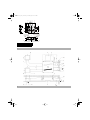
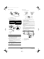
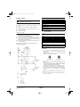
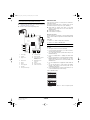
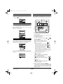
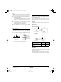
D
IMENSIONS
(See figure 1)
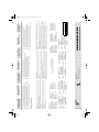
I
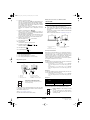
NSTALLATION
Installation position
■
Example of Installation (See figure 2)
1
Maintenance space for the heat exchange elements, air filters and
fans
2
Maintenance cover
3
Inspection hole
■
450 mm
4
Switch box
5
4x 14x40 mm Ceiling hook (Oval hole)
6
Exhaust air fan
7
OA (Outdoor air) Fresh air from outdoors
8
EA (Exhaust air) Exhaust air to outdoors
9
Supply air fan
10
SA (Supply air) Supply air to room
11
RA (Return air) Return air from room
12
Damper plate
13
Heat exchange elements
14
Air filters
15
Applicable duct
16
Nominal diameter
CAUTION
■
The appliance is designed to be a built-in
appliance. It shall not be accessible to the general
public. Adequate measures have to be taken to
prevent access by other than qualified persons.
■ Install the unit in a place strong enough to
support its weight.
Poor installation is hazardous. It also causes
vibrations and unusual operating noise.
■ Provide the service space and the inspection
holes.
(Be sure to provide the inspection holes to inspect the
air filters, the heat exchange elements and fans.)
■ Do not install the unit directly against a ceiling or
wall.
(If the unit is in contact with the ceiling or wall, it can
cause vibration.)
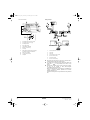
1 Air suction/discharge grille (option)
2 Inspection hole ■ 450 mm (field supply)
3 Maintenance space for the heat exchange elements, air filters and
fans
4 Duct (field supply)
5 Duct (Ø200) (field supply) or (*) Flexible duct (option)
6 EA (Exhaust air to outdoors)
7 Heat Insulator (field supply)
8 OA (Outdoor air) Fresh air from outdoors
9 Suspension bolt (field supply)
10 Gradient of down to outdoor ≥1/50
11 SA (Supply air to room)
12 RA (Return air from room)
13 Round hood (field supply)
14 Suspension bolt position
15 Additional external damper (field supply)
CAUTIONS
on installing the ducts
■ The parts marked with (*) are effective in reducing
blowing noise.
■ When using the unit at a quiet place, use the optional
silencer box and flexible duct at the part of the air
discharge outlet on the indoor side "SA" (supply air to
room) of the unit, to counter the noise.
■ When selecting installation materials, consider the
required volume of air flow and noise level in that
particular installation.
■ When the outdoor air infiltrates into the ceiling and the
temperature and humidity in the ceiling become high,
insulate the metal portions of the unit.
■ Access inside the unit is only allowed through the
service hole. Install grilles in case no ducts are
installed.
■ Unit sound pressure level is less than 70 dB(A).
4PEN586307-1_2019_06.book Page 2 Tuesday, July 9, 2019 1:29 PM

Installation manual
3
VAM150+250FC
Total Heat Exchanger
HRV (Heat Reclaim Ventilation)
4P586307-1 – 2019.06
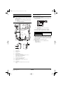
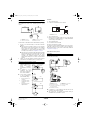
Method of installation
■ Installation of duct connecting flanges
Attach the provided duct connecting flanges using screws
(accessories).
Installation of HRV
■ Install the anchor bolt (M10 to 12) in advance.
Pass the metal suspension bracket through the anchor bolt and
secure the anchor bolt with washer and nut.
(Before installation, check for foreign objects such as vinyl and
paper remaining inside the fan housing.)
■ The metal suspension bracket is fitted on top of the standard
unit.
If the anchor bolt is long, install it on the bottom of the unit.
(Be sure to screw in the removed mounting screw on top to
prevent air leakage.)
Install the duct caution name plate property on the indoor side
(SA·RA) and outdoor side (EA·OA).
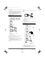
Duct connection
Do not connect the ducts as follows
1 The minimal radius of bends for flexible ducts are as follows:
300 mm duct: 200 mm diameter
375 mm duct: 250 mm diameter
2 To prevent air leakage, wind aluminium tape round the section
after the duct connecting flange and the duct are connected.
3 Install the opening of the indoor air intake as far as from the
opening of the exhaust suction.
4 Use the duct applicable to the model of unit used (Refer to the
outline drawing.)
5 Install the two outdoor ducts with down slope (slope of 1/50 or
more) to prevent entry of rain water. Also, provide insulation for
both ducts to prevent dew formation. (Material: Glass wool of
25 mm thick)
6 If the level of temperature and humidity inside the ceiling is
always high, install a ventilation equipment inside the ceiling.
7 Insulate the duct and the wall electrically when a metal duct is to
be penetrated through the metal lattice and wire lattice or metal
lining of a wooden structure wall.
1 Screw (accessories)
2 Duct connecting flange (accessories)
screws provided screws provided
VAM150 16 VAM650 24
VAM250 16 VAM800 24
VAM350 16 VAM1000 24
VAM500 16 VAM1500 24
VAM2000 24
1 Ceiling hook
2 Nut
3 Washer
4 Double nuts
NOTE
Remove the two fixing metals for transportation if it
prevents installation work. (Be sure to screw in the
removed mounting screw on the body side to prevent
air leakage.)
12
1
2
3
4
Extreme bend
Do not bend the duct over 90°
Multi bend
Reduce the diameter of the duct to be connected.
Do not reduce the duct diameter halfway.
1 Aluminium tape (field supply)
2 Insulation material (field supply)
3 Duct connecting flange (option)
4 Slope over 1/50
HRV
1
2
3
1
4
4PEN586307-1_2019_06.book Page 3 Tuesday, July 9, 2019 1:29 PM

VAM150+250FC
Total Heat Exchanger
HRV (Heat Reclaim Ventilation)
4P586307-1 – 2019.06
Installation manual
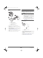
4
SYSTEM
Independent system
Air conditioner linked operation system
System Standard method
Related items in
Electric wiring
Independent system
• Up to 16 units can be controlled with the
remote controller for HRV. (A system with
two remote controls can be created in the
master/slave switching.)
• All HRV operations can be used and
indicated.
• Operation monitor output and humidifier
operation are possible using Adapter
PCB.
• Remote control cord should be procured
locally.
(Maximum cord length: 500 m)
"When connecting to
remote controller for
HRV" on page 15
Combined
operation system
with VRV systems
and Sky-air series
1-group linked
operation system
• A combined total of up to 16 air
conditioners and the HRV can be
controlled.
• The HRV ventilation mode can be
operated independently when air
conditioners are not being used.
• Using the local setting of the remote
controller for air conditioners, various
settings such as precool/pre-heat
reservation on/off, ventilation flow rate,
ventilation mode, etc.
"Standard 1-group
linked-control
system" on page 15
Multi-group
(2 or more) linked
operation system
• Since all VRV units are connected to a
single line in view of installation, all VRV
units are subjects for operation.
• If there are problems operating all VRV
units, do not use this system.
"Linked control with
more than two
groups" on page 16
HRV
HRV
1
2
1
Remote controller
for HRV
2
2-wire cord
(produced locally)
VRV
HRV
1 2
1
Remote controller
for air conditioner
(Remote controller
for HRV)
2
Remote controller
for air conditioner
VRV
VRV
VRV
VRV
HRV HRV
1 2
5 5
5 5
3 4
6
1
Group 1
4
Group 4
2
Group 2
5
Remote controller
for HRV
3
Group 3
6
Distant control
adapter
NOTE
■ Adapter PCB for external input/output BRP4A50A; Distant control adapter KRP2A51: Installation box KRP1BA101, mounting
plate EKMP25VAM.
■ Operation of two or more group is not possible with direct duct connection.
■ With VAM types, the direct duct connection shown can also be selected for 1-group operation systems.
System Standard method
Related items in
Electric wiring
Direct duct connection system
• The HRV will operate only when the air
conditioner fan is on.
• When the air conditioner is not being
used, the HRV can be operated in
circulation or ventilation modes.
• Other specifications are the same as
those of the standard system.
"Direct duct
connection system
for 1-group operation
system" on page 16
VRV
HRV
1 2 3
1
Remote controller
for air conditioner
(Remote controller
for HRV)
2
Remote controller
for air conditioner
3
Duct
4PEN586307-1_2019_06.book Page 4 Tuesday, July 9, 2019 1:29 PM

Installation manual
5
VAM150+250FC
Total Heat Exchanger
HRV (Heat Reclaim Ventilation)
4P586307-1 – 2019.06
Centralized control system (VRV system)
System Standard method
Related items in
Electric wiring
Centralized
control system
"All"/individual
control system
• Use of the on/off controller,
Adapter PCB for remote control
or schedule timer enables
centralized control of the entire
system.
(maximum of 64 groups)
• The on/off controller can turn
on or off the individual units.
• The schedule timer and on/off
controller can be used
together. However, the Adapter
PCB for remote control cannot
be used with another
centralized control device.
""All"/"individual"
control" on page 17
Zone control
system
• Use of the centralized
controller enables zone control
via the centralized control line.
(maximum of 64 zones)
• The central controller displays
the "Filter" indication and
abnormality warnings, and
enables resetting.
• The centralized controller
allows ventilation operation for
each zone independently.
"Zone control
system" on page 17
HRV
HRV
VRV VRV
VRV VRV
1 1
1 1
2
1
Remote controller
for air conditioner
2
Adapter PCB for
remote controller ,
Schedule timer,
On/Off controller
VRV VRV
HRV HRV HRV
HRV
2
1
4
3 3
1
Zone 1
3
Remote controller
for air conditioner
2
Zone 2
4
Central controller
NOTE
Wiring adapter for remote contact: BRP4A50A, Adapter PCB for remote control: KRP2A51, schedule timer. DST301B51, on/off
controller. DCS301B51, controller: DCS302C51, BRC1E53.
4PEN586307-1_2019_06.book Page 5 Tuesday, July 9, 2019 1:29 PM

VAM150+250FC
Total Heat Exchanger
HRV (Heat Reclaim Ventilation)
4P586307-1 – 2019.06
Installation manual
6
ELECTRIC WIRING
Connection of wiring
■ Connect the wires in accordance with the diagram of each
system.
■ All wiring must be performed by an authorized electrician.
■ All field supplied parts and materials and electric works must
conform to local codes.
■ Use copper wire only
Connection of wiring
■ A main switch or other means of disconnection, having a contact
separation in all poles, must be incorporated in the fixed wiring
in accordance with applicable legislation.
Do not turn on the main switch until all the wiring is complete.
■ A single switch can be used to supply power to units on the
same system. However, branch switches and branch circuit
breakers must be selected carefully.
■ Fit the power supply wiring of each unit with a switch and fuse as
shown in the drawing.
■ Be sure to give the electric grounding (earth) connection.
Complete system example
Component electrical specifications
Specifications for field supplied fuses and wire
Precautions
1 Do not connect wires of different gauge to the same power
supply terminal. Looseness in the connection may cause
overheating.
When connecting more than one wire to the power supply
wiring, use a 2 mm
2
(Ø1.6) gauge wire.
2 Keep total current of crossover wiring between indoor units less
than 12 A.
When using two power wiring of a gauge greater than 2 mm
2
(Ø1.6), branch the line outside the terminal board of the unit in
accordance with electrical equipment standards.
The branch must be sheathed so as to provide an equal or
greater degree of insulation as the power supply wiring itself.
3 Do not connect wires of different gauge to the same grounding
terminal. Looseness in the connection may deteriorate
protection.
4 Keep the power supply wiring distant from other wires to prevent
noise.
5 For remote controller wiring, refer to the "Installation manual of
the remote controller".
Before obtaining access to terminal devices, all power
supply circuits must be interrupted.
Power supply wiring
Transmission wiring
Switch
Fuse
1 Outdoor unit
2 Indoor unit
3 Power supply
4 Main switch
5 Remote controller
VRV
VRV
VRV
HRV
HRV
1
2
2
3
4
5
5
VAM
150F 250F
Units
Type
JVE, 5VE
50 Hz
Power supply Max. 264 V/Min. 198 V
60 Hz
Power supply Max. 242 V/Min. 198 V
Power supply
(*)
(*) MCA: Min. Circuit Amps
MFA: Max. Fuse Amps
KW: Motor Rated Output
FLA: Full Load Amps
MCA (A)
0.9 0.9
MFA (A)
16 16
Fan motor
(*)
KW (kW)
0.03x2 0.03x2
FLA (A)
0.4x2 0.4x2
NOTE
For details, refer to ELECTRICAL DATA.
VAM
150F 250F
Type
JVE, 5VE
Power supply wiring
Field supplied fuses
16 A
Wire
H05VV-U3G
Size
Wire size must comply with local codes
Transmission wiring
Wire
Shield wire (2 wire)
Size
0.75-1.25 mm
2
Same gauge wires Different gauge wires
4PEN586307-1_2019_06.book Page 6 Tuesday, July 9, 2019 1:29 PM

Installation manual
7
VAM150+250FC
Total Heat Exchanger
HRV (Heat Reclaim Ventilation)
4P586307-1 – 2019.06
View seen from VRV Wiring example
■ All transmission wiring except for the remote controller wires is
polarized and must match the terminal symbol.
■ Use shield wire in transmission wiring. Ground the shield of the
shield wire to " ", at the grounding screw, with the C-cup
washer.
■ Sheathed wire materials may be used for transmission wiring,
but they are not suitable for EMC (Electromagnetic
Compatibility) (European Directive).
When using sheathed wire, electromagnetic Compatibility must
conform to Japanese standards stipulated in the Electric
Appliance Regulatory Act.
Transmission wiring need not be grounded when using sheathed
wire.
1 2
5
3
46
7
8
A
B
C
1 Terminal board for transmission wiring
2 Terminal board for power supply
3 Grounding terminal
4 Power supply wiring
5 Clamp material (attached)
6 Remote controller wiring
7 Unit wiring
8 Field supply wire/Earth terminal (attached)
Ground the shield part of shielded wire.
A Earth screw (attached)
B C-cup washer (attached)
C Shield part
VRV
HRV
P1
P1
P1
P2
P2
P2
L
N
12
Out
VRV HRV
L
N
LN 1122
P1 P2 F1 F1 T1 T1
P2 P1 F1 F2 J2 JC L NJ1
1
2
5
3
44
6
7
6
1 Outdoor unit/BS unit
2 Switch box
3 Indoor unit
4 Power supply 220-240 V~50 Hz
5 Remote controller (VRV)
6 Transmission wiring
7 Remote controller (HRV)
4PEN586307-1_2019_06.book Page 7 Tuesday, July 9, 2019 1:29 PM

VAM150+250FC
Total Heat Exchanger
HRV (Heat Reclaim Ventilation)
4P586307-1 – 2019.06
Installation manual
8
Opening the switch box Required electrical connections for possible additional field
supplied external damper
The external damper prevents the intake of outdoor air if the HRV is
switched off. (Refer to figure 2, item 19).
1. The HRV's main unit PCB operates the HRV and supplies power
for the external damper.
Source voltage supply starts when HRV starts operating.
Source voltage supply is stopped when HRV is switched off.
2. Required electrical connections
Connect one end of the accessory harness to the X1/X2
connector on the PCB and the other end to the harness leading
to the external damper via a insulated splices-closed barrel
connector (0.75 mm
2
).
Make sure that the wire is released from strain.
3. Required settings
• Mode No.: 18 (Group control) or 28 (Individual control)
• Setting switch No.: 3
• Setting position No.: 03
CAUTION
Before opening the cover, be sure to turn off the power
switches of the main units and other devices connected
with the main units.
■ Remove the screw securing the cover and open the
switch box.
■ Secure the power cord control wires with the clamp,
as shown in the next figures.
1 Switch box
2 Terminal board
3 Grounding terminal
4 Control PCB
5 Power supply cable
6 BRP4A50A (optional accessory)
7
Double or reinforced insulated flexible cable (0.75 mm
2
) to
external damper or heater (field supply)
8 KRP2A51 (optional accessory)
9 Transmission wiring to optional controller
10 Transmission wiring terminal board
11 Wiring for connection of additional damper or heater
12 Switch box cover
13 Securing screw
14
Insulated splices-closed barrel connector (0.75 mm
2
) (field
supply)
1
2
5
11
4
3
7
14
8 9
6
X9A
P2 P1 F1F2
X2 X1
10
5 6 7
8
9
12
13
13
Supply voltage Connected load capacity
220 V
≤0.5 A230 V
240 V
2
1
PCB
X1/X2
3
1 HRV main unit
2 External damper
3 Earth to external damper, if no class II construction
(EN60335-2-40)
4PEN586307-1_2019_06.book Page 8 Tuesday, July 9, 2019 1:29 PM

Installation manual
9
VAM150+250FC
Total Heat Exchanger
HRV (Heat Reclaim Ventilation)
4P586307-1 – 2019.06
How to install the optional adapter circuit board
(KRP2A51)
1 Attach the optional mounting plate (EKMP25VAM).
2 Attach the optional PCB (KRP2A51) in the installation box
(KRP1BA101).
3 Follow the installation instructions provided with the option kit
(KRP2A51 and KRP1BA101).
4 Guide the PCB wire through the dedicated holes and attach it as
instructed in "Opening the switch box" on page 8.
5 Attach the option to the optional mounting plate as shown in the
figure.
6 Fasten the switch box when the wires are connected.
How to install the optional heater control kit (BRP4A50A)
When operating the HRV units at or below –10°C of the outdoor air
temperature, use a field supplied preheater to preheat outdoor air.
The BRP4A50A kit is required to have an ON/OFF delay control
when a preheater is used (initial setting is required).
Install the heater control kit to the outside of the switch box of the
HRV unit as shown below.
1 Follow the installation instruction provided with option kit
(BRP4A50A) to assemble the heater control kit.
2 Attach the heater control kit to the switch box as shown in the
figure above.
3 Guide the PCB wire the dedicated holes and attach it as
instructed in "Opening the switch box" on page 8.
4 Fasten the switch box when the wires are connected.
1 Switch box
2 KRP2A51 (optional accessory)
3 KRP1BA101 (installation box)
4 Screw (supplied with the installation box)
5 EKMP25VAM (mounting plate)
6 Screw
1
5
4
4
2
2 + 3
4
3
6
CAUTION
■ For electric heater, safety devices, and installation
location, follow the standards or regulations of each
country.
■ Use a nonflammable duct for the electric heater. Be
sure to keep a distance of ≥2 m between the heater
and HRV unit for safety.
■ Use a different power supply and different circuit
breaker for the HRV units and electric heaters.
■ For setting the initial setting on the remote controller,
see 19(29)-8-03 or 19(29)-8-04 in chapter "List of
settings" on page 12.
1 Switch box
2 BRP4A50A (optional accessory)
3 Screw
3
2
1
4PEN586307-1_2019_06.book Page 9 Tuesday, July 9, 2019 1:29 PM

VAM150+250FC
Total Heat Exchanger
HRV (Heat Reclaim Ventilation)
4P586307-1 – 2019.06
Installation manual
10
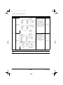
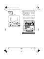
Power cord connection, control wire terminals and switches
on the electronic control unit (printed circuit board)
■ Connect the power cord to the L and N terminals.
■ Secure the power cord with the power cord clamp, as shown in
"Opening the switch box" on page 8.
■ Be sure to connect the electric grounding (earth).
CONFIGURATION
Using the remote controller of the VRV-system air conditioner to
make HRV unit settings
The settings (format: XX(XX)-X-XX), for example 19(29)-1-02, that
are uned in this chapter are composed of 3 parts, divided by "-":
■ Mode number: for example 19(29), where 19 is the mode
number for group settings and 29 is the mode number for
individual settings.
■ Switch number: for example, 1
■ Position number: for example, 02.
Operating procedure
You can use either the user interface of the heat reclaim ventilation
units or of the air conditioner to adjust the heat reclaim ventilation unit
settings.
Initial setting
1 Mode nos. 17, 18 and 19: Group control of HRV units.
2 Mode nos. 27, 28 and 29: Individual control
To change the settings with BRC1E53
Make sure that the switch box lids on the heat reclaim ventilation unit
are closed.
1 Shortly press a button to turn on the screen light.
2 Press and hold the Cancel button (1) for at least 4 seconds to
enter the Service Settings menu.
3 Go to Field Settings with the Up/Down buttons and press the
Menu/Enter button (2).
4 Press the Left/Right buttons to highlight the number under
Mode.
5 Press the Up/Down buttons to select the required mode number.
Result: Depending on the mode number that you select,
starting at 20, you will also have to select a unit number, for the
individual control.
6 Use the Left/Right buttons to highlight the number under Unit
No.
7 Use the Up/Down buttons to select an indoor unit number.
Selecting a unit number is NOT necessary when you are
configuring the entire group.
8 Use the Left/Right buttons to select a position number (0 to 15)
for the switch number that you want to change.
In case of individual settings:
In case of group settings:
9 Use the Up/Down buttons to select the required position
number.
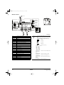
1 Power supply 10 Centralized control
2 Terminals 11 Remote controller
3 Supply air fan 12 Factory setting (no operation
if remote controller is
attached)
4 Exhaust air fan 13 BRP4A50A (optional
accessory)
5 Damper 14 Damper
6 Primary 15 Indoor air thermistor
7 Power supply PCB 16 Outdoor air thermistor
8 Secondary
9 No voltage external input
7
16
3 4
1112
5
1
LN
2
15
14
13
10 9
6
8
X9A
X5A
X12A
X13A
X27A
X1A X2A
X3A
X8A
P2
SS1
P1 F1 F2 J1 J2 J3 JC
X2 X1 X2 X1
NOR
H
M
Field Settings
Unit No.
0
Mode
20
SettingReturn
Field Settings
Mode
10
SettingReturn
4PEN586307-1_2019_06.book Page 10 Tuesday, July 9, 2019 1:29 PM

Installation manual
11
VAM150+250FC
Total Heat Exchanger
HRV (Heat Reclaim Ventilation)
4P586307-1 – 2019.06
10 Press the Menu/Enter (2) button and confirm the selection with
Ye s .
11 You have completed all the changes, press the Cancel button (1)
twice to return to the normal mode.
To change the settings with BRC301B61
Make sure that the switch box lids on the heat reclaim ventilation unit
are closed.
1 With the unit in normal mode, press the Inspection/Trial button
(1) for more than 4 seconds to enter the local setting mode.
2 Use the Ventrilation mode button (up - 2) and the Airflow rate
button (down - 2) to select a mode number.
Result: The code display is blinking.
3 To configure settings for individual units under group control,
press the Timer setting on/off button (3) and select the number
of that unit that you want to configure.
4 To select the setting switch number press the top section of the
Timer button (4). To select the setting position number, press the
lower section of the Timer button (5).
5 Press the Program/Cancel button (6) once, to enter the setting.
Result: The code display stops blinking and lights up.
NoYes
Field Settings
Save the settings?
SettingReturn
2
1
NOTE
Setting 18(28)-11 CANNOT be selected with the user
interface.
3
6
1
45
2
SETTING
4PEN586307-1_2019_06.book Page 11 Tuesday, July 9, 2019 1:29 PM

VAM150+250FC
Total Heat Exchanger
HRV (Heat Reclaim Ventilation)
4P586307-1 – 2019.06
Installation manual
12
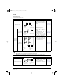
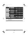
List of settings
Mode No.
Setting switch
No. Description of Setting
Setting position No.(Caution *1.)
Group
settings
Individual
settings 01 02 03 04 05 06
17 27
0
Filter cleaning time setting
Approx. 2500
hours
Approx. 1250
hours
No
counting
–––
2 Precool/preheat on/off setting
Off On – – – –
3 Precool/preheat time setting
30 min 45 min 60 min – – –
4 Fan speed initial setting
Normal Ultra high – – – –
5
Yes/No setting for direct duct connection
with VRV system
No duct (Air
flow setting)
With duct (fan
off)
––––
Setting for cold areas (Fan operation
selection for heater thermo OFF)
––
No duct With duct
Fan off Fan L Fan off Fan L
8
Centralized zone interlock setting
No Yes
Priority on
operation
–––
9 Preheat time extension setting
0 min 30 min 60 min 90 min – –
18 28
0
External signal JC/J2
Last
command
Priority on
external input
––––
1 Setting for direct Power ON
Off On – – – –
2 Auto restart setting
Off On – – – –
3
Humidification operation setting Only heating Always
Only heating Always – –
External output signal switching (between
X1 and X2)
humidification
output
humidification
output
fan damper
output
fan damper
output
––
4
Indication of ventilation mode/No
indication
Indication
No Indication – – – –
7
Fresh up air supply/exhaust setting
No Indication No Indication Indication Indication – –
Supply Exhaust Supply Exhaust – –
8
External input terminal function selection
(between J1 and JC)
Fresh-up Overall alarm
Overall
malfunction
Forced off Fan forced off
Air flow
increase
9
BRP4A50A Output switching selection
between X3 and X4
Heater output Error output – – – –
19 29
8
Stop ventilation by automatic ventilation
air flow control
Allowed
Not allowed Allowed Not allowed – –
Fan residual operation
Off
Off
Heater
operation
Heater
operation
––
NOTE
■ Factory settings are grey marked.
■ Group number setting for central controller
Mode No. 00: Group controller
Mode No. 30: Individual controller
For the setting procedure, see "Group number setting for central control" in the operation manual of either the ON/OFF
controller or the central controller.
4PEN586307-1_2019_06.book Page 12 Tuesday, July 9, 2019 1:29 PM

Installation manual
13
VAM150+250FC
Total Heat Exchanger
HRV (Heat Reclaim Ventilation)
4P586307-1 – 2019.06
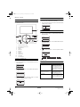
About the controller
Controller for VRV system air conditioner
Please read the manual supplied with the controller (BRC1E53) for
more detailed instructions.
To change the ventilation rate
1 Press the Menu/Enter button to display the main menu.
2 Press the Up/Down buttons to select Ventilation and press the
Menu/Enter button.
3 Press the Up/Down buttons to select Ventilation Rate and press
the Menu/Enter button.
4 Press the Up/Down buttons to change the setting to Low or High
and press the Menu/Enter button to confirm.
To select ventilation mode
Ventilation mode is used when cooling or heating is not necessary, so
only the heat reclaim ventilation units are operating.
1 Press the Operation Mode Selector button several times until the
ventilation mode is selected.
To change the ventilation mode
1 Press the Menu/Enter button to display the main menu.
2 Press the Up/Down buttons to select Ventilation and press the
Menu/Enter button
3 Press the Up/Down buttons to select Ventilation Mode and press
the Menu/Enter button
4 Press the Up/Down buttons to select the required ventilation
mode.
Ventilation modes
You can change the ventilation mode in the main menu.
1 Operation Mode Selector button
2 Fan Speed/Airflow Direction button
3 Menu/Enter button
4 Up button
5 Down button
6 Right button
7 Left button
8 ON/OFF button
9 Operation lamp
10 Cancel button
11 LCD with backlight
3
10
11
81
9
4, 5, 6, 72
Airflow Direction
Individual Air Direction
Quick Start
Ventilation
Energy Saving Options
Schedule
1/2
Setting
Return
Main Menu
2/2
Ventilation Rate
Ventilation Mode
Ventilation
SettingReturn
Ventilation Rate
Ventilation
High
SettingReturn
Mode Description
Auto mode Using information from the air
conditioner (cooling, heating, fan,
and set temperature) and heat
reclaim ventilation unit (indoor and
outdoor temperatures), this mode
automatically switches between heat
reclaim ventilation mode and bypass
mode.
Heat reclaim ventilation mode
(energy reclaim ventilation)
Outdoor air is supplied to the room
after passing through a heat
exchange element, where heat is
exchanged with the room air.
Bypass mode The indoor air bypasses the heat
exchange element. This means that
outdoor air is supplied to the room
without heat exchange with the room
air.
Vent
Airflow Direction
Individual Air Direction
Quick Start
Ventilation
Energy Saving Options
Schedule
1/2
Setting
Return
Main Menu
2/2
Ventilation Rate
Ventilation Mode
Ventilation
SettingReturn
Bypass
2/2
Ventilation mode
Ventilation
SettingReturn
Bypass
Energy Reclain Vent.
Auto
4PEN586307-1_2019_06.book Page 13 Tuesday, July 9, 2019 1:29 PM

VAM150+250FC
Total Heat Exchanger
HRV (Heat Reclaim Ventilation)
4P586307-1 – 2019.06
Installation manual
14
Time to clean filter indication
When the filter pressure drop becomes too large, the following
message or icon is displayed at the bottom of the basic screen: Time
to clean filter or . Clean the filters.
To remove the Time to clean filter indication
1 Press the Menu/Enter button.
2 Press the Up/Down buttons to select Reset Filter Indicator.
3 Press the Menu/Enter button.
Result: You return to the basic screen. The Time to clean filter
indication is no longer displayed.
About error indications
If an error occurs, there is an error icon in the basic screen and the
operation lamp blinks. If a warning occurs, ONLY the error icon blinks
and the operation lamp does NOT. Press the Menu/Enter button to
display the error code or warning and contact information.
The error code blinks and the contact address and model name
appear as shown below. In this case, notify your dealer about the
error code.
Controller for heat reclaim ventilation units
For non-independent systems, starting, stopping and setting timer is
NOT possible with this controller (BRC301B61). In such cases, use
the air conditioner controller (BRC1E53) or the central controller.
1. Operation lamp
This red pilot lamp lights up while the unit is in operation.
2. Operation/Stop button
Press this button once and the unit starts to operate. Press this
button again and the unit stops.
3. Air flow rate changeover button
Use this button to change the air flow to " " Low, " "
High mode, " FRESH UP" Low Fresh-up, or " FRESH
UP" High Fresh-up mode.
When this indication does NOT show, the
volume of outdoor air supplied into the room
and that of the room air exhausted outdoor is
equal.
For "FRESH UP" operation
• If the Fresh-up setting is set to "Fresh up air
supply": The volume of outdoor air supplied
into the room is larger than that of room air
exhausted outdoors. This prevents odours and
moisture from kitchens and toilets from flowing
into the room. This is the factory setting.
• If the Fresh-up setting is set to "Fresh up air
exhaust": The volume of room air exhausted
outdoors is larger than that of outdoor air supplied into the room.
This prevents hospital odours and airborne micro-organisms from
flowing out of the room into the corridors.
To change this setting, see "List of settings" on page 12.
4. Ventilation mode changeover button
" " Automatic mode
The unit's temperature sensor automatically
changes the operation mode of the unit to Bypass
mode or heat reclaim ventilation mode.
" " Heat reclaim ventilation mode
In this mode, the outdoor air passes through the
heat exchange element to effect heat reclaim
ventilation.
" " Bypass mode
In this mode, the outdoor air does not pass
through the heat exchange element, but passes it
to effect Bypass ventilation.
5. Indication of operation control method:
When the operation of the heat reclaim ventilation units is linked
to the air conditioners, this indication may be displayed. While
this indication is displayed, the heat reclaim ventilation units
CANNOT be turned on or off with the controller of the heat
reclaim ventilation units.
Cool
Set to
28°C
Time to clean filter
1/3
Setting
Return
Reset Filter Indicator
Airflow Direction
Individual Air Direction
Quick Start
Ventilation
Energy Saving Options
Main Menu
Cool
Set to
28°C
Cool
Set to
28°C
Error : Push Menu Button
Contact Info
0123
–
4567
–
8900
Indoor Model
–––
/000
Outdoor Model
–––
/000
Error Code:A1
Return
TEST
FRESH UP
12
8
4
3
9
10
13
12
11
6
FRESH UP
FRESH UP
A
(
(
(
(
4PEN586307-1_2019_06.book Page 14 Tuesday, July 9, 2019 1:29 PM

Installation manual
15
VAM150+250FC
Total Heat Exchanger
HRV (Heat Reclaim Ventilation)
4P586307-1 – 2019.06
6. Indication of operation standby:
This icon indicates that the unit is precooling/preheating. The
unit's start-up is delayed until precooling/preheating is finished.
Precooling/preheating means that the heat reclaim ventilation
units are NOT started while linked air conditioners are starting
up, for example, before office hours.
During this period, the cooling or heating load is reduced to
bring the room temperature to the set temperature in a short
time.
7. Indication of centralized control:
When a remote controller for air conditioners or devices for
centralized control are connected to the heat reclaim ventilation
units, this indication may be displayed.
While this indication is displayed, you may NOT be able to turn
the heat reclaim ventilation units on or off, or use the timer
function with the controller of the heat reclaim ventilation unit.
8. Indication of air filter cleaning
When the display shows " ", clean the filter.
9. Filter signal reset button
10. Inspection button
Use this button only when servicing the unit.
11. Schedule timer button: / or .
This button enables or disables the schedule timer.
12. Time adjust button: .
13. Programming button: / .
To set the timer
1 Press the schedule timer button.
2 Press the time adjust button to set the time.
3 Press the programming button to save the setting.
Independent system
When connecting to remote controller for HRV
For raising the remote-controlled ventilation air flow rate from "High"
to "Ultra-High", connect the remote controller for the air-conditioner to
HRV and make settings on site.
(Refer to "List of settings" on page 12.)
Keep the switch on the PCB at the factory setting.
Wiring and connections in combination with
"VRV-SYSTEM"
Standard 1-group linked-control system
■ The remote control of the air conditioner can be used to control
up to 16 air conditioner indoor units and HRV units.
■ Initial settings can be made for the functions of the HRV units
(pre-cool/pre-heat, ventilation air flow, ventilation mode and
"Fresh-Up").
Use the remote controller of the air conditioner to make the initial
settings for the HRV units.
Refer to "Initial setting" under Item "Configuration" on page 10"
Pre-cool/pre-heat function
When the pre-cool/pre-heat function is set, the HRV unit switches on
at the preset time (30, 45 or 60 minutes) after the VRV-system air
conditioner begins cooling or heating operation. The function is set
OFF at the factory. Therefore, to use this function, the initial setting
must be made using the remote controller of the air conditioner.
If the air conditioner is re-started within two hours after the operation
was stopped, this function does not operate.
Example 1:
To switch on the pre-cool/pre-heat function, and turn on the HRV unit
60 minutes after the air conditioner is turned on.
• Set the mode No. to "17" for group control, or "27" for individual
control, the setting switch No. to "2" and the setting position No.
to "02"
• Set the mode No. to "17" for group control, or "27" for individual
control, the setting switch No. to "3" and the setting position No.
to "03"
Example 2:
To switch the ventilation air flow to ultra high setting. (The units are
set at the high air flow setting at the factory)
• Set the mode No. to "17" for group control, or "27" for individual
control, the setting switch No. to "4" and the setting position No.
to "02"
Example 3:
When the remote controller is connected, keep the switches on the
heat reclaim ventilation unit PCB at the default factory settings.
Factory settings: Do NOT change the switch
settings. SS1 is a setting switch for special
purposes. Changing the settings will stop the unit
from operating normally.
P1
P2 P1
P2
P1 P2P1 P2
HRV
HRV
1
2
5
3 4
6
1
Master unit
4
Switch position: Master
2
Slave unit
5
Remote controller for HRV
3
Switch position: Slave
6
Maximum connection line length:
500 m
NOR
SS1
H
M
Air ventilation rate
setting using remote
control
Default factory settings
When set as in example
2
Low Low (L) air flow rate Low (L) air flow rate
High High (H) air flow rate
Ultra-high (UH) air flow
rate
Factory settings: Do NOT change the switch
settings.
SS1 is a setting switch for special purposes.
Changing the settings will stop the unit from
operating normally.
P1
P2
P1
P2
P1
P2
P1 P2
VRV HRV
1 2
3
1
Remote controller for air
conditioner
3
Connecting line can be extended
up to 500 m maximum
2
Remote controller for HRV
NOR
SS1
H
M
4PEN586307-1_2019_06.book Page 15 Tuesday, July 9, 2019 1:29 PM

VAM150+250FC
Total Heat Exchanger
HRV (Heat Reclaim Ventilation)
4P586307-1 – 2019.06
Installation manual
16
Direct duct connection system for 1-group operation system
Line connections and the settings of the switches on the HRV unit
PCB should be the same as for "Standard system for 1-group
system".
Set the switches of the HRV unit PCB to the default factory settings.
1 Be sure to set the initial settings to Direct duct connection:
Enabled.
■ When the remote controller for HRV is not yet connected,
initial settings can be performed using the air conditioner
remote control. Set the mode number to "17", the setting
switch number to "5", and the setting position number to "02"
according to the procedure in "Configuration" on page 10.
■ When the remote controller for HRV, initial settings should be
performed using the remote controller for HRV. Set the same
numbers as described above when using the remote
controller for air conditioner according to the procedure
"Making initial settings" in the remote control instruction
manual.
2 Settings for other HRV functions should be made using the
same method as in "Standard system for 1-group system".
Linked control with more than two groups
■ Mount the optional
KRP2A51 Adapter PCB for
remote control on the
electric component
mounting base of one HRV
unit.
■ A maximum of 64 air
conditioners and HRV
units can be connected to
the F1 and F2 terminals.
■ Use the remote controller
of the air conditioner to
make the initial settings.
Procedure
1 Turn off the main power.
2 Connect the air-conditioner remote controller.
3 Turn on the main power.
4 Make the remote controller settings on site; Set the collective
zone interlock to ON. Mode number "17", setting switch number
"8" and setting position number "02".
5 Turn off the main power.
6 Disconnect the remote controller.
Now the on-site settings are complete.
For raising the remote-controlled ventilation air flow rate "High" to
"Ultra-High", connect the remote controller for the air conditioner to
HRV and make settings on site. (Refer to "Initial setting" under item
"Configuration" on page 10.)
Centralized control system
"All" control
When using Adapter PCB for remote control (KRP2A51,52,53) or
schedule timer (DST301B51)
■ A maximum of 64 air conditioners and HRV units can be
connected to the F1 and F2 terminals.
■ This system does not required group number setting for
centralized control. (auto-address system)
1 Remote controller for air
conditioner
2 Connecting line can be
extended up to 1000 m
maximum
3 Optional distant control
adapter KRP2A51
P1
P2
P1
P2
P1
P2
P1
P2
VRV
1
2
3
4
1
Remote controller for air
conditioner
3
Maximum connection line length:
500 m
2
Remote controller for HRV
4
Medium (M) air flow rate
VRV
VRV
HRV 1
HRV 2
X11A
F1 F2
P1
P2
P1 P2
F1 F2
F1 F2
1
2
3
P1
P2
P1
P2
P1
P2
HRV 1
1
2
1
Remote controller for air
conditioner
2
Remote controller for HRV
HRV 1
X11A
HRV 2
VRV 1
F1 F2
D1 D2
F1 F2
F1 F2
F1 F2
P1
P2
P1 P2
P1
P2
P1 P2
1
2
7
5
3
4
6
1
Remote controller for air
conditioner
5
Adapter PCB for remote control
(KRP2A51)
2
Remote controller for HRV
6
Distant control adapter
3
Connecting line can be extended
up to 1000 m maximum
7
On/Off signal
4
Schedule timer (DST301B51)
4PEN586307-1_2019_06.book Page 16 Tuesday, July 9, 2019 1:29 PM

Installation manual
17
VAM150+250FC
Total Heat Exchanger
HRV (Heat Reclaim Ventilation)
4P586307-1 – 2019.06
■ The Adapter PCB for remote control and schedule timer cannot
be used together.
■ The Adapter PCB for remote control can be mounted on the
electric component mounting base of either the HRV unit or air
conditioner. (The HRV unit can accept only the KRP2A51)
■ For raising the remote-controlled ventilation air flow rate from
"High" to "Ultra-High", connect the remote controller for the air-
conditioner to HRV and make settings on site.
(Refer to "Initial setting" under item "Configuration" on page 10.)
"All"/"individual" control
When using the on/off controller (DCS301B51)
■ A maximum of 64 air conditioners and HRV units can be
connected to the F1 and F2 terminals.
■ This system allows connection of four on/off controllers.
■ It is necessary to assign a central control group number to each
HRV unit and air conditioner.
Regarding the setting of the group number, refer to the section
on "the centralized control group number setting" in the
operating instructions of the On/off controller.
■ Use the remote controller of the air conditioner to make the initial
settings.
Example:
Follow the procedure below to set the centralized group No. 2-05 to
HRV 1.
Procedure
1 Set the central control group number using the local setting on
the remote controller.
Mode No.: "00"
Central control group No.: "2-05"
The setting is now complete.
For the ventilation air flow setting, follow the procedure described in
the section ""All" control" on page 16.
Zone control system
■ A maximum of 64 air conditioners and HRV units can be
connected to the F1 and F2 terminals.
■ The HRV units will turn on and off in according with the zone
operation command from the centralized controller.
12
3
4
F1
F2
F1
F2
F1
F2
F1
F2
F1 F2
F1 F2
F1 F2
F1
F2
P1
P2
P1
P2
P1 P2
P1 P2
HRV 1
HRV 2
VRV 1
1
2
5
3
4
1
Remote controller for air
conditioner
4
Schedule timer
2
Remote controller for HRV
5
On/Off controller
3
Connecting line can be extended
up to 1000 m maximum
P1
P2
P1
P2
P1
P2
HRV 1
1
2
1
Remote controller for air
conditioner
2
Remote controller for HRV
F1
F2
F1 F2
F1
F2
F1
F2
F1
F2
P1
P2
P1
P2
P1
P2
P1
P2
HRV 1
HRV 2
HRV 3
VRV
1
2
5
3
4
3
1
Zone 1
4
Connecting line can be extended
up to 1000 m maximum
2
Zone 2
5
Centralized controller
(DCS302C51
3
Remote controller for HRV
4PEN586307-1_2019_06.book Page 17 Tuesday, July 9, 2019 1:29 PM
Pagina se încarcă...
Pagina se încarcă...
Pagina se încarcă...
Pagina se încarcă...
-
 1
1
-
 2
2
-
 3
3
-
 4
4
-
 5
5
-
 6
6
-
 7
7
-
 8
8
-
 9
9
-
 10
10
-
 11
11
-
 12
12
-
 13
13
-
 14
14
-
 15
15
-
 16
16
-
 17
17
-
 18
18
-
 19
19
-
 20
20
-
 21
21
-
 22
22
-
 23
23
-
 24
24


Daikin VAM250FC Ghid de instalare
- Tip
- Ghid de instalare
- Acest manual este potrivit și pentru
în alte limbi
- English: Daikin VAM250FC Installation guide
- italiano: Daikin VAM250FC Guida d'installazione
Lucrări înrudite
-
Daikin R32 Ghid de instalare
-
Daikin ARXP25L5V1B Ghid de instalare
-
-
Daikin FWF04B7TV1B Ghid de instalare
-
-
Daikin R32 Split Series Ghid de instalare
-
-
-
Daikin FTXM71M + RXM71M Manualul proprietarului
-
Alte documente
-
LG LZ-H200GBA2.ENWALEU Manual de utilizare
-
SIGURO SGR-FC-H350W Manual de utilizare
-
Mark ERV Series Technical Manual
-
Well PIGEON Ghid de instalare
-
Dometic TwinBoost4000, TwinBoost4000E, TwinBoost6000, TwinBoost6000E Manual de utilizare
-
Samsung AC090HCADKH/EU Manualul utilizatorului
-
Samsung AC071JXSCEH/EU Manual de utilizare
-
Samsung AC120MXADKH/EU Ghid de instalare
-
Samsung AC100RXADKG/EU Manual de utilizare
-