Master BV 400 4035.188 E19R2 Manualul proprietarului
- Categorie
- Incalzitoare de spatiu
- Tip
- Manualul proprietarului

4035.188 Edition 19 Rev. 2
BV 400
USER AND MAINTENANCE BOOK
en
LIBRETTO USO E MANUTENZIONE
it
BEDIENUNGS- UND WARTUNGSANLEITUNG
de
MANUAL DE INSTRUCCIONES PARA EL USO Y MANTENIMIENTO
es
MANUEL D’UTILISATION ET DE MAINTENANCE
fr
HANDLEIDING VOOR GEBRUIK EN ONDERHOUD
nl
MANUAL DE USO E MANUTENÇÃO
pt
VEJLEDNING OM BRUG OG VEDLIGEHOLDELSE
da
KÄYTTÖ- JA HUOLTO-OHJE
HEFTE FOR BRUK OG VEDLIKEHOLD
no
ANVÄNDAR- OCH UNDERHÅLLSHANDBOK
sv
INSTRUKCJA OBSŁUGI I KONSERWACJI
pl
РУКОВОДСТВО ПО ЭКСПЛУАТАЦИИ И ТЕХНИЧЕСКОМУ ОБСЛУЖИВАНИЮ
ru
PŘÍRUČKA PRO POUŽITÍ A ÚDRŽBU
cs
HASZNÁLATI ÉS KARBANTARTÁSI KÉZIKÖNYV
hu
PRIROČNIK Z NAVODILI ZA UPORABO IN VZDRŽEVANJE
sl
KULLANIM VE BAKIM K
i
TAPÇIĞI
tr
KNJIŽICA O UPORABI I ODRŽAVANJU
hr
NAUDOJIMO IR PRIEŽIŪROS KNYGELĖ
lt
LIETOŠANAS UN TEHNISKĀS APKOPES GRĀMATIŅA
lv
KASUTUS- JA HOOLDUSJUHEND
et
MANUAL DE UTILIZARE ŞI ÎNTREŢINERE
ro
PRÍRUČKA PRE POUŽITIE A ÚDRŽBU
sk
НАРЪЧНИК ЗА ИЗПОЛЗВАНЕ И ПОДДРЪЖКА
bg
КЕРІВНИЦТВО З ЕКСПЛУАТАЦІЇ Й ТЕХНІЧНОГО ОБСЛУГОВУВАННЯ
uk
KNJIŽICOM O UPOTREBI I ODRŽAVANJU
bs
ΕΓΧΕΙΡΙΔΙΟ ΧΡΗΣΗΣ ΚΑΙ ΣΥΝΤΗΡΗΣΗΣ
el
使用和维护手册
zh
ПАЙДАЛАНУ ЖӘНЕ ТЕХНИКАЛЫҚ ҚЫЗМЕТ КӨРСЕТУ ЖЕТЕКШІЛІГІ
kk
Dantherm S.p.A.
Via Gardesana 11, -37010-
Pastrengo (VR), Italy
Dantherm S.p.A.
Виа Гардесана 11, 37010
Пастренго (Верона), Италия
Dantherm Sp. z o.o.
ul. Magazynowa 5A,
62-023 Gądki, Poland
Dantherm Sp. z o.o.
ул. Магазинова, 5A,
62-023 Гадки, Польша
Dantherm LLC
ul. Transportnaya - 22 ownership 2,
142802, STUPINO, Moscow region, Russia
ООО «Дантерм»
Ул. Транспортная, владение 22/2,
142802, г.Ступино, Московская обл., РФ
Dantherm China LTD
Unit 2B, 512 Yunchuan Rd.,
Shanghai, 201906, China
Dantherm China LTD
Юньчуань роад, 512, строение 2В,
Шанхай, 201906, Китай
Dantherm SP S.A.
C/Calabozos, 6 Polígono Industrial, 28108
Alcobendas (Madrid) Spain
Dantherm SP S.A.
Ц/Калабозос, 6 Полигоно Индустриал,
28108 Алкобендас (Мадрит) Испания

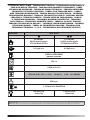
TECHNICAL DATA TABLE - TABELLA DATI TECNICI - TECHNISCHE DATENTABELLE
- TABLA DE DATOS TÉCNICOS - TABLEAU DES DONNÉES TECHNIQUES - TABEL
TECHNISCHE GEGEVENS - TABELA DE DADOS TÉCNICOS - TEKNISK DATATABEL
- TEKNISTEN TIETOJEN TAULUKKO - TABELL FOR TEKNISKE DATA - TABELL
MED TEKNISKA EGENSKAPER - TABELA DANYCH TECHNICZNYCH - ТАБЛИЦЕ
ТЕХНИЧЕСКИХ ДАННЫХ - TABULKA TECHNICKÝCH ÚDAJŮ - MŰSZAKI ADATOK
TÁBLÁZATA - TEHNIČNI PODATKI - TEKNİK VERİLER TABLOSUNDA - TABLICI
S TEHNIČKIM PODACIMA - TECHNINIŲ DUOMENŲ LENTELĖJE - TEHNISKO
DATU TABULA - TEHNILISTE ANDMETE TABEL - TABELUL CU DATE TEHNICE -
TABUĽKA TECHNICKÝCH ÚDAJOV - ТАБЛИЦА ТЕХНИЧЕСКИ ДАННИ - ТАБЛИЦІ
ТЕХНІЧНИХ ДАНИХ - TABELI SA TEHNIČKIM PODACIMA - ΠΙΝΑΚΙΔΑ ΤΩΝ
ΤΕΧΝΙΚΩΝ ΣΤΟΙΧΕΙΩΝ - - ТЕХНИКАЛЫ КРСЕТКІШТЕР КЕСТЕСІ
MODEL BV 400
DIESEL-KEROSENE
IMPORTANT: In order to have a correct function you must use an electrical generator in class G3 or more (frequency variation ±1%, ten-
sion variation ±2%). The maximum power of electrical generator must be three time the nominal power of device that you must connect.

1
2
3
4
5
6
8
9
7
10
11
12
B
A
B
A
13
14
B A
PICTURES - FIGURE - ABBILDUNGEN - FIGURAS - FIGURES - FIGUREN
- FIGURAS - FIGURER - KUVAT - FIGURER - FIGUR - RYSUNKI - РИСУН-
КИ - OBRÁZKY - ÁBRÁK - SLIKE - ŞEKİLLER - SLIKE - PAVEIKSLĖLIAI -
ATTĒLI - JOONISED - IMAGINI - OBRÁZKY - ФИГУРА - МАЛЮНКИ - SLIKE
- ΕΙΚΟΝΕΣ - - СУРЕТТЕР

PICTURES - FIGURE - ABBILDUNGEN - FIGURAS - FIGURES - FIGUREN
- FIGURAS - FIGURER - KUVAT - FIGURER - FIGUR - RYSUNKI - РИСУН-
КИ - OBRÁZKY - ÁBRÁK - SLIKE - ŞEKİLLER - SLIKE - PAVEIKSLĖLIAI -
ATTĒLI - JOONISED - IMAGINI - OBRÁZKY - ФИГУРА - МАЛЮНКИ - SLIKE
- ΕΙΚΟΝΕΣ - - СУРЕТТЕР
1
2
3
4
5
6
8
9
7
10
11
12
B
A
B
A
13
14
B A

NOTE:_______________________________________________________________
______________________________________________________________________
______________________________________________________________________
______________________________________________________________________
______________________________________________________________________
______________________________________________________________________
______________________________________________________________________
______________________________________________________________________
______________________________________________________________________
______________________________________________________________________
______________________________________________________________________
______________________________________________________________________
______________________________________________________________________
______________________________________________________________________
______________________________________________________________________
______________________________________________________________________
______________________________________________________________________
______________________________________________________________________
______________________________________________________________________
______________________________________________________________________
______________________________________________________________________
______________________________________________________________________
______________________________________________________________________
______________________________________________________________________
______________________________________________________________________
______________________________________________________________________
______________________________________________________________________
______________________________________________________________________

en
it
de
es
fr
nl
pt
da
no
sv
pl
ru
cs
hu
sl
tr
hr
lt
lv
et
ro
sk
bg
uk
bs
el
zh
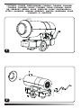
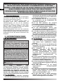
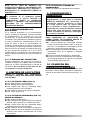
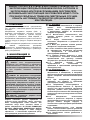
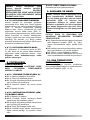
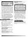
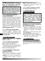
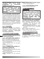
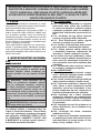
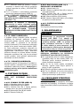
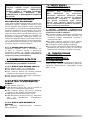
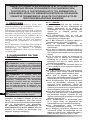
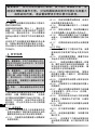
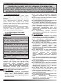
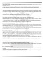
1. DESCRIPTION
This series of heaters is particularly suited to
heating medium to large-sized rooms or areas.
Thanks to a heat exchanger, indirect heaters
(PIC. 1) separate combustion gases from the
hot air released into the environment. This way
air in the area that needs to be heated up and
direct exhaust fumes outside.
These heaters have been designed in line with
the most recent safety, operating and duration
criteria. The safety devices ensure the machine
always operates correctly.
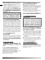
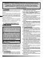
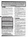
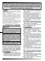
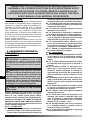
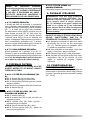
2. SAFETY INFORMATION
WARNINGS
IMPORTANT: This air heater has
been designed for mobile and temporary
professional applications. It has not been
designed for domestic use nor for thermal
comfort of human.
IMPORTANT: This appliance is not
-
by a person responsible for their safety.
headache, light-headedness and/or nausea.
These symptoms could be caused by the
-
-
be located in a separate facility or build-
ing.
-
mum distance from the heater, in accor-
-
neath dripping, or any other leakage
-
heater.
-
must be kept at a safe distance. It is ad-
-
-
ing fresh air from outdoors, in compli-
plate.
-
sion cable.
ecommended safety distanc-
-
stances are: front output = 2,5 m; side/
top/rear output = 1,5 m.
surface.
-
tance.

en
it
de
es
fr
nl
pt
da
no
sv
pl
ru
cs
hu
sl
tr
hr
lt
lv
et
ro
sk
bg
uk
bs
el
zh
the heater can turn on at any time.
used rooms or in bedrooms.
-
-
-
-
aged, it must be replaced by a technical
risks.
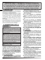
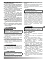
3. UNPACKING
WARNING: The packaging material is not
a toy. Keep the plastic bag out of the reach
3.1. Remove all packaging materials used
to wrap and deliver the heater and dispose
them in compliance with current regulations.
3.2. If the heater is placed on a moving
platform, make sure it is moved gently.
3.3. Check for any damage that might have
happened during transport. If the heater
looks damaged, immediately inform the
dealer from which it was purchased.
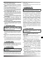
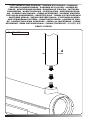
4. ASSEMBLY
and a chimney depending on the model (PIC.
2). These parts, which come with the relative
nuts and bolts, are in the heater’s packaging.
5. FUEL
DIESEL or KEROSENE.
use only diesel or kerosene fuel.
Never use petrol, naphtha, paint solvents, alco
-
Non-toxic, anti-freeze additives can be used in
case of very low temperatures.
It is advisable to use winter diesel below 5°C.
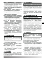
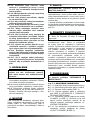
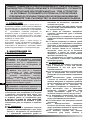
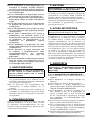
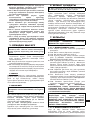
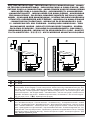
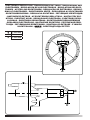
6. OPERATING PRINCIPLES
A. Combustion chamber and burner, B. Fan,
C. Motor, D. Pump, E. Tank, Chimney.
The pump draws fuel from the tank and brings
it to the operating pressure. The fuel is brought
to the nozzle that sprays it into the combustion
chamber. The combustion is carried out with a
is pushed outside via the rotation of the fan. In
with heated air. In indirect models combustion
products are directed outside through the
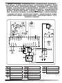
chimney. A series of sensors connected to an
electronic control board constantly keep the
correct operation of the heater monitored and
stops the cycle in the event of anomalies.
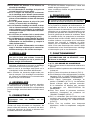
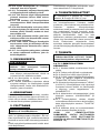
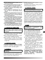
7. OPERATION
heater.
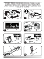
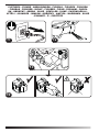
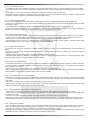
►►7.1. SWITCHING ON THE HEATER:
7.1.1. Follow all the safety instructions.
7.1.2. Check if there is any fuel in the tank.
7.1.3. Close the tank cap (FIG. 3).
7.1.4. Connect the power plug to the mains
(PIC. 4) (SEE VOLTAGE IN “TECHNICAL
DATA TABLE”).
7.1.5. Set the “ON/OFF” switch to “FLAME”
(A PIC. 5). The heater should turn on within a
few seconds. If the heater does not start, refer
to paragraph “12. “TROUBLESHOOTING”.
7.1.6. Maximum power is achieved by setting
the power switch to “DOUBLE FLAME” (B
PIC. 5).
7.1.7. The heater can be used in ventilation
mode, which is activated by setting the ON/
OFF switch to “FAN” (A PIC. 5).
7.1.8. For models with a room thermostat,
check the set temperature (PIC. 6).
IMPORTANT: In indirect models,
combustion products are directed outside

en
it
de
es
fr
nl
pt
da
no
sv
pl
ru
cs
hu
sl
tr
hr
lt
lv
et
ro
sk
bg
uk
bs
el
zh
►►7.2. RESETTING THE HEATER:
The appliance stops when an anomaly occurs.
The reset button turns on with a steady red light
(PIC. 7), it means the heater needs to be reset.
To reset the heater, press the reset button all
the way down (PIC. 8). Identify and remove
the cause that stopped the appliance (for
instance, obstruction of air intake and/or outlet,
total block of the fan, etc.). Please contact an
appointed service center for assistance in case
it is impossible to solve the problem.
►►7.3. SWITCHING OFF THE HEATER:
Set the “I/0” button to “0” (A PIC. 5). Flames
extinguish and the fan keeps on working until
the combustion chamber has fully cooled down.
Do not pull the plug out until the cooling
cycle has totally ended.
8. CLEANING THE FILTERS
►►8.1. FUEL TANK FILTER (PIC. 9):
8.1.1. Remove tank (A) cap.
8.1.2.
8.1.3.
without damaging it.
8.1.4.
8.1.5. Close cap (A).
►►8.2. INTAKE FILTER, (PIC. 10)
DEPENDING ON THE MODEL:
8.2.1. Remove the cup (A).
8.2.2.
Keep gaskets for later use.
8.2.3.
without damaging it.
8.2.4.
8.2.5. Put the glass (A) back on and
reassemble the gaskets correctly.
►►8.3. FUEL PUMP FILTER:
See the preventive maintenance schedule.
9. STORAGE AND TRANSPORT
during transport.
PROCEDURE:
9.1. Empty the fuel by removing the drain
cap at the bottom of the tank (PIC. 12).
Dispose the fuel in an appropriate container
in accordance with the current safety
regulations.
9.2. To remove any residual remaining, pour
clean fuel and rinse the tank again.
9.3. Close the drain cap and the tank cap.
9.4. In order to keep the heater in the best
possible conditions, we recommend placing
it in a dry and safe place.
10. CONNECTING THE ROOM
THERMOSTAT
In models with a thermostat connection,
remove the cap connected to the appliance
and connect the room thermostat (optional)
(SEE PIC. 13-14).

en
it
de
es
fr
nl
pt
da
no
sv
pl
ru
cs
hu
sl
tr
hr
lt
lv
et
ro
sk
bg
uk
bs
el
zh
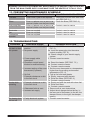
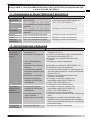
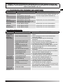
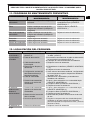
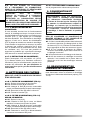
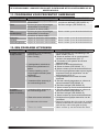
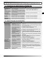
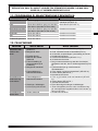
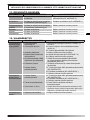
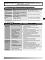
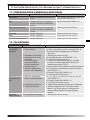
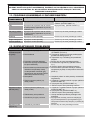
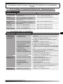
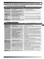
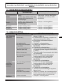
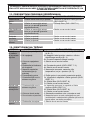
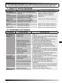
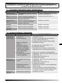
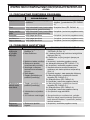
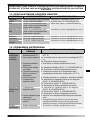
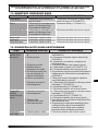
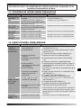
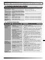
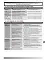
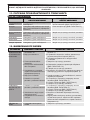
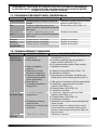
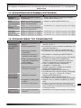
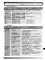
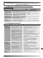
11. PREVENTIVE MAINTENANCE SCHEDULE
COMPONENT MAINTENANCE FREQUENCY MAINTENANCE PROCEDURE
Fuel tank Clean once a year or as required Empty and rinse the tank with clean
fuel (SEE PAR. 9.)
Filters Clean or replace once a year or as
required (make sure they are intact)
Clean or replace once a year or as
required (make sure they are intact)
Contact a service centre
Electrodes Clean as required Contact a service centre
Fan Clean as required Contact a service centre
Combustion
chamber
Clean as required Contact a service centre
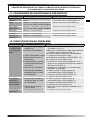
12. TROUBLESHOOTING
PROBLEM POSSIBLE CAUSE POSSIBLE SOLUTION
The heater does
not start or does
not operate
1. Starter switch in “OFF” (0)
position
2. No power supply
3. Power supply cable
interrupted
4. Electronic control board
blocked or malfunctioning
5. Incorrect setting of the room
thermostat (if present)
6. No fuel
7. External substances or dirt
in the fuel circuit
1. Set the “ON/OFF” switch to “FLAME” (A
PIC. 5)
2a. Insert the power plug into the mains
socket correctly (PIC. 4)
2b. Check voltage of your electric supply
system
3. Contact a service centre
4a. Reset the heater (SEE PAR. 7.2.)
4b. Contact a service centre
4c. Contact a service centre
5. Set the room thermostat to a temperature
higher than the working environment
temperature (PIC. 6)
6. Top up fuel and reset heater
7c. Contact a service centre
Smoke while
operating
1. External substances or dirt
in the fuel circuit
2. Obstructed inlet air vent
3. Incorrect air supply
1c. Contact a service centre
2. Remove all air vent obstructions
3. Adjust the air damper below the fan, in
the rear part of the heater (to the left, the
damper closes; to the right, the damper
opens)
The heater does
1. Faulty electronic system 1. Contact a service centre

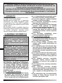
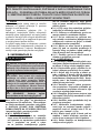
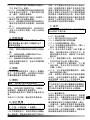
1. DESCRIZIONE
Questa serie di riscaldatori d’aria calda è partico-
larmente indicata per il riscaldamento di locali o
spazi, aventi medie o grandi dimensioni.
I riscaldatori a riscaldamento indiretto (FIG. 1)
grazie ad uno scambiatore di calore interno, per-
mettono di separare i gas di combustione dall’aria
calda immessa nell’ambiente. In questo modo è
possibile avere una corrente d’aria calda pulita nel
luogo da riscaldare e convogliare all’esterno i pro-
dotti della combustione.
Questi riscaldatori d’aria calda, sono stati pro-
gettati secondo i più moderni criteri di sicurezza,
funzionalità e durata. I dispositivi di sicurezza ga-
rantiscono sempre il corretto funzionamento del
riscaldatore.
2. INFORMAZIONI SULLA SI-
CUREZZA
AVVERTENZE
professionali mobili e temporanee. Non è
destinato all’uso domestico, né al comfort
termico delle persone.
mentali ridotte, o inesperte, a meno che non
-
-
non giochino con l’apparecchio.
carbonio può risultare fatale.
-
con cefalee, capogiri e/o nausea. Tali sintomi
difettoso del riscaldatore. NEL CASO SI PRE-
-
MEDIATAMENTE ALL’APERTO e far riparare il
2.1.
2.1.1. Il personale incaricato del rifornimen-
-
rifornimento sicuro dei riscaldatori.
2.1.2. Usare solamente il tipo di combustibi-
spegnere il riscaldatore, ed attendere che si
-
-
parata.
2.1.5. Tutti i serbatoi del combustibile, de-
-
-
-
l’accensione.
-
gente.
2.2.1. Non usare mai il riscaldatore in locali
2.2.2. Durante l’uso del riscaldatore, attener-
-
-
loni, tende o altri materiali simili di coper-
-
materiali di copertura di tipo ignifugo.
Predisporre un’apertura adeguata secondo
aria fresca dall’esterno.
2.2.5. Alimentare il riscaldatore solamente
2.2.6. Usare solamente prolunghe opportu-
namente collegate a massa.
-
sigliate, intercorrenti tra il riscaldatore e le
-
re = 2,5 m; di lato, in alto e sul retro = 1,5 m.
en
it
de
es
fr
nl
pt
da
no
sv
pl
ru
cs
hu
sl
tr
hr
lt
lv
et
ro
sk
bg
uk
bs
el
zh

2.2.8. Porre il riscaldatore caldo, o in fun-
-
2.2.10. Scollegare il riscaldatore dalla presa
di rete, quando non lo si usa.
-
stato, il riscaldatore può accendersi in qual-
siasi momento.
2.2.12. Non usare mai il riscaldatore in stan-
letto.
2.2.13. Non bloccare mai la presa dell’aria,
-
datore.
-
-
2.2.15.
.
-
-
de del riscaldatore.
-
ogni rischio.
3. DISIMBALLAGGIO
non è un giocattolo per bambini. Tenere il
sacchetto di plastica lontano dalla portata dei
3.1. Rimuovere tutti i materiali di imballaggio
usati per confezionare e spedire il riscaldatore.
Smaltirli secondo le norme vigenti.
3.2. Nel caso il riscaldatore fosse posto sulla
pedana, farlo scendere delicatamente.
3.3. Controllare eventuali danni subiti durante il
trasporto. Se il riscaldatore appare danneggia-
to, informare immediatamente il concessionario
presso il quale è stato acquistato.
4. ASSEMBLAGGIO
Questi riscaldatori sono dotati di ruote, maniglia, e
camino a seconda del modello (FIG. 2). Tali com-
ponenti, completi della relativa bulloneria di mon-
taggio, sono situati nell’imballo del riscaldatore.
5. COMBUSTIBILE
con DIESEL o KEROSENE.
Usare solamente diesel o kerosene, per evitare ri-
schi di incendio o di esplosione. Non fare mai uso
di benzina, nafta, solventi per vernici, alcool o altri
Usare additivi antigelo non tossici in caso di tem-
perature molto basse.
Si consiglia di utilizzare gasolio invernale al di
sotto dei 5°C.
6. PRINCIPI DI
FUNZIONAMENTO
A. Camera e testa combustione, B. Ventola, C.
Motore, D. Pompa, E. Serbatoio, Camino.
La pompa aspira il combustibile dal serbatoio
portandolo alla pressione di funzionamento.
Il combustibile viene portato all’ugello che lo
nebulizza nella camera di combustione. La
combustione avviene tramite una miscela di
aria/combustibile e i suoi prodotti vengono
dalla rotazione della ventola. Nei modelli diretti i
riscaldato, mentre nei modelli indiretti i prodotti
della combustione possono essere convogliati
all’esterno, dell’ambiente riscaldato, mediante
canalizzazione. Una serie di sensori, collegati
costantemente il corretto funzionamento del
riscaldatore, arrestando il ciclo in caso di anomalie.
7. FUNZIONAMENTO
“
di accendere il riscaldatore.
►►7.1. ACCENSIONE DEL
RISCALDATORE:
7.1.1. Seguire tutte le istruzioni relative alla
sicurezza.
7.1.2. Controllare la presenza di combustibile
nel serbatoio.
7.1.3. Chiudere il tappo del serbatoio (FIG. 3).
7.1.4. Collegare la spina di alimentazione alla
rete elettrica (FIG. 4) (VEDERE TENSIONE IN
“TABELLA DATI TECNICI”).
7.1.5. Portare l’interruttore di accensione in
posizione “FIAMMA” (A FIG. 5). Il riscaldatore
dovrebbe accendersi entro pochi secondi. Se il
riscaldatore non si avvia, consultare il paragrafo
“12. INDIVIDUAZIONE PROBLEMA”.
7.1.6. Per ottenere la massima potenza,
posizionare l’interruttore di potenza in posizione
“DOPPIA FIAMMA” (B FIG. 5).
en
it
de
es
fr
nl
pt
da
no
sv
pl
ru
cs
hu
sl
tr
hr
lt
lv
et
ro
sk
bg
uk
bs
el
zh

7.1.7. Il riscaldatore può essere utilizzato in
modalità ventilazione, per attivare tale funzione,
posizionare l’interruttore di accensione in
posizione “VENTOLA” (A FIG. 5).
7.1.8. Per i modelli con termostato ambiente,
N.B.: IN CASO DI SPEGNIMENTO DEL
RISCALDATORE DOVUTO ALL’ESAURIMENTO
DEL COMBUSTIBILE, RABBOCCARE IL
SERBATOIO E RESETTARE IL RISCALDATORE
IMPORTANTE: Nei modelli indiretti, i prodotti
SECONDO LA NORMATIVA VIGENTE E
7.2. RESET DEL RISCALDATORE:
funzionamento, il riscaldatore si spegne. Quando
il pulsante di reset si presenta acceso con luce
necessita di essere resettato. Per resettare il
riscaldatore premere a fondo il pulsante di reset
(FIG. 8). Prima di rimettere in funzione il riscaldatore,
si deve individuare ed eliminare la causa che ha
prodotto il blocco (ad esempio, ostruzione della
presa d’aria in entrata e/o di mandata dell’aria,
arresto del ventilatore, ecc.). Nel caso non si
riuscisse ad eliminare il problema che ha causato il
blocco, far intervenire il centro di assistenza tecnica.
7.3. SPEGNIMENTO DEL
RISCALDATORE:
Portare l’interruttore di accensione in posizione
“0” (A FIG. 5)
della camera di combustione. Non scollegare la
8. PULIZIA FILTRI
8.1. FILTRO DI CARICO (FIG. 9):
8.1.1. Rimuovere il tappo (A) del serbatoio.
8.1.2.
8.1.3.
facendo attenzione a non danneggiarlo.
8.1.4.
8.1.5. Chiudere il tappo (A).
8.2. FILTRO DI ASPIRAZIONE, (FIG.
10) A SECONDA DEL MODELLO:
8.2.1. Rimuovere il bicchiere (A).
8.2.2.
attenzione a conservare con cura le guarnizioni.
8.2.3.
facendo attenzione a non danneggiarlo.
8.2.4.
8.2.5. Rimontare il bicchiere (A) facendo attenzione
a rimontare correttamente le guarnizioni.
8.3. FILTRO POMPA COMBUSTIBILE:
Vedere programma manutenzione preventiva.
9. CONSERVAZIONE E
TRASPORTO
del riscaldatore e assicurasi che il tappo del
RISCALDATORE, SI CONSIGLIA DI SEGUIRE
LA PROCEDURA SEGUENTE:
9.1. Svuotare il serbatoio dal combustibile
rimuovendo il tappo di scarico posto sul fondo
del serbatoio (FIG. 12). Smaltire il combustibile
in modo appropriato e secondo le norme vigenti.
9.2. Se si nota la presenza di residui, versare
combustibile pulito nel serbatoio e scaricare
nuovamente.
9.3. Chiudere il tappo di scarico e del serbatoio.
9.4.
si consiglia di riporlo in un luogo asciutto e al
riparo da possibili danneggiamenti.
10. COLLEGAMENTO
TERMOSTATO AMBIENTE
Nei modelli con predisposizione collegamento ter-
mostato ambiente, rimuovere il tappo collegato al
riscaldatore e connettere il termostato ambiente
(optional) (FIG. 13-14).
en
it
de
es
fr
nl
pt
da
no
sv
pl
ru
cs
hu
sl
tr
hr
lt
lv
et
ro
sk
bg
uk
bs
el
zh

11. PROGRAMMA DI MANUTENZIONE PREVENTIVA
COMPONENTE FREQUENZA MANUTENZIONE PROCEDURA MANUTEZIONE
Serbatoio del
combustibile
Pulire una volta all’anno o a seconda
delle necessità
Svuotare e risciacquare il serbatoio con
combustibile pulito (VEDI PARAG. 9.)
Filtri Pulire o sostituire una volta all’anno o
l’integrità)
Filtro pompa
combustibile
Pulire o sostituire una volta all’anno o
l’integrità)
Rivolgersi al centro di assistenza
Elettrodi Pulire a seconda delle necessità Rivolgersi al centro di assistenza
Ventola Pulire a seconda delle necessità Rivolgersi al centro di assistenza
Camera di
combustione
Pulire a seconda delle necessità Rivolgersi al centro di assistenza
12. INDIVIDUAZIONE PROBLEMA
PROBLEMA POSSIBILE CAUSA POSSIBILE SOLUZIONE
Il riscaldatore
non si avvia
o non rimane
acceso
1. Interruttore di accensione
in posizione “0”
2. Mancanza alimentazione
3. Cavo di alimentazione
interrotto
4. Elettronica da resettare o
difettosa
5. Impostazione errata del
termostato ambiente (dove
presente)
6. Mancanza combustibile
7. Presenza di sostanze
estranee nel circuito del
combustibile
1. Portare l’interruttore di accensione in posizione
“FIAMMA” (A FIG. 5)
2a. Inserire correttamente il cavo di alimentazione
alla presa di rete elettrica (FIG. 4)
impianto
3. Rivolgersi al centro di assistenza
4a. Resettare il riscaldatore (VEDI PARAG. 7.2.)
4b. Rivolgersi al centro di assistenza
5. Agire sul termostato ambiente, impostandolo ad
una temperatura superiore a quella dell’ambiente
di lavoro (FIG. 6)
6. Rifornire combustibile ed eventualmente
resettare il riscaldatore
7a. Svuotare e riempire il serbatoio con
combustibile pulito (VEDI PARAG. 9.)
7c. Rivolgersi al centro di assistenza
Il riscaldatore
produce fumo
durante il
funzionamento
1. Presenza di sostanze
estranee nel circuito del
combustibile
2. Ostruzione della presa
d’aria in entrata
3. Apporto aria non corretto
1a. Svuotare e riempire il serbatoio con
combustibile pulito (VEDI PARAG. 9.)
1c. Rivolgersi al centro di assistenza
2. Rimuovere tutte le possibili ostruzioni della presa
d’aria
3. Regolare la serranda aria posizionata sotto il
ventilatore nella parte posteriore del riscaldatore
(verso sinistra la serranda si chiude, verso destra
la serranda si apre)
Il riscaldatore
non si spegne
1. Elettronica difettosa 1. Rivolgersi al centro di assistenza
en
it
de
es
fr
nl
pt
da
no
sv
pl
ru
cs
hu
sl
tr
hr
lt
lv
et
ro
sk
bg
uk
bs
el
zh

en
it
de
es
fr
nl
pt
da
no
sv
pl
ru
cs
hu
sl
tr
hr
lt
lv
et
ro
sk
bg
uk
bs
el
zh
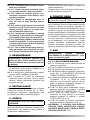
1. BESCHREIBUNG
Diese Serie von Heissluftgebläsen ist insbesondere
zum Heizen von Räumen oder Flächen mit mittleren
oder großen Abmessungen geeignet.
Die Heizgeräte mit indirekter Heizung (ABB. 1)
ermöglichen durch einen Wärmetauscher, die
Verbrennungsgase von der an die Umgebung
abgegebenen Heißluft zu trennen. Auf diese Weise
kann ein Strom sauberer Heißluft in den Raum
geblasen werden, der geheizt werden soll, während
die Abgase ins Freie abgeleitet werden.
Diese Heißluftgebläsen sind nach den modernsten
Sicherheitskriterien und mit modernsten Funktionen und
langer Haltbarkeit ausgelegt. Sicherheitsvorrichtungen
gewährleisten immer das korrekte Funktionieren des
Heizgeräts.
2. INFORMATIONEN ÜBER
DIE SICHERHEIT
HINWEISE
-
-
Die ersten Symptome einer
den geltenden Vorschriften einen mindesten
Entsprechend den geltenden Vorschriften für
oben und an der Rückseite = 1,5 m.

en
it
de
es
fr
nl
pt
da
no
sv
pl
ru
cs
hu
sl
tr
hr
lt
lv
et
ro
sk
bg
uk
bs
el
zh
Thermostat gesteuert ist, kann es sich in jede
beliebigen Moment einschalten.
daran keine Wartungsarbeiten durchgeführt
einhalten.
3. AUSPACKEN
3.1. Alle Verpackungsmaterialien, die zum Verpacken
und für den Versand des Heizgeräts benutzt wurden,
entfernen. Diese nach den geltenden Vorschriften
entsorgen.
3.2. Falls das Heizgerät auf einer Palette geliefert
wurde, es vorsichtig von dieser herunter heben.
3.3. Das Gerät auf eventuelle Transportschäden
überprüfen. Wenn das Heizgerät beschädigt
erscheint, sofort den Händler davon verständigen,
bei dem es gekauft wurde.
4. ZUSAMMENBAU
und einem Kamin ausgestattet (ABB. 2). Diese Bauteile
sind zusammen mit den zugehörigen Schrauben in der
Verpackung des Heizgeräts enthalten.
5. BRENNSTOFF
DIESEL oder mit KEROSIN.
Benutzen Sie nur Diesel oder Kerosin, um das Risiko
von Brand oder einer Explosion zu vermeiden. Niemals
Benzin, Lacklösungsmittel, Alkohol, oder andere hoch
Bei sehr niedrigen Temperaturen ungiftige
Frostschutzmittel verwenden.
Nur Winter Diesel Unter 5°C.
6. FUNKTIONSPRINZIPIEN
A. Brennkammer und Brenner, B. Lüfterrad, C.
Motor, D. Pumpe, E. Tank, . Schornsteinanschluss.
wird zur Düse befördert, die ihn in die Brennkammer
zerstäubt. Die Verbrennung erfolgt durch ein Luft-/
wird, nach außen befördert. Bei den direkten Modellen
enden die Verbrennungsprodukte in der geheizten
Umgebung, während die Verbrennungsprodukte bei
den indirekten Modellen durch eine Kanalisation nach
außerhalb des geheizten Raums geleitet werden
können. Eine Reihe von Sensoren, die an eine
elektronische Steuerkarte angeschlossen sind, prüfen
ständig den korrekten Betrieb des Heizgeräts und
stoppen den Zyklus im Fall von Anomalien.
7. BETRIEB
7.1. EINSCHALTEN DES HEIZGERÄTS:
7.1.1. Beachten Sie sämtliche Sicherheitshinweise.
7.1.2.
7.1.3. Schließen Sie den Tankdeckel (ABB. 3).
7.1.4. Netzstecker an das Stromnetz anschließen
(ABB. 4) (SIEHE SPANNUNG AUF DER „TABELLE
DER TECHNISCHEN DATEN“).
7.1.5. Den „EIN/AUS“-Schalter auf „FLAMME“ (A
ABB. 5) stellen. Das Heizgerät sollte sich innerhalb
weniger Sekunden einschalten. Wenn das
Heizgerät nicht startet, lesen Sie bitte Abschnitt
“12. FEHLERSUCHE”.
7.1.6. Für maximale Leistung stellen Sie den
Leistungsschalter auf die Position „DOPPELTE
FLAMME“ (B ABB. 5).
7.1.7. Das Heizgerät kann im Ventilationsmodus
verwendet werden, um diese Funktion zu aktivieren,
den „EIN/AUS“-Schalter auf die Position “Gebläse”
(A ABB. 5) stellen.
7.1.8. Für die Modelle mit Raumthermostat muss
die eingestellte Temperatur überprüft werden
(ABB. 6).

en
it
de
es
fr
nl
pt
da
no
sv
pl
ru
cs
hu
sl
tr
hr
lt
lv
et
ro
sk
bg
uk
bs
el
zh
7.2. ZURÜCKSETZEN DES
HEIZGERÄTS:
Wenn beim Normalbetrieb eine Anomalie auftritt,
schaltet das Heizgerät auf Blockade. Wenn der
Rücksetzschalter beständig rot leuchtet (ABB. 7)
bedeutet das, dass das Heizgerät zurückgesetzt
werden muss. Zum Zurücksetzen des Heizgeräts
die Reset-Taste ganz eindrücken (ABB. 8). Vor der
erneuten Inbetriebnahme des Heizgeräts muss
die Ursache, welche die Blockade hervorgerufen
hat, gefunden und behoben werden (z.B. verlegte
usw.). Falls das Problem, das die Blockade verursacht
hat, nicht gefunden werden kann, muss der
Kundendienst eingreifen.
7.3. AUSSCHALTEN DES HEIZGERÄTS:
Den Schalter „I/0“auf „0“ stellen (A ABB. 5). Die
Flamme geht aus und der Ventilator dreht sich so lang
weiter, bis die Brennkammer vollständig abgekühlt ist.
8. REINIGUNG DER FILTER
8.1. LADEFILTER (ABB. 9):
8.1.1. Den Tankdeckel (A) abnehmen.
8.1.2. Den Filter (B) aus dem Tank herausziehen.
8.1.3.
wobei darauf zu achten ist, ihn nicht zu beschädigen.
8.1.4. Den Filter (B) wieder in den Tank einsetzen.
8.1.5. Den Deckel (A) schließen.
8.2. ANSAUGFILTER (ABB. 10) JE NACH
MODELL:
8.2.1. Den Becher (A) entfernen.
8.2.2. Den Filter (B) aus dem Becher herausziehen,
wobei darauf zu achten ist, die Dichtungen sorgfältig
aufzubewahren.
8.2.3.
wobei darauf zu achten ist, ihn nicht zu beschädigen.
8.2.4. Den Filter (B) wieder in den Becher einsetzen.
8.2.5. Den Becher (A) wieder montieren, wobei
darauf zu achten ist, die Dichtungen wieder korrekt
anzubringen.
8.3. FILTER DER BRENNSTOFFPUMPE:
Siehe Programm für präventive Wartung.
9. AUFBEWAHRUNG UND
TRANSPORT
9.1.
gemäß den geltenden Vorschriften entsorgen.
9.2. Falls noch Rückstände bemerkt werden sollten,
ablassen.
9.3.
schließen.
9.4. Zur besten Aufbewahrung des Heizgeräts wird
angeraten, es an einen trockenen Ort zu bringen,
wo es vor äußeren Schäden geschützt ist.
10. ANSCHLIESSEN DES
RAUMTHERMOSTATS
Bei den Modellen mit einer Vorrichtung zum Anschließen
eines Thermostats den am Heizgerät angebrachten
Stöpsel entfernen und den Raumthermostat (Option)
anschließen (ABB. 13-14).

en
it
de
es
fr
nl
pt
da
no
sv
pl
ru
cs
hu
sl
tr
hr
lt
lv
et
ro
sk
bg
uk
bs
el
zh
11. PROGRAMM FÜR PRÄVENTIVE WARTUNG
BAUTEIL WARTUNGSHÄUFIGKEIT WARTUNGSPROZEDUR
Einmal jährlich oder je nach Bedarf
reinigen
Den Tank entleeren und mit sauberem
Filter Einmal jährlich oder je nach
Bedarf reinigen oder ersetzen (die
Unversehrtheit überprüfen)
Die Filter reinigen (SIEHE PARAGR. 8.)
Filter der
Einmal jährlich oder je nach
Bedarf reinigen oder ersetzen (die
Unversehrtheit überprüfen)
Wenden Sie sich an den Kundendienst
Elektroden Je nach Bedarf reinigen Wenden Sie sich an den Kundendienst
Lüfterrad Je nach Bedarf reinigen Wenden Sie sich an den Kundendienst
Brennkammer Je nach Bedarf reinigen Wenden Sie sich an den Kundendienst
12. FEHLERSUCHE
PROBLEM MÖGLICHE URSACHE MÖGLICHE LÖSUNG
Das Heizgerät
springt nicht
an oder
bleibt nicht
eingeschaltet
1. Hauptschalter auf Stellung „0“
2. Keine Stromversorgung
3. Stromkabel unterbrochen
4. Elektronik blockiert oder
defekt
5. Falsche Einstellung des
Raumthermostats (wenn
vorhanden)
7. Vorhandensein eines
Fremdkörpers in der
1. Den „EIN/AUS“-Schalter auf „FLAMME“ (A ABB. 5)
stellen
2a. Das Stromkabel korrekt an die Netzsteckdose
anstecken (ABB. 4)
2b. Die korrekte Spannung Ihrer Stromanlage
überprüfen
3. Wenden Sie sich an den Kundendienst
4a. Das Heizgerät rücksetzen (SIEHE PARAGR. 7.2.)
4b. Wenden Sie sich an den Kundendienst.
5. Den Raumthermostat so einstellen, dass er auf eine
höhere Temperatur als die der Arbeitsumgebung
eingestellt ist (ABB. 6)
rücksetzen
7a. Den Tank entleeren und dann wieder mit sauberem
7b. Die Filter reinigen (SIEHE PARAGR. 8.)
7c. Wenden Sie sich an den Kundendienst
Das Heizgerät
erzeugt beim
Betrieb Rauch
1. Vorhandensein eines
Fremdkörpers in der
verlegt
3. Luftzufuhr nicht korrekt
1a. Den Tank entleeren und dann wieder mit sauberem
1b. Die Filter reinigen (SIEHE PARAGR. 8.)
1c. Wenden Sie sich an den Kundendienst
2. Alle Gegenstände, die möglicherweise die
3. Den Luftschieber unter dem Gebläse im hinteren Teil
des Heizgerätes einstellen (nach links wird die Zufuhr
Das Heizgerät
schaltet sich
nicht aus
1. Elektronik defekt 1. Wenden Sie sich an den Kundendienst

en
it
de
es
fr
nl
pt
da
no
sv
pl
ru
cs
hu
sl
tr
hr
lt
lv
et
ro
sk
bg
uk
bs
el
zh
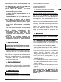
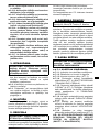
1. DESCRIPCIÓN
Esta serie de calefactores de aire caliente está
particularmente indicada para la calefacción
de locales o espacios de medianas o grandes
dimensiones.
Los calefactores de calefacción indirecta (FIG.
1), gracias a un intercambiador de calor, permiten
separar los gases de combustión de aire caliente
cedidos al ambiente. De este modo, es posible
introducir una corriente de aire caliente limpio en el
lugar que se debe calentar y transportar al exterior
los humos de descarga.
Estos calefactores de aire caliente han sido
diseñados según los criterios de seguridad,
funcionalidad y duración más modernos. Los
dispositivos de seguridad garantizan siempre el
correcto funcionamiento del calefactor.
2. INFORMACIÓN DE
SEGURIDAD
ADVERTENCIAS
IMPORTANTE: Este generador de aire
caliente ha sido diseñado para aplicaciones
sido diseñado para uso doméstico ni para el
bienestar térmico de las personas.
IMPORTANTE: Este aparato no es apto
de una persona responsable por su seguridad.
Se debe controlar a los niños para asegurarse
de que no jueguen con el aparato.
puede ser mortal.
carbono se asemejan a los de la gripe, con cefale
-
ser ocasionados por el funcionamiento defec-
tuoso del calefactor. SI SE PRESENTAN ESTOS
SÍNTOMAS, SALGA INMEDIATAMENTE AL AIRE
LIBRE y haga reparar el calefactor por el centro
de asistencia técnica.
2.1. ABASTECIMIENTO:
materia del abastecimiento seguro de los
calefactores.
apague el calefactor y espere hasta que se
de carburante deben encontrarse en una
estructura separada.
deben encontrarse a una distancia de
locales cuyo suelo no permita la penetración
y el goteo de dicho combustible sobre
llamas subyacentes, capaces de ocasionar el
encendido de estas.
2.2. SEGURIDAD:
similares de cobertura, deben estar situados
a una distancia de seguridad de dichos
con corriente con la tensión y la frecuencia
adecuadamente conectadas a masa.
aconsejadas entre el calefactor y las sustancias
arriba y posterior = 1,5 m.

en
it
de
es
fr
nl
pt
da
no
sv
pl
ru
cs
hu
sl
tr
hr
lt
lv
et
ro
sk
bg
uk
bs
el
zh
de seguridad del calefactor.
desconéctelo de la toma de red.
cualquier momento cuando esté controlado
por un termostato.
habitaciones frecuentemente habitadas ni en
dormitorios.
conectado a la red eléctrica o en funcionamiento,
mantenimiento sobre este.
calientes del calefactor.
dañado, deberá ser sustituido por el centro de
riesgos.
3. DESEMBALAJE
ADVERTENCIA: El material de embalaje no es
un juguete para los niños. Mantenga la bolsa
de plástico alejada del alcance de los niños,
3.1. Retire todo el material de embalaje utilizado
para envolver y enviar el calefactor. Elimínelo
según las normas vigentes.
3.2. Si el calefactor estuviera situado sobre una
plataforma, bájelo con delicadeza.
3.3. Controle los eventuales daños ocasionados
durante el transporte. Si el calefactor estuviera
dañado, informe inmediatamente al concesionario
al cual se lo ha comprado.
4. ENSAMBLAJE
Estos calefactores están equipados con ruedas,
manija y conducto de humos, según el modelo (FIG.
2). Estos componentes, equipados con la tornillería
de montaje correspondiente, se encuentran en el
embalaje del calefactor.
5. COMBUSTIBLE
ADVERTENCIA: El calefactor funciona
Use únicamente diésel o queroseno, para evitar
riesgos de incendio o de explosión. Nunca utilice
bencina, nafta, disolventes para pinturas, alcohol u
Use aditivos anticongelantes no tóxicos en caso de
temperaturas muy bajas.
Se aconseja utilizar gasóleo invernal por debajo de
los 5°C.
6. PRINCIPIOS DE
FUNCIONAMIENTO
A. Cámara y cabeza de combustión, B. Ventilador,
C. Motor, D. Bomba, E. Depósito, Conducto de
humos.
La bomba aspira el combustible del depósito
llevándolo a la presión de funcionamiento. El
combustible es llevado a la boquilla que lo nebuliza
en la cámara de combustión. La combustión se
produce mediante una mezcla de aire/combustible y
sus productos son impulsados al exterior mediante el
los modelos directos los productos de la combustión
terminan en el ambiente calentado; mientras que
en los modelos indirectos los productos de la
combustión pueden ser transportados al exterior del
ambiente calentado mediante una canalización.
Una serie de sensores, conectados a una tarjeta
correcto funcionamiento del calefactor, deteniendo
el ciclo en el caso de anomalías.
7. FUNCIONAMIENTO
ADVERTENCIA: Lea atentamente la
encender el calefactor.
►►7.1. ENCENDIDO DEL CALEFACTOR:
7.1.1. Siga todas las instrucciones relativas a la
seguridad.
7.1.2. Controle la presencia de combustible en el
depósito.
7.1.3. Cierre el tapón del depósito (FIG. 3).
7.1.4. Conecte la clavija de alimentación a la red
eléctrica (FIG. 4) (VÉASE LA TENSIÓN EN LA
“TABLA DE DATOS TÉCNICOS”).
7.1.5. Coloque el interruptor de encendido en
posición “LLAMA” (A FIG. 5). El calentador
debería encenderse pocos segundos después. Si
el calefactor no se pone en marcha, consulte el
apartado “12. LOCALIZACIÓN DEL PROBLEMA”.
7.1.6. Para obtener la máxima potencia colocar
el interruptor de potencia en la posición “DOBLE
LLAMA” (B FIG. 5).
7.1.7. El calentador puede usarse en modo
ventilador, para activar esta función coloque
el interruptor de encendido en la posición
VENTILADOR” (A FIG. 5).
7.1.8. Para los modelos con termostato ambiente,
Pagina se încarcă...
Pagina se încarcă...
Pagina se încarcă...
Pagina se încarcă...
Pagina se încarcă...
Pagina se încarcă...
Pagina se încarcă...
Pagina se încarcă...
Pagina se încarcă...
Pagina se încarcă...
Pagina se încarcă...
Pagina se încarcă...
Pagina se încarcă...
Pagina se încarcă...
Pagina se încarcă...
Pagina se încarcă...
Pagina se încarcă...
Pagina se încarcă...
Pagina se încarcă...
Pagina se încarcă...
Pagina se încarcă...
Pagina se încarcă...
Pagina se încarcă...
Pagina se încarcă...
Pagina se încarcă...
Pagina se încarcă...
Pagina se încarcă...
Pagina se încarcă...
Pagina se încarcă...
Pagina se încarcă...
Pagina se încarcă...
Pagina se încarcă...
Pagina se încarcă...
Pagina se încarcă...
Pagina se încarcă...
Pagina se încarcă...
Pagina se încarcă...
Pagina se încarcă...
Pagina se încarcă...
Pagina se încarcă...
Pagina se încarcă...
Pagina se încarcă...
Pagina se încarcă...
Pagina se încarcă...
Pagina se încarcă...
Pagina se încarcă...
Pagina se încarcă...
Pagina se încarcă...
Pagina se încarcă...
Pagina se încarcă...
Pagina se încarcă...
Pagina se încarcă...
Pagina se încarcă...
Pagina se încarcă...
Pagina se încarcă...
Pagina se încarcă...
Pagina se încarcă...
Pagina se încarcă...
Pagina se încarcă...
Pagina se încarcă...
Pagina se încarcă...
Pagina se încarcă...
Pagina se încarcă...
Pagina se încarcă...
Pagina se încarcă...
Pagina se încarcă...
Pagina se încarcă...
Pagina se încarcă...
Pagina se încarcă...
Pagina se încarcă...
Pagina se încarcă...
Pagina se încarcă...
Pagina se încarcă...
Pagina se încarcă...
Pagina se încarcă...
Pagina se încarcă...
Pagina se încarcă...
Pagina se încarcă...
Pagina se încarcă...
Pagina se încarcă...
Pagina se încarcă...
Pagina se încarcă...
Pagina se încarcă...
Pagina se încarcă...
Pagina se încarcă...
Pagina se încarcă...
Pagina se încarcă...
Pagina se încarcă...
Pagina se încarcă...
Pagina se încarcă...
Pagina se încarcă...
Pagina se încarcă...
Pagina se încarcă...
Pagina se încarcă...
Pagina se încarcă...
Pagina se încarcă...
Pagina se încarcă...
Pagina se încarcă...
Pagina se încarcă...
Pagina se încarcă...
Pagina se încarcă...
Pagina se încarcă...
Pagina se încarcă...
Pagina se încarcă...
Pagina se încarcă...
Pagina se încarcă...
Pagina se încarcă...
Pagina se încarcă...
Pagina se încarcă...
Pagina se încarcă...
Pagina se încarcă...
Pagina se încarcă...
Pagina se încarcă...
-
 1
1
-
 2
2
-
 3
3
-
 4
4
-
 5
5
-
 6
6
-
 7
7
-
 8
8
-
 9
9
-
 10
10
-
 11
11
-
 12
12
-
 13
13
-
 14
14
-
 15
15
-
 16
16
-
 17
17
-
 18
18
-
 19
19
-
 20
20
-
 21
21
-
 22
22
-
 23
23
-
 24
24
-
 25
25
-
 26
26
-
 27
27
-
 28
28
-
 29
29
-
 30
30
-
 31
31
-
 32
32
-
 33
33
-
 34
34
-
 35
35
-
 36
36
-
 37
37
-
 38
38
-
 39
39
-
 40
40
-
 41
41
-
 42
42
-
 43
43
-
 44
44
-
 45
45
-
 46
46
-
 47
47
-
 48
48
-
 49
49
-
 50
50
-
 51
51
-
 52
52
-
 53
53
-
 54
54
-
 55
55
-
 56
56
-
 57
57
-
 58
58
-
 59
59
-
 60
60
-
 61
61
-
 62
62
-
 63
63
-
 64
64
-
 65
65
-
 66
66
-
 67
67
-
 68
68
-
 69
69
-
 70
70
-
 71
71
-
 72
72
-
 73
73
-
 74
74
-
 75
75
-
 76
76
-
 77
77
-
 78
78
-
 79
79
-
 80
80
-
 81
81
-
 82
82
-
 83
83
-
 84
84
-
 85
85
-
 86
86
-
 87
87
-
 88
88
-
 89
89
-
 90
90
-
 91
91
-
 92
92
-
 93
93
-
 94
94
-
 95
95
-
 96
96
-
 97
97
-
 98
98
-
 99
99
-
 100
100
-
 101
101
-
 102
102
-
 103
103
-
 104
104
-
 105
105
-
 106
106
-
 107
107
-
 108
108
-
 109
109
-
 110
110
-
 111
111
-
 112
112
-
 113
113
-
 114
114
-
 115
115
-
 116
116
-
 117
117
-
 118
118
-
 119
119
-
 120
120
-
 121
121
-
 122
122
-
 123
123
-
 124
124
-
 125
125
-
 126
126
-
 127
127
-
 128
128
-
 129
129
-
 130
130
-
 131
131
-
 132
132
-
 133
133


Master BV 400 4035.188 E19R2 Manualul proprietarului
- Categorie
- Incalzitoare de spatiu
- Tip
- Manualul proprietarului
Lucrări înrudite
-
Master XL91 4117.725 E19R05 Manualul proprietarului
-
-
-
Master BV 471S Manual de utilizare
-
-
MCS Master RS 40 Manualul proprietarului
-
-
MCS Master DC 61 Manualul proprietarului
-
-
