Makita DLS714 Manual de utilizare
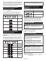
- Categorie
- Ferăstraie mitre
- Tip
- Manual de utilizare

DLS714
EN
Cordless Slide Compound
Miter Saw
INSTRUCTION MANUAL 11
SL
Brezžična drsna sestavljena
zajeralna žaga
NAVODILA ZA UPORABO 25
SQ
Sharrë me bateri për prerje me
kënd për prole me rrëshqitje
MANUALI I PËRDORIMIT 39
BG
Акумулаторен циркуляр за
рязане под ъгъл
РЪКОВОДСТВО ЗА
ЕКСПЛОАТАЦИЯ
54
HR
Bežična potezno-nagibna pila PRIRUČNIK S UPUTAMA 71
МК
Безжична потезна
комбинирана аголна пила
УПАТСТВО ЗА УПОТРЕБА 85
SR
Бежична клизна
комбинована угаона тестера
УПУТСТВО ЗА УПОТРЕБУ 101
RO
Ferăstrău pentru tăieri oblice
combinate, fără cablu
MANUAL DE INSTRUCŢIUNI 117
UK
Акумуляторна пересувна
комбінована пила для
різання під кутом
ІНСТРУКЦІЯ З
ЕКСПЛУАТАЦІЇ
132
RU
Аккумуляторная торцовочная
пила консольного типа
РУКОВОДСТВО ПО
ЭКСПЛУАТАЦИИ
148

1
3
2
4
5
6
7
8
9
10
11
12
12
13
14
15
16
18
17
Fig.1
19
20
21
22
23
24
25
22
Fig.2
1
1
Fig.3
1
Fig.4
2

2
2
1
3
Fig.5
1
2
1
Fig.6
1
2
Fig.7
1
Fig.8
1
Fig.9
1
2
Fig.10
1
Fig.11
1
Fig.12
3

1
2
2
Fig.13
1
1
Fig.14
Fig.15
1 1
3
45
3
2 2
Fig.16
1
2
Fig.17
Fig.18
Fig.19
4

1
2
Fig.20
1
Fig.21
1
2
3
4
5
Fig.22
1
2
Fig.23
1
2
3
Fig.24
2
1
Fig.25
1
2
4
3
Fig.26
2
1
3
Fig.27
5

1
2
Fig.28
1
Fig.29
4
2
3
1
Fig.30
1
2
3
Fig.31
1
2
3
4
5
6
Fig.32
1
2
2
Fig.33
1
2
3
4
5
Fig.34
1
2
3
4
6
5
Fig.35
6

1
2
3
4
5
6
Fig.36
1
2
3
Fig.37
1
2
Fig.38
2
8
4
5
3
1
6
7
7
8
Fig.39
1
2
3
4
Fig.40
1
2
Fig.41
2
1
Fig.42
Fig.43
7

Fig.44
Fig.45
123
Fig.46
(a) (b) (c) (d)
12
Fig.47
2
(a)
(b)
(a)
(b)
(b)
(a)
(b)
(a)
(a)
(b)
(c)
(d)
1
Fig.48
2
3
1
4
Fig.49
(a) (b) (c) (d)
12
Fig.50
1
2
3
4
5
Fig.51
8

1
2
3
Fig.53
1
Fig.54
Fig.55
1
2
Fig.56
1
Fig.57
1
2
3
Fig.58
2
1
5
4
3
Fig.59
1
2
3
Fig.60
9

1
2
3
Fig.61
1
Fig.62
10

11 ENGLISH
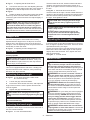
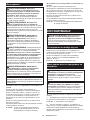
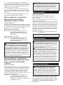
ENGLISH (Original instructions)
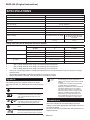
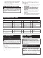
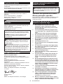
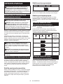
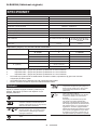
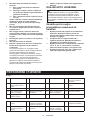
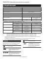
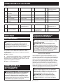
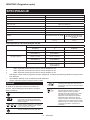
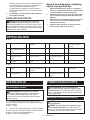
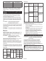
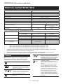
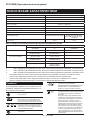
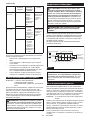
SPECIFICATIONS
Model: DLS714
Blade diameter 190 mm
Blade body thickness 1.3 mm - 2.0 mm
Hole (arbor) diameter (country specic) 20 mm or 15.88 mm
Max. miter angle Left 47°, Right 57°
Max. bevel angle Left 45°, Right 5°
No load speed 5,700 min
-1
Dimensions (L x W x H) 655 mm x 430 mm x 445 mm
Rated voltage D.C.36 V
Battery cartridge BL1815N, BL1820, BL1820B BL1830, BL1830B, BL1840,
BL1840B, BL1850, BL1850B,
BL1860B
Net weight 13.0 kg 13.5 kg
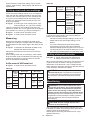
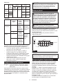
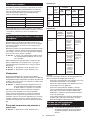
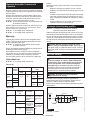
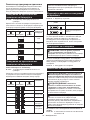
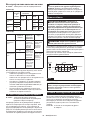
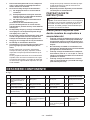
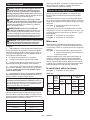
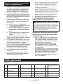
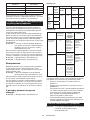
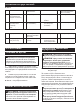
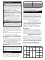
Cutting capacities (H x W) with blade 190 mm in diameter
Miter angle Bevel angle
45° (left) 0° 5° (right)
0° 40 mm x 300 mm 52 mm x 300 mm 40 mm x 300 mm
45 mm x 265 mm (NOTE 1) 60 mm x 265 mm (NOTE 1) –
45° (left and right) 40 mm x 212 mm 52 mm x 212 mm –
45 mm x 185 mm (NOTE 2) 60 mm x 185 mm (NOTE 2) –
57° (right) – 52 mm x 163 mm –
– 60 mm x 145 mm (NOTE 3) –
1. Max. Cutting capacity when using a wood facing 20 mm thickness
2. Max. Cutting capacity when using a wood facing 15 mm thickness
3. Max. Cutting capacity when using a wood facing 10 mm thickness
• Due to our continuing program of research and development, the specications herein are subject to change
without notice.
• Specications and battery cartridge may differ from country to country.
• Weight, with battery cartridge, according to EPTA-Procedure 01/2003
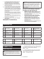
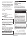
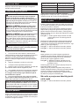
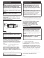
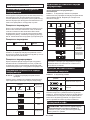
Symbols
The following show the symbols used for the equip-
ment. Be sure that you understand their meaning before
use.
Read instruction manual.
To avoid injury from ying debris, keep
holding the saw head down, after making
cuts, until the blade has come to a com-
plete stop.
When performing slide cut, rst pull car-
riage fully and press down handle, then
push carriage toward the guide fence.
Do not place hand or ngers close to the
blade.
Always set SUB-FENCE to left position
when performing left bevel cuts. Failure to
do so may cause serious injury to operator.
Cd
Ni-MH
Li-ion
Only for EU countries
Do not dispose of electric equipment or
battery pack together with household waste
material!
In observance of the European Directives,
on Waste Electric and Electronic
Equipment and Batteries and Accumulators
and Waste Batteries and Accumulators
and their implementation in accordance
with national laws, electric equipment and
batteries and battery pack(s) that have
reached the end of their life must be col-
lected separately and returned to an envi-
ronmentally compatible recycling facility.
Intended use
The tool is intended for accurate straight and miter
cutting in wood. With appropriate saw blades, aluminum
can also be sawed.
Do not use the saw to cut other than wood, aluminum or
similar materials.

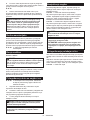
12 ENGLISH
Noise
The typical A-weighted noise level determined accord-
ing to EN61029:
Sound pressure level (L
pA
) : 88 dB(A)
Sound power level (L
WA
) : 97 dB (A)
Uncertainty (K) : 3 dB(A)
WARNING: Wear ear protection.
Vibration
The vibration total value (tri-axial vector sum) deter-
mined according to EN61029:
Vibration emission (a
h
) : 2.5 m/s
2
or less
Uncertainty (K) : 1.5 m/s
2
NOTE: The declared vibration emission value has
been measured in accordance with the standard test
method and may be used for comparing one tool with
another.
NOTE: The declared vibration emission value
may also be used in a preliminary assessment of
exposure.
WARNING: The vibration emission during actual
use of the power tool can differ from the declared
emission value depending on the ways in which the
tool is used.
WARNING: Be sure to identify safety measures
to protect the operator that are based on an estima-
tion of exposure in the actual conditions of use (taking
account of all parts of the operating cycle such as
the times when the tool is switched off and when it is
running idle in addition to the trigger time).
EC Declaration of Conformity
For European countries only
Makita declares that the following Machine(s):
Designation of Machine: Cordless Slide Compound
Miter Saw
Model No./ Type: DLS714
Conforms to the following European Directives:
2006/42/EC
They are manufactured in accordance with the following
standard or standardized documents: EN61029
The technical le in accordance with 2006/42/EC is
available from:
Makita, Jan-Baptist Vinkstraat 2, 3070, Belgium
16.1.2015
Yasushi Fukaya
Director
Makita, Jan-Baptist Vinkstraat 2, 3070, Belgium
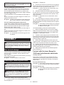
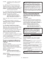
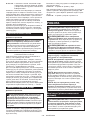
General power tool safety warnings
WARNING: Read all safety warnings and
all instructions. Failure to follow the warnings and
instructions may result in electric shock, re and/or
serious injury.
Save all warnings and instruc-
tions for future reference.
The term "power tool" in the warnings refers to your
mains-operated (corded) power tool or battery-operated
(cordless) power tool.
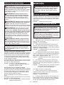
Cordless miter saw safety warnings
1. Keep hands out of path of saw blade. Avoid
contact with any coasting blade. It can still
cause severe injury.
2. Check the saw blade carefully for cracks or
deformation before operation.
Replace damaged blades immediately.
3. Replace the kerf board when worn.
4. Use only saw blades specied by the manufac-
turer which conform to EN847-1.
5. Do not use saw blades manufactured from
high speed steel.
6. Wear eye protection.
7. Wear hearing protection to reduce the risk of
hearing loss.
8. Wear gloves for handling saw blade (saw
blades shall be carried in a holder wherever
practicable) and rough material.
9. Connect miter saws to a dust collecting device
when sawing.
10. Select saw blades in relation to the material to
be cut.
11. Always secure all moving portions before car-
rying the tool. When lifting or carrying the tool,
do not use the guard as a carrying handle.
12. Do not operate saw without guards in place.
Check blade guard for proper closing before
each use. Do not operate saw if blade guard
does not move freely and close instantly.
Never clamp or tie the blade guard into the
open position.
13. Keep the oor area free of loose material e.g.
chips and cut-offs.
14. Use only saw blades that are marked with a
maximum speed equal to or higher than the no
load speed marked on the tool.
15. When the tool is tted with a laser or LED, do
not replace the laser or LED with a different
type. Ask an authorized service center for repair.
16. Never remove any cut-offs or other parts of the
workpiece from the cutting area whilst the tool
is running with an unguarded saw blade.
17. Do not perform any operation freehand. The
workpiece must be secured rmly against the
turn base and guide fence with the vise during all
operations. Never use your hand to secure the
workpiece.
18. Ensure that the tool is stable before each cut.
19. Fix the tool to a work bench, if needed.
20. Support long workpieces with appropriate
additional supports.
21. Never cut so small workpiece which cannot be
securely held by the vise. Improperly held work-
piece may cause kickback and serious personal
injury.
22. Never reach around saw blade.

13 ENGLISH
23. Turn off tool and wait for saw blade to stop
before moving workpiece or changing
settings.
24. Disconnect the plug from the power source
and/or the battery pack from the power tool
before changing blade or servicing.
25. Stopper pin which locks the cutter head down
is for carrying and storage purposes only and
not for any cutting operations.
26. Do not use the tool in the presence of amma-
ble liquids or gases. The electrical operation of
the tool could create an explosion and re when
exposed to ammable liquids or gases.
27. Use only anges specied for this tool.
28. Be careful not to damage the arbor, anges
(especially the installing surface) or bolt.
Damage to these parts could result in blade
breakage.
29. Make sure that the turn base is properly
secured so it will not move during operation.
30. For your safety, remove the chips, small
pieces, etc. from the table top before
operation.
31. Avoid cutting nails. Inspect for and remove all
nails from the workpiece before operation.
32. Make sure the shaft lock is released before the
switch is turned on.
33. Be sure that the blade does not contact the
turn base in the lowest position.
34. Hold the handle rmly. Be aware that the saw
moves up or down slightly during start-up and
stopping.
35. Make sure the blade is not contacting the
workpiece before the switch is turned on.
36. Before using the tool on an actual workpiece,
let it run for a while. Watch for vibration or
wobbling that could indicate poor installation
or a poorly balanced blade.
37. Wait until the blade attains full speed before
cutting.
38. Stop operation immediately if you notice any-
thing abnormal.
39. Do not attempt to lock the trigger in the on
position.
40. Be alert at all times, especially during repeti-
tive, monotonous operations. Do not be lulled
into a false sense of security. Blades are
extremely unforgiving.
41. Always use accessories recommended in this
manual. Use of improper accessories such as
abrasive wheels may cause an injury.
42. Take care when slotting.
43. Some dust created from operation contains
chemicals known to cause cancer, birth
defects or other reproductive harm. Some
examples of these chemicals are:
• lead from lead-based-painted material
and,
• arsenic and chromium from chemical-
ly-treated lumber.
Your risk from these exposures varies,
depending on how often you do this type
of work. To reduce your exposure to these
chemicals: work in a well ventilated area and
work with approved safety equipment, such as
those dust masks that are specially designed
to lter out microscopic particles.
44. To reduce the emitted noise, always be sure
that the blade is sharp and clean.
45. The operator is adequately trained in the use,
adjustment and operation of the machine.
SAVE THESE INSTRUCTIONS.
WARNING: DO NOT let comfort or familiarity
with product (gained from repeated use) replace
strict adherence to safety rules for the subject
product. MISUSE or failure to follow the safety
rules stated in this instruction manual may cause
serious personal injury.
Important safety instructions for
battery cartridge
1.
Before using battery cartridge, read all instruc-
tions and cautionary markings on (1) battery
charger, (2) battery, and (3) product using battery.
2. Do not disassemble battery cartridge.
3. If operating time has become excessively
shorter, stop operating immediately. It may
result in a risk of overheating, possible burns
and even an explosion.
4. If electrolyte gets into your eyes, rinse them
out with clear water and seek medical atten-
tion right away. It may result in loss of your
eyesight.
5. Do not short the battery cartridge:
(1) Do not touch the terminals with any con-
ductive material.
(2) Avoid storing battery cartridge in a con-
tainer with other metal objects such as
nails, coins, etc.
(3) Do not expose battery cartridge to water
or rain.
A battery short can cause a large current
ow, overheating, possible burns and even a
breakdown.
6. Do not store the tool and battery cartridge in
locations where the temperature may reach or
exceed 50 °C (122 °F).
7. Do not incinerate the battery cartridge even if
it is severely damaged or is completely worn
out. The battery cartridge can explode in a re.
8. Be careful not to drop or strike battery.
9. Do not use a damaged battery.
10. The contained lithium-ion batteries are subject
to the Dangerous Goods Legislation require-
ments.
For commercial transports e.g. by third parties,
forwarding agents, special requirement on pack-
aging and labeling must be observed.
For preparation of the item being shipped, consult-
ing an expert for hazardous material is required.
Please also observe possibly more detailed
national regulations.

14 ENGLISH
Tape or mask off open contacts and pack up the
battery in such a manner that it cannot move
around in the packaging.
11. Follow your local regulations relating to dis-
posal of battery.
SAVE THESE INSTRUCTIONS.
CAUTION: Only use genuine Makita batteries.
Use of non-genuine Makita batteries, or batteries that
have been altered, may result in the battery bursting
causing res, personal injury and damage. It will
also void the Makita warranty for the Makita tool and
charger.
Tips for maintaining maximum
battery life
1. Charge the battery cartridge before completely
discharged. Always stop tool operation and
charge the battery cartridge when you notice
less tool power.
2. Never recharge a fully charged battery car-
tridge. Overcharging shortens the battery
service life.
3. Charge the battery cartridge with room tem-
perature at 10 °C - 40 °C (50 °F - 104 °F). Let
a hot battery cartridge cool down before
charging it.
4. Charge the battery cartridge if you do not use
it for a long period (more than six months).
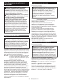
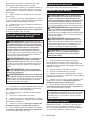
PARTS DESCRIPTION
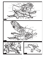
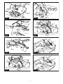
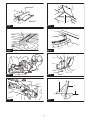
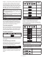
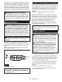
► Fig.1
1 Lock-off button 2 Switch trigger 3 Blade case 4 Adjusting screw (for
lower limit position)
5 Adjusting bolt (for maxi-
mum cutting capacity)
6 Stopper arm 7 Dust bag 8 Bevel scale
9 Blade guard 10 Vertical vice 11 Guide fence 12 Holder
13 Lock lever (for turn base) 14 Grip (for turn base) 15 Adjusting bolt (for turn
base)
16 Kerf board
17 Pointer (for miter angle) 18 Turn base - - - -
► Fig.2
19 Slide pole (upper) 20 Thumb screw (for lock-
ing upper slide pole)
21 Hex wrench 22 Clamp screw (for locking
holder)
23 Lever (for bevel angle
adjustment)
24 Slide pole (lower) 25 Thumb screw (for lock-
ing lower slide pole)
- -
INSTALLATION
Bench mounting
WARNING: Ensure that the tool does not
move on the supporting surface. Movement of the
miter saw on the supporting surface while cutting may
result in loss of control and serious personal injury.
1. Fix the base to a level and stable surface, screw-
ing with two bolts. This helps to prevent from tipping and
possible injury.
► Fig.3: 1. Bolt
2. Turn the adjusting bolt clockwise or counterclock-
wise so that it comes into a contact with the oor sur-
face to keep the tool stable.
► Fig.4: 1. Adjusting bolt
FUNCTIONAL
DESCRIPTION
WARNING: Always be sure that the tool is
switched off and the battery cartridge is removed
before adjusting or checking the functions on
the tool. Failure to switch off and remove the battery
cartridge may result in serious personal injury from
accidental start-up.
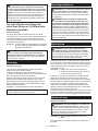
Installing or removing battery
cartridge
CAUTION: Always switch off the tool before
installing or removing of the battery cartridge.
CAUTION:
Hold the tool and the battery cartridge
rmly when installing or removing battery cartridge.
Failure to hold the tool and the battery cartridge rmly may
cause them to slip off your hands and result in damage to
the tool and battery cartridge and a personal injury.

15 ENGLISH
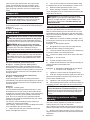
► Fig.5: 1. Red indicator 2. Button 3. Battery cartridge
To remove the battery cartridge, slide it from the tool
while sliding the button on the front of the cartridge.
To install the battery cartridge, align the tongue on the
battery cartridge with the groove in the housing and slip
it into place. Insert it all the way until it locks in place
with a little click. If you can see the red indicator on the
upper side of the button, it is not locked completely.
CAUTION: Always install the battery cartridge
fully until the red indicator cannot be seen. If not,
it may accidentally fall out of the tool, causing injury to
you or someone around you.
CAUTION: Do not install the battery cartridge
forcibly. If the cartridge does not slide in easily, it is
not being inserted correctly.
NOTE: The tool does not work with only one battery
cartridge.
Tool / battery protection system
The tool is equipped with a tool/battery protection sys-
tem. This system automatically cuts off power to the
motor to extend tool and battery life. The tool will auto-
matically stop during operation if the tool or battery is
placed under one of the following conditions:
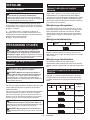
Overload protection
When the tool is operated in a manner that causes it to
draw an abnormally high current, the tool automatically
stops without any indication. In this situation, turn the
tool off and stop the application that caused the tool to
become overloaded. Then turn the tool on to restart.
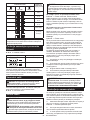
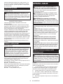
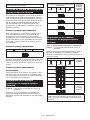
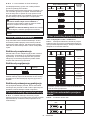
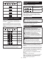
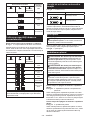
Overheat protection
on Blinking
When the tool is overheated, the tool stops automati-
cally, and the battery indicator blink about 60 seconds.
In this situation, let the tool cool down before turning the
tool on again.
Overdischarge protection
When the battery capacity becomes low, the tool stops
automatically. If the product does not operate even
when the switches are operated, remove the batteries
from the tool and charge the batteries.
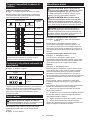
Indicating the remaining battery
capacity
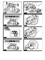
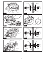
► Fig.6: 1. Battery indicator 2. Check button
Press the check button to indicate the remaining battery
capacities. The battery indicators correspond to each
battery.
Battery indicator status Remaining
battery
capacity
On
Off
Blinking
50% to 100%
20% to 50%
0% to 20%
Charge the
battery
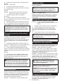
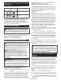
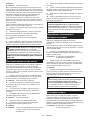
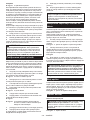
Indicating the remaining battery
capacity
Only for battery cartridges with the indicator
► Fig.7: 1. Indicator lamps 2. Check button
Press the check button on the battery cartridge to indi-
cate the remaining battery capacity. The indicator lamps
light up for few seconds.
Indicator lamps Remaining
capacity
Lighted Off Blinking
75% to 100%
50% to 75%
25% to 50%
0% to 25%
Charge the
battery.
The battery
may have
malfunctioned.
NOTE: Depending on the conditions of use and the
ambient temperature, the indication may differ slightly
from the actual capacity.
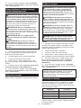
Automatic speed change function
► Fig.8: 1. Mode indicator
Mode indicator status Operation mode
High speed mode
High torque mode

16 ENGLISH
This tool has "high speed mode" and "high torque
mode". It automatically changes operation mode
depending on the work load. When mode indicator
lights up during operation, the tool is in high torque
mode.
Stopper pin
CAUTION: Always hold the handle when
releasing the stopper pin. Otherwise the handle
springs up and it may result in personal injury.
To release the stopper pin, keep applying a slight
downward pressure on the handle and then pulling the
stopper pin.
► Fig.9: 1. Stopper pin
Blade guard
WARNING: Never defeat or remove the blade
guard or the spring which attaches to the guard.
An exposed blade as a result of defeated guarding
may result in serious personal injury during operation.
WARNING: Never use the tool if the blade
guard or spring are damaged, faulty or removed.
Operation of the tool with a damaged, faulty or
removed guard may result in serious personal injury.
CAUTION: Always maintain the blade guard in
good condition for safe operation. Stop the operation
immediately if there are any irregularity of the blade
guard. Check to assure spring loaded return action
of guard.
For tools with blade guard release lever
► Fig.10: 1. Blade guard A 2. Blade guard B
When lowering the handle, the blade guard A rises
automatically. The blade guard B rises as it contacts a
workpiece. The guards are spring loaded so it returns to
its original position when the cut is completed and the
handle is raised.
For tools without blade guard release lever
► Fig.11: 1. Blade guard
When lowering the handle, the blade guard raises
automatically. The guard is spring loaded so it returns to
its original position when the cut is completed and the
handle is raised.
Cleaning
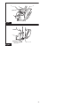
► Fig.12: 1. Blade guard
If the transparent blade guard becomes dirty, or saw-
dust adheres to it in such a way that the blade and/or
workpiece is no longer easily visible, remove the battery
cartridge and clean the guard carefully with a damp
cloth. Do not use solvents or any petroleum-based
cleaners on the plastic guard because this may cause
damage to the guard.
For cleaning, raise the blade guard by referring to
"Installing or removing saw blade".
After cleaning, make sure to return the blade and center
cover and tighten the hex socket bolt.
1. Make sure that the tool is switched off and the
battery cartridges are removed.
2. Turn the hex socket bolt counterclockwise using
the supplied hex wrench with holding the center cover.
3. Raise the blade guard and center cover.
4. When cleaning is complete, return the center
cover and tighten the hex socket bolt by performing the
steps above in reverse.
WARNING: Do not remove spring holding
blade guard. If guard becomes damaged in course
of time or UV light exposure, contact a Makita ser-
vice center for replacement. DO NOT DEFEAT OR
REMOVE GUARD.
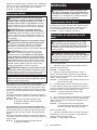
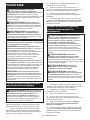
Positioning kerf board
This tool is provided with the kerf boards in the turn
base to minimize tearing on the exit side of a cut. The
kerf boards are factory adjusted so that the saw blade
does not contact the kerf boards. Before use, adjust the
kerf boards as follows:
1. Make sure to remove the battery cartridge. Then,
loosen all the screws (2 each on left and right) securing
the kerf boards.
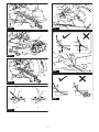
► Fig.13: 1. Kerf board 2. Screw
2. Re-tighten them only to the extent that the kerf
boards can still be easily moved by hand.
3. Lower the handle fully and push in the stopper pin
to lock the handle in the lowered position.
4. Loosen two clamp screws which secure the slide
poles.
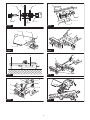
► Fig.14: 1. Thumb screw
5. Pull the carriage toward you fully.
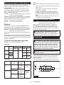
6. Adjust the kerf boards so that the kerf boards just
contact the sides of the blade teeth.
► Fig.15
► Fig.16: 1. Saw blade 2. Blade teeth 3. Kerf board
4. Left bevel cut 5. Straight cut
7. Tighten the front screws (do not tighten rmly).
8. Push the carriage toward the guide fence fully and
adjust the kerf boards so that the kerf boards just con-
tact the sides of blade teeth.
9. Tighten the rear screws (do not tighten rmly).
10.
After adjusting the kerf boards, release the stopper pin
and raise the handle. Then tighten all the screws securely.
NOTICE: After setting the bevel angle ensure
that the kerf boards are adjusted properly. Correct
adjustment of the kerf boards helps to provide proper
support of the workpiece and minimizing workpiece
tear out.
Maintaining maximum cutting
capacity
This tool is factory adjusted to provide the maximum
cutting capacity for a 190 mm saw blade.
When installing a new blade, always check the lower limit
position of the blade, and if necessary, adjust it as follows:
1. Remove the battery cartridge. Then, push the car-
riage toward the guide fence fully and lower the handle
completely.

17 ENGLISH
► Fig.17: 1. Adjusting bolt 2. Guide fence
2. Use the hex wrench to turn the adjusting bolt until
the saw blade comes slightly below the cross section of
the guide fence and the top surface of the turn base.
► Fig.18
3. Rotate the blade by hand while holding the handle
all the way down to be sure that the blade does not
contact any part of the lower base. Re-adjust slightly, if
necessary.
WARNING: After installing a new blade and
with the battery cartridge removed, always be
sure that the blade does not contact any part of
the lower base when the handle is lowered com-
pletely. If a blade makes contact with the base it may
cause kickback and result in serious personal injury.
► Fig.19
Stopper arm
The lower limit position of the blade can be easily
adjusted with the stopper arm. To adjust it, move the
stopper arm in the direction of the arrow as shown in
the gure. Turn the adjusting screw and press down the
handle fully to check the result.
► Fig.20: 1. Adjusting screw 2. Stopper arm
Sub-fence
Country specic
CAUTION: When performing left bevel cuts,
ip the sub-fence outward. Otherwise, it may con-
tact the blade or a part of the tool, and may result in
serious injury to the operator.
► Fig.21: 1. Sub-fence
This tool is equipped with the sub-fence. Usually posi-
tion the sub-fence inside. However, when performing
left bevel cuts, ip it outward.
Adjusting the miter angle
► Fig.22: 1. Turn base 2. Pointer 3. Miter scale
4. Lock lever 5. Grip
1. Loosen the grip counterclockwise.
2. Press down and hold the lock lever, and adjust the
angle of the turn base. Use the pointer and the miter
scale as a guide.
3. Tighten the grip clockwise rmly.
CAUTION: After changing the miter angle,
always secure the turn base by tightening the grip
rmly.
NOTICE: When turning the turn base, be sure to
raise the handle fully.
Adjusting the bevel angle
To adjust the bevel angle, loosen the lever at the rear of
the tool counterclockwise.
► Fig.23: 1. Lever 2. Release button
To tilt the blade to the left, hold the handle and tilt the
carriage. Use the bevel scale and the pointer as a
guide. Then tighten the lever clockwise rmly to secure
the arm.
► Fig.24: 1. Pointer 2. Bevel scale 3. Arm
To tilt the blade to the right, hold the handle and tilt the
carriage to the left slightly, and push the release button.
With the release button pressed, tilt the saw blade to
the right. Then tighten the lever.
CAUTION: After changing the bevel angle,
always secure the arm by tightening the lever
clockwise.
NOTICE: When tilting the saw blade be sure the
handle is fully raised.
NOTICE: When changing bevel angles, be
sure to position the kerf boards appropriately
as explained in the "Positioning kerf boards"
section.
Adjusting the lever position
If the lever does not provide full tightening in course of
time, change the position of the lever. The lever can be
repositioned at every 30° angle.
Loosen and remove the screw that secures the lever.
Remove the lever and install it again so that it points
slightly above the horizontal. Then, tighten the lever
with the screw rmly.
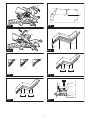
► Fig.25: 1. Lever 2. Screw
Switch action
WARNING: Before installing the battery car-
tridge on the tool, always check to see that the
switch trigger actuates properly and returns to
the "OFF" position when released. Operating a tool
with a switch that does not actuate properly can lead
to loss of control and serious personal injury.
WARNING: Do not use a lock with a shank or
cable any smaller than 6.35 mm (1/4") in diameter.
A smaller shank or cable may not properly lock the
tool in the off position and unintentional operation
may occur resulting in serious personal injury.
WARNING: NEVER use tool without a fully
operative switch trigger. Any tool with an inoper-
ative switch is HIGHLY DANGEROUS and must be
repaired before further usage or serious personal
injury may occur.
WARNING: For your safety, this tool is equipped
with a lock-off button which prevents the tool from
unintended starting. NEVER use the tool if it runs
when you simply pull the switch trigger without
pressing the lock-off button. A switch in need of
repair may result in unintentional operation and seri-
ous personal injury. Return tool to a Makita service
center for proper repairs BEFORE further usage.
WARNING: NEVER defeat the lock-off button
by taping down or some other means. A switch with
a negated lock-off button may result in unintentional
operation and serious personal injury.

18 ENGLISH
NOTICE: Do not pull the switch trigger hard
without pressing in the lock-off button. This can
cause switch breakage.
For tools with blade guard release lever
To prevent the switch trigger from being accidentally
pulled, a lock-off button is provided. To start the tool,
push the blade guard release lever up, press in the
lock-off button and then pull the switch trigger. Release
the switch trigger to stop.
The lock-off button can be pressed from either right or
left.
A hole is provided in the switch trigger for insertion of a
padlock to lock the tool off.
► Fig.26: 1. Blade guard release lever 2. Switch trig-
ger 3. Lock-off button 4. Hole for padlock
For tools without blade guard release lever
To prevent the switch trigger from being accidentally
pulled, a lock-off button is provided. To start the tool,
press in the lock-off button and pull the switch trigger.
Release the switch trigger to stop.
The lock-off button can be pressed from either right or
left.
A hole is provided in the switch trigger for insertion of a
padlock to lock the tool off.
► Fig.27: 1. Lock-off button 2. Switch trigger 3. Hole
for padlock
ASSEMBLY
WARNING: Always be sure that the tool is
switched off and the battery cartridge is removed
before working on the tool. Failure to switch off and
remove the battery cartridge may result in serious
personal injury.
Hex wrench storage
The hex wrench is stored as shown in the gure. When
the hex wrench is needed it can be pulled out of the
wrench holder.
After using the hex wrench it can be stored by returning
it to the wrench holder.
► Fig.28: 1. Wrench holder 2. Hex wrench
Installing or removing saw blade
WARNING: Always be sure that the tool is
switched off and the battery cartridge is removed
before installing or removing the blade. Accidental
start up of the tool may result in serious personal
injury.
CAUTION: Use only the Makita hex wrench
provided to install or remove the blade. Failure
to do so may result in overtightening or insufcient
tightening of the hex socket bolt. This could cause
an injury.
To remove the blade, perform the following steps:
1. Lock the handle in the raised position by pushing
in the stopper pin.
► Fig.29: 1. Stopper pin
2. Use the hex wrench to loosen the hex socket bolt
holding the center cover by turning it counterclockwise.
Then, raise the blade guard and center cover.
► Fig.30: 1. Center cover 2. Hex socket bolt 3. Hex
wrench 4. Blade guard
3. Press the shaft lock to lock the spindle and use
the hex wrench to loosen the hex socket bolt clockwise.
Then remove the hex socket bolt of the spindle, outer
ange and blade.
► Fig.31: 1. Shaft lock 2. Hex socket bolt 3. Outer
ange
4. If the inner ange is removed, install it on the spin-
dle with its blade mounting part facing the blade. If the
ange is installed incorrectly the ange will rub against
the machine.
► Fig.32: 1. Outer ange 2. Saw blade 3. Inner ange
4. Hex socket bolt (left-handed) 5. Spindle
6. Blade mounting part
To install the blade, perform the following steps:
1. Mount the blade carefully onto the inner ange.
Make sure that the direction of the arrow on the blade
matches the direction of the arrow on the blade case.
► Fig.33: 1. Saw blade 2. Arrow
2. Install the outer ange and hex socket bolt, and
then use the hex wrench to tighten the hex socket bolt
(left-handed) of the spindle securely counterclockwise
while pressing the shaft lock.
3. Return the blade guard and center cover to its
original position. Then tighten the hex socket bolt of the
center cover clockwise to secure the center cover.
4. Release the handle from the raised position by
pulling the stopper pin. Lower the handle to make sure
that the blade guard moves properly.
5. Make sure the shaft lock has released spindle
before making cut.
For tool with the inner ange for
15.88 mm hole-diameter saw blade
Country specic
Mount the inner ange with its recessed side facing
outward onto the mounting shaft and then place saw
blade (with the ring attached if needed), outer ange
and hex bolt.
For tool without the ring
► Fig.34: 1. Outer ange 2. Saw blade 3. Inner ange
4. Hex socket bolt (left-handed) 5. Spindle
For tool with the ring
► Fig.35: 1. Outer ange 2. Saw blade 3. Inner ange
4. Hex socket bolt (left-handed) 5. Ring
6. Spindle

19 ENGLISH
WARNING: If the ring is needed to mount the
blade onto the spindle, always be sure that the
correct ring for the blade's arbor hole you intend
to use is installed between the inner and the outer
anges. Use of the incorrect arbor hole ring may
result in the improper mounting of the blade causing
blade movement and severe vibration resulting in
possible loss of control during operation and in seri-
ous personal injury.
For tool with the inner ange for
other than 20 mm or 15.88 mm hole-
diameter saw blade
Country specic
The inner ange has a certain diameter of a blade
mounting part on one side of it and a different diameter
of blade mounting part on the other side. Choose a
correct side on which blade mounting part ts into the
saw blade hole perfectly.
► Fig.36: 1. Outer ange 2. Saw blade 3. Inner ange
4. Hex socket bolt (left-handed) 5. Spindle
6. Blade mounting part
CAUTION: Make sure that the blade mounting
part "a" on the inner ange that is positioned
outside ts into the saw blade hole "a" perfectly.
Mounting the blade on the wrong side can result in
the dangerous vibration.
Dust bag
Optional accessory
The use of the dust bag makes cutting operations
cleaner and dust collection easier.
To attach the dust bag, t it onto the dust nozzle.
To attach the fastener, align the top end of the fastener
with the triangular mark on the dust bag.
When the dust bag is about half full, remove the dust
bag from the tool and pull the fastener out. Empty
the dust bag of its contents, tapping it lightly so as to
remove particles adhering to the insides which might
hamper further collection.
► Fig.37: 1. Dust bag 2. Dust nozzle 3. Fastener
NOTE: If you connect a vacuum cleaner to your saw,
cleaner operations can be performed.
Securing workpiece
WARNING: It is extremely important to always
secure the workpiece correctly with the proper
type of vise. Failure to do so may result in serious
personal injury and cause damage to the tool and/or
the workpiece.
WARNING: When cutting a workpiece that
is longer than the support base of the saw, sup-
port the entire length of the material beyond the
support base and at the same height to keep the
material level. Proper workpiece support helps to
avoid blade pinch and possible kickback which may
result in serious personal injury. Do not rely solely on
the vertical vise and/or horizontal vise to secure the
workpiece. Thin material tends to sag. Support work-
piece over its entire length to avoid blade pinch and
possible KICKBACK.
► Fig.38: 1. Support 2. Turn base
Vertical vise
WARNING: Secure the workpiece rmly
against the turn base and guide fence with the
vise during all operations. Otherwise the material
may move during the cutting operation, cause dam-
age to the blade, and be thrown which may result in
loss of control and serious personal injury.
Install the vertical vise on either the left or right side of
the guide fence or the holder assembly (optional acces-
sory). Insert the vise rod into the hole in the guide fence
or the holder assembly and tighten the lower screw to
secure the vise rod.
► Fig.39: 1. Vise arm 2. Vise rod 3. Guide fence
4. Holder 5. Holder assembly 6. Vise knob
7. Lower screw 8. Upper screw
Position the vise arm according to the thickness and
shape of the workpiece and secure the vise arm by
tightening the upper screw. If the upper screw contacts
the guide fence, install the upper screw on the opposite
side of vise arm. Make sure that no part of the tool
contacts the vise when lowering the handle fully and
pulling or pushing the carriage all the way. If some part
contacts the vise, re-position the vise.
Press the workpiece at against the guide fence and the
turn base. Position the workpiece at the desired cutting
position and secure it rmly by tightening the vise knob.
Horizontal vise
Optional accessory
WARNING: Grip the workpiece only when the
indicator is at the topmost position. Failure to do
so may result in insufcient securing of the workpiece.
This may cause the workpiece to be thrown, cause
damage to the blade or cause the loss of control,
which may result in personal injury.
► Fig.40: 1. Vise knob 2. Indicator 3. Vise shaft
4. Base
The horizontal vise can be installed on the left side of
the base.

20 ENGLISH
By turning the vise knob counterclockwise, the screw
is released and the vise shaft can be moved rapidly in
and out. By turning the vise knob clockwise, the screw
remains secured.
To grip the workpiece, turn the vise knob gently clock-
wise until the indicator reaches its topmost position,
then fasten securely. If the vise knob is forced in or
pulled out while being turned clockwise, the indicator
may stop at an angle. In this case, turn the vise knob
back counterclockwise until the screw is released, and
then turn it again gently clockwise.
The maximum capacity of the horizontal vise is 120 mm
width.
Holders and holder assembly
Optional accessory
WARNING: Always support a long workpiece
so it is level with the top surface of the turn base
for an accurate cut and to prevent dangerous loss
of tool control. Proper workpiece support helps to
avoid blade pinch and possible kickback which may
result in serious personal injury.
The holders and the holder assembly (optional acces-
sory) can be installed on either side as a convenient
means of supporting workpieces horizontally.
Install them on the side of the tool, then tighten the
screws rmly to secure them.
► Fig.41: 1. Holder 2. Holder assembly
When cutting long workpieces, use the holder-rod
assembly (optional accessory). It consists of two holder
assemblies and two rods 12.
► Fig.42: 1. Holder assembly 2. Rod 12
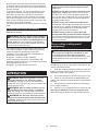
OPERATION
WARNING: Make sure the blade is not con-
tacting the workpiece, etc. before the switch
is turned on. Turning the tool on with the blade in
contact with the workpiece may result in kickback and
serious personal injury.
WARNING: After a cutting operation, do not
raise the blade until it has come to a complete
stop. The raising of a coasting blade may result in
serious personal injury and damage to the workpiece.
WARNING: Do not touch the clamp screws
which secure the slide poles while the saw blade
is rotating. Otherwise the tool may lose control and
result in personal injury.
NOTICE: Before use, be sure to release the
handle from the lowered position by pulling the
stopper pin.
NOTICE: Do not apply excessive pressure on the
handle when cutting. Too much force may result in
overload of the motor and/or decreased cutting ef-
ciency. Press down handle with only as much force as
necessary for smooth cutting and without signicant
decrease in blade speed.
NOTICE: Gently press down the handle to per-
form the cut. If the handle is pressed down with force
or if lateral force is applied, the blade may vibrate and
leave a mark (saw mark) in the workpiece and the
precision of the cut may be impaired.
NOTICE: During a slide cut, gently push the
carriage toward the guide fence without stopping.
If the carriage movement stops during the cut, a mark
may be left in the workpiece and the precision of the
cut may be impaired.
Press cutting (cutting small
workpieces)
WARNING: Firmly tighten two clamp screws
which secure the slide poles clockwise so that
the carriage will not move during operation.
Insufcient tightening of the locking screw may cause
possible kickback which may result in serious per-
sonal injury.
► Fig.43
Workpieces up to 52 mm high and 97 mm wide can be
cut in the following manner.
1. Push the carriage toward the guide fence fully and
tighten two clamp screws which secure the slide poles
clockwise to secure the carriage.
2. Secure the workpiece with the proper type of vise.
3. Switch on the tool without the blade making any
contact and wait until the blade attains full speed before
lowering.
4. Gently lower the handle to the fully lowered posi-
tion to cut the workpiece.
5. When the cut is completed, switch off the tool and
wait until the blade has come to a complete stop
before returning the blade to its fully elevated position.
Pagina se încarcă...
Pagina se încarcă...
Pagina se încarcă...
Pagina se încarcă...
Pagina se încarcă...
Pagina se încarcă...
Pagina se încarcă...
Pagina se încarcă...
Pagina se încarcă...
Pagina se încarcă...
Pagina se încarcă...
Pagina se încarcă...
Pagina se încarcă...
Pagina se încarcă...
Pagina se încarcă...
Pagina se încarcă...
Pagina se încarcă...
Pagina se încarcă...
Pagina se încarcă...
Pagina se încarcă...
Pagina se încarcă...
Pagina se încarcă...
Pagina se încarcă...
Pagina se încarcă...
Pagina se încarcă...
Pagina se încarcă...
Pagina se încarcă...
Pagina se încarcă...
Pagina se încarcă...
Pagina se încarcă...
Pagina se încarcă...
Pagina se încarcă...
Pagina se încarcă...
Pagina se încarcă...
Pagina se încarcă...
Pagina se încarcă...
Pagina se încarcă...
Pagina se încarcă...
Pagina se încarcă...
Pagina se încarcă...
Pagina se încarcă...
Pagina se încarcă...
Pagina se încarcă...
Pagina se încarcă...
Pagina se încarcă...
Pagina se încarcă...
Pagina se încarcă...
Pagina se încarcă...
Pagina se încarcă...
Pagina se încarcă...
Pagina se încarcă...
Pagina se încarcă...
Pagina se încarcă...
Pagina se încarcă...
Pagina se încarcă...
Pagina se încarcă...
Pagina se încarcă...
Pagina se încarcă...
Pagina se încarcă...
Pagina se încarcă...
Pagina se încarcă...
Pagina se încarcă...
Pagina se încarcă...
Pagina se încarcă...
Pagina se încarcă...
Pagina se încarcă...
Pagina se încarcă...
Pagina se încarcă...
Pagina se încarcă...
Pagina se încarcă...
Pagina se încarcă...
Pagina se încarcă...
Pagina se încarcă...
Pagina se încarcă...
Pagina se încarcă...
Pagina se încarcă...
Pagina se încarcă...
Pagina se încarcă...
Pagina se încarcă...
Pagina se încarcă...
Pagina se încarcă...
Pagina se încarcă...
Pagina se încarcă...
Pagina se încarcă...
Pagina se încarcă...
Pagina se încarcă...
Pagina se încarcă...
Pagina se încarcă...
Pagina se încarcă...
Pagina se încarcă...
Pagina se încarcă...
Pagina se încarcă...
Pagina se încarcă...
Pagina se încarcă...
Pagina se încarcă...
Pagina se încarcă...
Pagina se încarcă...
Pagina se încarcă...
Pagina se încarcă...
Pagina se încarcă...
Pagina se încarcă...
Pagina se încarcă...
Pagina se încarcă...
Pagina se încarcă...
Pagina se încarcă...
Pagina se încarcă...
Pagina se încarcă...
Pagina se încarcă...
Pagina se încarcă...
Pagina se încarcă...
Pagina se încarcă...
Pagina se încarcă...
Pagina se încarcă...
Pagina se încarcă...
Pagina se încarcă...
Pagina se încarcă...
Pagina se încarcă...
Pagina se încarcă...
Pagina se încarcă...
Pagina se încarcă...
Pagina se încarcă...
Pagina se încarcă...
Pagina se încarcă...
Pagina se încarcă...
Pagina se încarcă...
Pagina se încarcă...
Pagina se încarcă...
Pagina se încarcă...
Pagina se încarcă...
Pagina se încarcă...
Pagina se încarcă...
Pagina se încarcă...
Pagina se încarcă...
Pagina se încarcă...
Pagina se încarcă...
Pagina se încarcă...
Pagina se încarcă...
Pagina se încarcă...
Pagina se încarcă...
Pagina se încarcă...
Pagina se încarcă...
Pagina se încarcă...
Pagina se încarcă...
Pagina se încarcă...
-
 1
1
-
 2
2
-
 3
3
-
 4
4
-
 5
5
-
 6
6
-
 7
7
-
 8
8
-
 9
9
-
 10
10
-
 11
11
-
 12
12
-
 13
13
-
 14
14
-
 15
15
-
 16
16
-
 17
17
-
 18
18
-
 19
19
-
 20
20
-
 21
21
-
 22
22
-
 23
23
-
 24
24
-
 25
25
-
 26
26
-
 27
27
-
 28
28
-
 29
29
-
 30
30
-
 31
31
-
 32
32
-
 33
33
-
 34
34
-
 35
35
-
 36
36
-
 37
37
-
 38
38
-
 39
39
-
 40
40
-
 41
41
-
 42
42
-
 43
43
-
 44
44
-
 45
45
-
 46
46
-
 47
47
-
 48
48
-
 49
49
-
 50
50
-
 51
51
-
 52
52
-
 53
53
-
 54
54
-
 55
55
-
 56
56
-
 57
57
-
 58
58
-
 59
59
-
 60
60
-
 61
61
-
 62
62
-
 63
63
-
 64
64
-
 65
65
-
 66
66
-
 67
67
-
 68
68
-
 69
69
-
 70
70
-
 71
71
-
 72
72
-
 73
73
-
 74
74
-
 75
75
-
 76
76
-
 77
77
-
 78
78
-
 79
79
-
 80
80
-
 81
81
-
 82
82
-
 83
83
-
 84
84
-
 85
85
-
 86
86
-
 87
87
-
 88
88
-
 89
89
-
 90
90
-
 91
91
-
 92
92
-
 93
93
-
 94
94
-
 95
95
-
 96
96
-
 97
97
-
 98
98
-
 99
99
-
 100
100
-
 101
101
-
 102
102
-
 103
103
-
 104
104
-
 105
105
-
 106
106
-
 107
107
-
 108
108
-
 109
109
-
 110
110
-
 111
111
-
 112
112
-
 113
113
-
 114
114
-
 115
115
-
 116
116
-
 117
117
-
 118
118
-
 119
119
-
 120
120
-
 121
121
-
 122
122
-
 123
123
-
 124
124
-
 125
125
-
 126
126
-
 127
127
-
 128
128
-
 129
129
-
 130
130
-
 131
131
-
 132
132
-
 133
133
-
 134
134
-
 135
135
-
 136
136
-
 137
137
-
 138
138
-
 139
139
-
 140
140
-
 141
141
-
 142
142
-
 143
143
-
 144
144
-
 145
145
-
 146
146
-
 147
147
-
 148
148
-
 149
149
-
 150
150
-
 151
151
-
 152
152
-
 153
153
-
 154
154
-
 155
155
-
 156
156
-
 157
157
-
 158
158
-
 159
159
-
 160
160
-
 161
161
-
 162
162
-
 163
163
-
 164
164


Makita DLS714 Manual de utilizare
- Categorie
- Ferăstraie mitre
- Tip
- Manual de utilizare
Lucrări înrudite
-
Makita LS1040S Manual de utilizare
-
Makita DLS714 Manual de utilizare
-
Makita LS0714 Manual de utilizare
-
Makita LS1018 Manual de utilizare
-
Makita HS012G Cordless Circular Saw Manual de utilizare
-
Makita LS1440 Manual de utilizare
-
-
Makita HS003G Manual de utilizare
-
-
Makita DHS680 Manual de utilizare
Alte documente
-
Skil 1131 AA Manual de utilizare
-
Hikoki C3612DRA Manual de utilizare
-
Maktec MT431 Manual de utilizare
-
Worx WU433 Fișa cu date
-
Maktec MT402 Manual de utilizare
-
RAIDER Pro RDP-CS26X Manual de utilizare
-
-
 Raider Power Tools RD-CSL01 Manual de utilizare
-
 Raider Power Tools RD-MS10 Manual de utilizare
-
Dolmar LG-184 X2 Manualul proprietarului

