Makita GA048G Manual de utilizare
- Categorie
- Unelte electrice
- Tip
- Manual de utilizare

GA048G
GA049G
GA050G
GA051G
EN Cordless Angle Grinder INSTRUCTION MANUAL 8
PL Akumulatorowa szlierka
kątowa INSTRUKCJA OBSŁUGI 22
HU Akkumulátoros sarokcsiszoló HASZNÁLATI KÉZIKÖNYV 37
SK Ručná uhlová brúska NÁVOD NA OBSLUHU 52
CS Akumulátorová úhlová
bruska NÁVOD K OBSLUZE 66
UK Бездротова кутова
шліфувальна машина ІНСТРУКЦІЯ З
ЕКСПЛУАТАЦІЇ 80
RO Polizor unghiular cu
acumulator MANUAL DE INSTRUCŢIUNI 96
DE Akku-Winkelschleifer BETRIEBSANLEITUNG 111

2
3
11
1
2
Fig.1
1
2
Fig.2
1
Fig.3
1
2
Fig.4
Fig.5
1
2
3
Fig.6

3
2
B
1
A
B
Fig.7
2
1
A
C
C
Fig.8
Fig.9
2
3
4
1
Fig.10
1
2
Fig.11
1
2
3
4
Fig.12

4
1
2
3
4
Fig.13
1
2
3
Fig.14
1
2
4
3
Fig.15
1
Fig.16
12
Fig.17
Fig.18
1
3
2
4
Fig.19
16 mm (5/8″) 16 mm (5/8″)
11
44
23
Fig.20

5
11
44
23
Fig.21
11
44
23
Fig.22
11
44
23
Fig.23
1
Fig.24
1
Fig.25
1
Fig.26
1
2
4
5
6
3
Fig.27
Fig.28

6
Fig.29
Fig.30
Fig.31
Fig.32
Fig.33
Fig.34
Fig.35
1
2
Fig.36

7
1
Fig.37

8ENGLISH
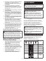
ENGLISH (Original instructions)
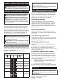
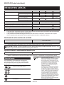
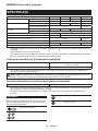
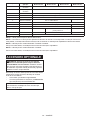
SPECIFICATIONS
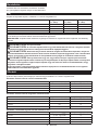
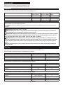
Model: GA048G GA049G GA050G GA051G
Applicable grinding wheel Max. wheel diameter 100 mm 115 mm 125 mm 150 mm
Max. wheel thickness 6.4 mm 7.2 mm 6.4 mm
Applicable cut-o wheel Max. wheel diameter 105 mm 115 mm 125 mm 150 mm
Max. wheel thickness 3.2 mm 3.0 mm
Applicable wire wheel brush Max. wheel diameter 100 mm 115 mm 125 mm
Max. wheel thickness 20 mm
Spindle thread M10 M14 or 5/8″ (country specic)
Max. spindle length 18 mm 23 mm
No load speed (n0) / Rated speed (n) 11,000 min-1 9,000 min-1
Overall length (with BL4040) 410 mm
Net weight 2.8 - 5.2 kg 3.0 - 5.4 kg 3.1 - 4.7 kg
Rated voltage D.C. 36 V - 40 V max
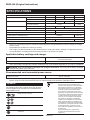
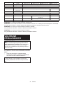
• Due to our continuing program of research and development, the specications herein are subject to change
without notice.
• Specications may dier from country to country.
• The weight may dier depending on the attachment(s), including the battery cartridge. The lightest and heavi-
est combinations, according to EPTA-Procedure 01/2014, are shown in the table.
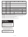
Applicable battery cartridge and charger
Battery cartridge BL4020 / BL4025* / BL4040* / BL4050F* / BL4080F
* : Recommended battery
Charger DC40RA / DC40RB / DC40RC
•
Some of the battery cartridges and chargers listed above may not be available depending on your region of residence.
WARNING: Only use the battery cartridges and chargers listed above. Use of any other battery cartridges
and chargers may cause injury and/or re.
Recommended cord connected power source
Portable power pack PDC01 / PDC1200
• The cord connected power source(s) listed above may not be available depending on your region of residence.
• Before using the cord connected power source, read instruction and cautionary markings on them.
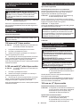
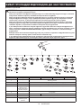
Symbols
The followings show the symbols which may be used
for the equipment. Be sure that you understand their
meaning before use.
Read instruction manual.
Wear safety glasses.
Always operate with two hands.
Do not use the wheel guard for cut-o
operations.
Ni-MH
Li-ion
Only for EU countries
Due to the presence of hazardous com-
ponents in the equipment, waste electrical
and electronic equipment, accumulators
and batteries may have a negative impact
on the environment and human health.
Do not dispose of electrical and electronic
appliances or batteries with household waste!
In accordance with the European Directive
on waste electrical and electronic equip-
ment and on accumulators and batteries
and waste accumulators and batteries,
as well as their adaptation to national law,
waste electrical equipment, batteries and
accumulators should be stored separately
and delivered to a separate collection point
for municipal waste, operating in accor-
dance with the regulations on environmen-
tal protection.
This is indicated by the symbol of the
crossed-out wheeled bin placed on the
equipment.

9ENGLISH
Intended use
The tool is intended for grinding, sanding, wire brush-
ing, hole cutting and cutting of metal and stone materi-
als without the use of water.
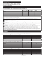
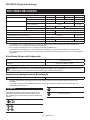
Noise
The typical A-weighted noise level determined according to EN62841-2-3:
Model Sound pressure
level (LpA) : (dB(A)) Sound power level
(LWA) : (dB(A)) Uncertainty (K) :
(dB(A))
GA048G 84 92 3
GA049G 85 93 3
GA050G 85 93 3
GA051G 85 93 3
NOTE: The declared noise emission value(s) has been measured in accordance with a standard test method and
may be used for comparing one tool with another.
NOTE: The declared noise emission value(s) may also be used in a preliminary assessment of exposure.
WARNING: Wear ear protection.
WARNING: The noise emission during actual use of the power tool can dier from the declared val-
ue(s) depending on the ways in which the tool is used especially what kind of workpiece is processed.
WARNING: Be sure to identify safety measures to protect the operator that are based on an estimation
of exposure in the actual conditions of use (taking account of all parts of the operating cycle such as the
times when the tool is switched o and when it is running idle in addition to the trigger time).
WARNING: Grinding thin sheets of metal or other easily vibrating structures with a large surface can
result in a total noise emission much higher (up to 15 dB) than the declared noise emission values.
Set heavy exible damping mats or such to those workpieces to prevent them from emitting sound.
Take the increased noise emission into consideration for both the risk assessment of noise exposure and
selecting adequate hearing protection.
Vibration
The vibration total value (tri-axial vector sum) determined according to EN62841-2-3:
Work mode: surface grinding with normal side grip
Model
Vibration emission (ah, AG) : (m/s2)
Uncertainty (K) : (m/s2)
GA048G 8.2 1.5
GA049G 8.5 1.5
GA050G 8.9 2.2
GA051G 12.1 1.5
Work mode: surface grinding with anti vibration side grip
Model
Vibration emission (ah, AG) : (m/s2)
Uncertainty (K) : (m/s2)
GA048G 7.1 1.5
GA049G 7.7 1.5
GA050G 8.8 1.5
GA051G 12.7 1.6
Work mode: disc sanding with normal side grip
Model
Vibration emission (ah, DS) : (m/s2)
Uncertainty (K) : (m/s2)
GA048G 2.5 m/s2 or less 1.5
GA049G 2.8 1.5
GA050G 2.6 1.5
GA051G 3.1 1.5

10 ENGLISH
Work mode: disc sanding with anti vibration side grip
Model
Vibration emission (ah, DS) : (m/s2)
Uncertainty (K) : (m/s2)
GA048G 2.5 m/s2 or less 1.5
GA049G 2.8 1.5
GA050G 2.5 1.5
GA051G 3.5 1.5
NOTE: The declared vibration total value(s) has been measured in accordance with a standard test method and
may be used for comparing one tool with another.
NOTE: The declared vibration total value(s) may also be used in a preliminary assessment of exposure.
WARNING: The vibration emission during actual use of the power tool can dier from the declared
value(s) depending on the ways in which the tool is used especially what kind of workpiece is processed.
WARNING: Be sure to identify safety measures to protect the operator that are based on an estimation
of exposure in the actual conditions of use (taking account of all parts of the operating cycle such as the
times when the tool is switched o and when it is running idle in addition to the trigger time).
WARNING: The declared vibration emission value is used for main applications of the power tool. However if
the power tool is used for other applications, the vibration emission value may be dierent.
Declarations of Conformity
For European countries only
The Declarations of conformity are included in Annex A
to this instruction manual.
SAFETY WARNINGS
General power tool safety warnings
WARNING Read all safety warnings, instructions,
illustrations and specications provided with this
power tool. Failure to follow all instructions listed below
may result in electric shock, re and/or serious injury.
Save all warnings and instruc-
tions for future reference.
The term "power tool" in the warnings refers to your
mains-operated (corded) power tool or battery-operated
(cordless) power tool.
Cordless grinder safety warnings
Safety warnings common for grinding, sanding,
wire brushing, or cutting-o operations:
1.
This power tool is intended to function as a grinder,
sander, wire brush, hole cutter or cut-o tool. Read
all safety warnings, instructions, illustrations and
specications provided with this power tool. Failure
to follow all instructions listed below may result in
electric shock, re and/or serious injury.
2. Operations such as polishing are not to be
performed with this power tool. Operations for
which the power tool was not designed may create
a hazard and cause personal injury.
3. Do not convert this power tool to operate in
a way which is not specically designed and
specied by the tool manufacturer. Such a con-
version may result in a loss of control and cause
serious personal injury.
4. Do not use accessories which are not spe-
cically designed and specied by the tool
manufacturer. Just because the accessory can
be attached to your power tool, it does not assure
safe operation.
5. The rated speed of the accessory must be at
least equal to the maximum speed marked on
the power tool. Accessories running faster than
their rated speed can break and y apart.
6. The outside diameter and the thickness of your
accessory must be within the capacity rating
of your power tool. Incorrectly sized accessories
cannot be adequately guarded or controlled.
7. The dimensions of the accessory mounting
must t the dimensions of the mounting hard-
ware of the power tool. Accessories that do not
match the mounting hardware of the power tool
will run out of balance, vibrate excessively and
may cause loss of control.
8. Do not use a damaged accessory. Before each
use inspect the accessory such as abrasive
wheels for chips and cracks, backing pad for
cracks, tear or excess wear, wire brush for
loose or cracked wires. If power tool or acces-
sory is dropped, inspect for damage or install
an undamaged accessory. After inspecting and
installing an accessory, position yourself and
bystanders away from the plane of the rotating
accessory and run the power tool at maximum
no-load speed for one minute. Damaged acces-
sories will normally break apart during this test
time.
9. Wear personal protective equipment.
Depending on application, use face shield,
safety goggles or safety glasses. As appro-
priate, wear dust mask, hearing protectors,
gloves and workshop apron capable of stop-
ping small abrasive or workpiece fragments.
The eye protection must be capable of stopping
ying debris generated by various applications.
The dust mask or respirator must be capable
of ltrating particles generated by the particular
application. Prolonged exposure to high intensity
noise may cause hearing loss.

11 ENGLISH
10. Keep bystanders a safe distance away from
work area. Anyone entering the work area
must wear personal protective equipment.
Fragments of workpiece or of a broken accessory
may y away and cause injury beyond immediate
area of operation.
11. Hold the power tool by insulated gripping
surfaces only, when performing an operation
where the cutting tool may contact hidden
wiring. Contact with a "live" wire will also make
exposed metal parts of the power tool "live" and
could give the operator an electric shock.
12. Never lay the power tool down until the acces-
sory has come to a complete stop. The spinning
accessory may grab the surface and pull the
power tool out of your control.
13. Do not run the power tool while carrying it at
your side. Accidental contact with the spinning
accessory could snag your clothing, pulling the
accessory into your body.
14. Regularly clean the power tool’s air vents. The
motor’s fan will draw the dust inside the housing
and excessive accumulation of powdered metal
may cause electrical hazards.
15. Do not operate the power tool near ammable
materials. Sparks could ignite these materials.
16. Do not use accessories that require liquid
coolants. Using water or other liquid coolants
may result in electrocution or shock.
Kickback and related warnings:
Kickback is a sudden reaction to a pinched or snagged
rotating wheel, backing pad, brush or any other acces-
sory. Pinching or snagging causes rapid stalling of the
rotating accessory which in turn causes the uncon-
trolled power tool to be forced in the direction opposite
of the accessory’s rotation at the point of the binding.
For example, if an abrasive wheel is snagged or
pinched by the workpiece, the edge of the wheel that is
entering into the pinch point can dig into the surface of
the material causing the wheel to climb out or kick out.
The wheel may either jump toward or away from the
operator, depending on direction of the wheel’s move-
ment at the point of pinching. Abrasive wheels may also
break under these conditions.
Kickback is the result of power tool misuse and/or
incorrect operating procedures or conditions and can be
avoided by taking proper precautions as given below.
1.
Maintain a rm grip with both hands on the
power tool and position your body and arms
to allow you to resist kickback forces. Always
use auxiliary handle, if provided, for maximum
control over kickback or torque reaction during
start-up. The operator can control torque reactions
or kickback forces, if proper precautions are taken.
2. Never place your hand near the rotating acces-
sory. Accessory may kickback over your hand.
3. Do not position your body in the area where
power tool will move if kickback occurs.
Kickback will propel the tool in direction opposite
to the wheel’s movement at the point of snagging.
4. Use special care when working corners, sharp
edges, etc. Avoid bouncing and snagging the
accessory. Corners, sharp edges or bouncing
have a tendency to snag the rotating accessory
and cause loss of control or kickback.
5. Do not attach a saw chain woodcarving blade,
segmented diamond wheel with a peripheral
gap greater than 10 mm or toothed saw blade.
Such blades create frequent kickback and loss of
control.
Safety warnings specic for grinding and cut-
ting-o operations:
1. Use only wheel types that are specied
for your power tool and the specic guard
designed for the selected wheel. Wheels for
which the power tool was not designed cannot be
adequately guarded and are unsafe.
2. The grinding surface of centre depressed
wheels must be mounted below the plane of
the guard lip. An improperly mounted wheel that
projects through the plane of the guard lip cannot
be adequately protected.
3. The guard must be securely attached to the
power tool and positioned for maximum safety,
so the least amount of wheel is exposed
towards the operator. The guard helps to protect
the operator from broken wheel fragments, acci-
dental contact with wheel and sparks that could
ignite clothing.
4.
Wheels must be used only for specied applica-
tions. For example: do not grind with the side of
cut-o wheel. Abrasive cut-o wheels are intended
for peripheral grinding, side forces applied to these
wheels may cause them to shatter.
5. Always use undamaged wheel anges that are
of correct size and shape for your selected
wheel. Proper wheel anges support the wheel
thus reducing the possibility of wheel breakage.
Flanges for cut-o wheels may be dierent from
grinding wheel anges.
6. Do not use worn down wheels from larger
power tools. A wheel intended for larger power
tool is not suitable for the higher speed of a
smaller tool and may burst.
7. When using dual purpose wheels always use
the correct guard for the application being
performed. Failure to use the correct guard may
not provide the desired level of guarding, which
could lead to serious injury.
Additional safety warnings specic for cutting-o
operations:
1. Do not “jam” the cut-o wheel or apply exces-
sive pressure. Do not attempt to make an
excessive depth of cut. Overstressing the wheel
increases the loading and susceptibility to twisting
or binding of the wheel in the cut and the possibil-
ity of kickback or wheel breakage.
2. Do not position your body in line with and
behind the rotating wheel. When the wheel, at
the point of operation, is moving away from your
body, the possible kickback may propel the spin-
ning wheel and the power tool directly at you.
3. When the wheel is binding or when interrupt-
ing a cut for any reason, switch o the power
tool and hold it motionless until the wheel
comes to a complete stop. Never attempt to
remove the cut-o wheel from the cut while
the wheel is in motion otherwise kickback may
occur. Investigate and take corrective action to
eliminate the cause of wheel binding.

12 ENGLISH
4. Do not restart the cutting operation in the
workpiece. Let the wheel reach full speed and
carefully re-enter the cut. The wheel may bind,
walk up or kickback if the power tool is restarted in
the workpiece.
5. Support panels or any oversized workpiece to
minimize the risk of wheel pinching and kick-
back. Large workpieces tend to sag under their
own weight. Supports must be placed under the
workpiece near the line of cut and near the edge
of the workpiece on both sides of the wheel.
6. Use extra caution when making a “pocket cut”
into existing walls or other blind areas. The
protruding wheel may cut gas or water pipes, elec-
trical wiring or objects that can cause kickback.
7. Do not attempt to do curved cutting.
Overstressing the wheel increases the loading and
susceptibility to twisting or binding of the wheel
in the cut and the possibility of kickback or wheel
breakage, which can lead to serious injury.
8. Before using a segmented diamond wheel,
make sure that the diamond wheel has the
peripheral gap between segments of 10 mm or
less, only with a negative rake angle.
Safety warnings specic for sanding operations:
1. Use proper sized sanding disc paper. Follow
manufacturers recommendations, when
selecting sanding paper. Larger sanding paper
extending too far beyond the sanding pad pres-
ents a laceration hazard and may cause snagging,
tearing of the disc or kickback.
Safety warnings specic for wire brushing
operations:
1. Be aware that wire bristles are thrown by the
brush even during ordinary operation. Do not
overstress the wires by applying excessive
load to the brush. The wire bristles can easily
penetrate light clothing and/or skin.
2. If the use of a guard is specied for wire
brushing, do not allow any interference of the
wire wheel or brush with the guard. Wire wheel
or brush may expand in diameter due to work load
and centrifugal forces.
Additional Safety Warnings:
1. When using depressed centre grinding wheels,
be sure to use only berglass-reinforced
wheels.
2. NEVER USE Stone Cup type wheels with this
grinder. This grinder is not designed for these
types of wheels and the use of such a product
may result in serious personal injury.
3. Be careful not to damage the spindle, the
ange (especially the installing surface) or the
lock nut. Damage to these parts could result in
wheel breakage.
4. Make sure the wheel is not contacting the
workpiece before the switch is turned on.
5. Before using the tool on an actual workpiece,
let it run for a while. Watch for vibration or
wobbling that could indicate poor installation
or a poorly balanced wheel.
6. Use the specied surface of the wheel to per-
form the grinding.
7. Do not leave the tool running. Operate the tool
only when hand-held.
8. Do not touch the workpiece immediately after
operation; it may be extremely hot and could
burn your skin.
9. Do not touch accessories immediately after
operation; it may be extremely hot and could
burn your skin.
10. Observe the instructions of the manufacturer
for correct mounting and use of wheels and
accessories. Incorrect mounting and use may
result in personal injury.
11. Handle and store wheels with care.
12. Do not use separate reducing bushings or
adaptors to adapt large hole abrasive wheels.
13. Use only anges specied for this tool.
14. For tools intended to be tted with threaded
hole wheel, ensure that the thread in the wheel
is long enough to accept the spindle length.
15. Check that the workpiece is properly
supported.
16. Pay attention that the wheel continues to
rotate after the tool is switched o.
17. If working place is extremely hot and humid,
or badly polluted by conductive dust, use a
short-circuit breaker (30 mA) to assure opera-
tor safety.
18. Do not use the tool on any materials contain-
ing asbestos.
19. When use cut-o wheel, always work with
the dust collecting wheel guard if required by
domestic regulation.
20. Cutting discs must not be subjected to any
lateral pressure.
21. Do not use cloth work gloves during operation.
Fibers from cloth gloves may enter the tool, which
causes tool breakage.
22. Before operation, make sure that there is no
buried object such as electric pipe, water pipe
or gas pipe in the workpiece. Otherwise, it may
cause an electric shock, electrical leakage or gas
leak.
23. If a blotter is attached to the wheel, do not
remove it. The diameter of the blotter must be
larger than the lock nut, outer ange, and inner
ange.
24. Before installing a grinding wheel, always
check that the blotter part does not have any
abnormalities such as chips or cracks.
25. Tighten the lock nut properly. Overtightening
the wheel can cause breakage and insucient
tightening can cause uttering.
SAVE THESE INSTRUCTIONS.
WARNING: DO NOT let comfort or familiarity
with product (gained from repeated use) replace
strict adherence to safety rules for the subject
product. MISUSE or failure to follow the safety
rules stated in this instruction manual may cause
serious personal injury.

13 ENGLISH
Important safety instructions for
battery cartridge
1. Before using battery cartridge, read all instruc-
tions and cautionary markings on (1) battery
charger, (2) battery, and (3) product using
battery.
2. Do not disassemble or tamper with the battery
cartridge. It may result in a re, excessive heat,
or explosion.
3. If operating time has become excessively
shorter, stop operating immediately. It may
result in a risk of overheating, possible burns
and even an explosion.
4. If electrolyte gets into your eyes, rinse them
out with clear water and seek medical atten-
tion right away. It may result in loss of your
eyesight.
5. Do not short the battery cartridge:
(1) Do not touch the terminals with any con-
ductive material.
(2) Avoid storing battery cartridge in a con-
tainer with other metal objects such as
nails, coins, etc.
(3) Do not expose battery cartridge to water
or rain.
A battery short can cause a large current
ow, overheating, possible burns and even a
breakdown.
6. Do not store and use the tool and battery car-
tridge in locations where the temperature may
reach or exceed 50 °C (122 °F).
7. Do not incinerate the battery cartridge even if
it is severely damaged or is completely worn
out. The battery cartridge can explode in a re.
8. Do not nail, cut, crush, throw, drop the battery
cartridge, or hit against a hard object to the
battery cartridge. Such conduct may result in a
re, excessive heat, or explosion.
9. Do not use a damaged battery.
10. The contained lithium-ion batteries are subject
to the Dangerous Goods Legislation require-
ments.
For commercial transports e.g. by third parties,
forwarding agents, special requirement on pack-
aging and labeling must be observed.
For preparation of the item being shipped, consult-
ing an expert for hazardous material is required.
Please also observe possibly more detailed
national regulations.
Tape or mask o open contacts and pack up the
battery in such a manner that it cannot move
around in the packaging.
11. When disposing the battery cartridge, remove
it from the tool and dispose of it in a safe
place. Follow your local regulations relating to
disposal of battery.
12. Use the batteries only with the products
specied by Makita. Installing the batteries to
non-compliant products may result in a re, exces-
sive heat, explosion, or leak of electrolyte.
13. If the tool is not used for a long period of time,
the battery must be removed from the tool.
14. During and after use, the battery cartridge may
take on heat which can cause burns or low
temperature burns. Pay attention to the han-
dling of hot battery cartridges.
15. Do not touch the terminal of the tool imme-
diately after use as it may get hot enough to
cause burns.
16. Do not allow chips, dust, or soil stuck into the
terminals, holes, and grooves of the battery
cartridge. It may cause heating, catching re,
burst and malfunction of the tool or battery car-
tridge, resulting in burns or personal injury.
17. Unless the tool supports the use near
high-voltage electrical power lines, do not use
the battery cartridge near high-voltage electri-
cal power lines. It may result in a malfunction or
breakdown of the tool or battery cartridge.
18. Keep the battery away from children.
SAVE THESE INSTRUCTIONS.
CAUTION: Only use genuine Makita batteries.
Use of non-genuine Makita batteries, or batteries that
have been altered, may result in the battery bursting
causing res, personal injury and damage. It will
also void the Makita warranty for the Makita tool and
charger.
Tips for maintaining maximum
battery life
1. Charge the battery cartridge before completely
discharged. Always stop tool operation and
charge the battery cartridge when you notice
less tool power.
2. Never recharge a fully charged battery car-
tridge. Overcharging shortens the battery
service life.
3. Charge the battery cartridge with room tem-
perature at 10 °C - 40 °C (50 °F - 104 °F). Let
a hot battery cartridge cool down before
charging it.
4. When not using the battery cartridge, remove
it from the tool or the charger.
5. Charge the battery cartridge if you do not use
it for a long period (more than six months).

14 ENGLISH
FUNCTIONAL DESCRIPTION
WARNING: Always be sure that the tool is
switched o and the battery cartridge is removed
before adjusting or checking function on the tool.
Installing or removing battery cartridge
CAUTION: Always switch o the tool before
installing or removing of the battery cartridge.
CAUTION: Hold the tool and the battery car-
tridge rmly when installing or removing battery
cartridge. Failure to hold the tool and the battery
cartridge rmly may cause them to slip o your hands
and result in damage to the tool and battery cartridge
and a personal injury.
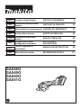
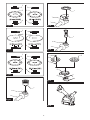
► Fig.1: 1. Red indicator 2. Button 3. Battery cartridge
To remove the battery cartridge, slide it from the tool
while sliding the button on the front of the cartridge.
To install the battery cartridge, align the tongue on the
battery cartridge with the groove in the housing and slip
it into place. Insert it all the way until it locks in place
with a little click. If you can see the red indicator as
shown in the gure, it is not locked completely.
CAUTION: Always install the battery cartridge
fully until the red indicator cannot be seen. If not,
it may accidentally fall out of the tool, causing injury to
you or someone around you.
CAUTION: Do not install the battery cartridge
forcibly. If the cartridge does not slide in easily, it is
not being inserted correctly.
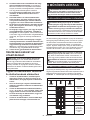
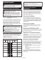
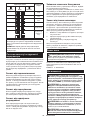
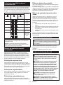
Indicating the remaining battery capacity
Press the check button on the battery cartridge to indi-
cate the remaining battery capacity. The indicator lamps
light up for a few seconds.
► Fig.2: 1. Indicator lamps 2. Check button
Indicator lamps Remaining
capacity
Lighted O Blinking
75% to 100%
50% to 75%
25% to 50%
0% to 25%
Charge the
battery.
The battery
may have
malfunctioned.
NOTE: Depending on the conditions of use and the
ambient temperature, the indication may dier slightly
from the actual capacity.
NOTE: The rst (far left) indicator lamp will blink when
the battery protection system works.
Tool / battery protection system
The tool is equipped with a tool/battery protection sys-
tem. This system automatically cuts o power to the
motor to extend tool and battery life. The tool will auto-
matically stop during operation if the tool or battery is
placed under one of the following conditions:
Overload protection
When the tool/battery is operated in a manner that
causes it to draw an abnormally high current, the tool
automatically stops without any indication. In this sit-
uation, turn the tool o and stop the application that
caused the tool to become overloaded. Then turn the
tool on to restart.
Overheat protection
When the tool/battery is overheated, the tool stops
automatically. Let the tool cool down before turning the
tool on again.
Overdischarge protection
When the battery capacity is not enough, the tool stops
automatically. In this case, remove the battery from the
tool and charge the battery.
Releasing protection lock
When the protection system works repeatedly, the tool
is locked.
In this situation, the tool does not start even if turning
the tool o and on. To release the protection lock,
remove the battery, set it to the battery charger and wait
until the charging nishes.
Protections against other causes
Protection system is also designed for other causes
that could damage the tool and allows the tool to stop
automatically. Take all the following steps to clear the
causes, when the tool has been brought to a temporary
halt or stop in operation.
1.
Turn the tool o, and then turn it on again to restart.
2. Charge the battery(ies) or replace it/them with
recharged battery(ies).
3. Let the tool and battery(ies) cool down.
If no improvement can be found by restoring protection
system, then contact your local Makita Service Center.
Shaft lock
WARNING: Never actuate the shaft lock when
the spindle is moving. It may cause serious injury or
the tool damage.
Press the shaft lock to prevent spindle rotation when
installing or removing accessories.
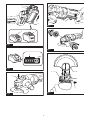
► Fig.3: 1. Shaft lock

15 ENGLISH
Switch action
CAUTION: Before installing the battery car-
tridge into the tool, always check to see that the
switch lever actuates properly and returns to the
"OFF" position when released.
CAUTION: For your safety, this tool is
equipped with lock-o lever which prevents the
tool from unintended starting. NEVER use the tool
if it runs when you simply pull the switch lever
without pulling the lock-o lever. Return the tool
to our authorized service center for proper repairs
BEFORE further usage.
CAUTION: Do not pull the switch lever hard
without pulling the lock-o lever. This can cause
switch breakage.
CAUTION: NEVER tape down or defeat pur-
pose and function of lock-o lever.
To prevent the switch lever from being accidentally
pulled, a lock-o lever is provided.
To start the tool, pull the lock-o lever toward the opera-
tor and then pull the switch lever.
To stop the tool, release the switch lever.
► Fig.4: 1. Lock-o lever 2. Switch lever
Accidental re-start preventive
function
When installing the battery cartridge while the switch is
ON, the tool does not start.
To start the tool, turn o the switch, and turn it on again.
Active Feedback sensing
Technology
The tool electronically detects situations where the
wheel or accessory may be at risk to be bound. In the
situation, the tool is automatically shut o to prevent
further rotation of the spindle (it does not prevent
kickback).
To restart the tool, switch o the tool rst, remove the
cause of sudden drop in the rotation speed, and then
turn the tool on.
Soft start feature
Soft start feature reduces starting reaction.
Electric brake
Electric brake is activated after the tool is switched o.
The brake does not work when the power supply is shut
down, such as the battery is removed accidentally, with
the switch still on.
ASSEMBLY
WARNING: Always be sure that the tool is
switched o and the battery cartridge is removed
before adjusting or checking function on the tool.
Installing side grip (handle)
CAUTION: Always be sure that the side grip is
installed securely before operation.
Screw the side grip securely on the position of the tool
as shown in the gure.
► Fig.5
Installing or removing wheel guard
WARNING:
When using a depressed center wheel,
ap disc, ex wheel or wire wheel brush, the wheel
guard must be tted on the tool so that the closed side
of the guard always points toward the operator.
WARNING: Make sure that the wheel guard is
securely locked by the lock lever with one of the
holes on the wheel guard.
WARNING: When using an abrasive cut-o
/ diamond wheel, be sure to use only the special
wheel guard designed for use with cut-o wheels.
For depressed center wheel, ap disc,
ex wheel, wire wheel brush / abrasive
cut-o wheel, diamond wheel
1. While pushing the lock lever, mount the wheel
guard with the protrusions on the wheel guard aligned
with the notches on the bearing box.
► Fig.6: 1. Lock lever 2. Notch 3. Protrusion
2.
While pushing the lock lever toward A, hold down
the portions B of the wheel guard as shown in the gure.
► Fig.7: 1. Wheel guard 2. Hole
NOTE: Push down the wheel guard straight.
Otherwise, you cannot secure the wheel guard.
3.
While pushing the lock lever toward A, rotate the wheel
guard toward C, and then, change the angle of the wheel
guard according to the work so that the operator can be pro-
tected. Align the lock lever with one of the holes in the wheel
guard, and then release the lock lever to lock the wheel guard.
► Fig.8: 1. Wheel guard 2. Hole
To remove wheel guard, follow the installation proce-
dure in reverse.
Clip-on cutting wheel guard attachment
Optional accessory
NOTE: For cutting-o operations, a clip-on cutting
wheel guard attachment can be used with the wheel
guard (for grinding wheel).
Not available in some countries.
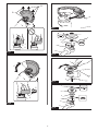
► Fig.9

16 ENGLISH
Installing or removing depressed
center wheel or ap disc
Optional accessory
WARNING: When using a depressed center
wheel or ap disc, the wheel guard must be tted
on the tool so that the closed side of the guard
always points toward the operator.
WARNING: Make sure that the mounting part
of the inner ange ts into the inner diameter of
the depressed center wheel / ap disc perfectly.
Mounting the inner ange on the wrong side may
result in the dangerous vibration.
Mount the inner ange onto the spindle.
Make sure to t the dented part of the inner ange onto
the straight part at the bottom of the spindle.
Fit the depressed center wheel / ap disc on the inner
ange and screw the lock nut onto the spindle.
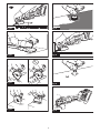
► Fig.10: 1. Lock nut 2. Depressed center wheel
3. Inner ange 4. Mounting part
To tighten the lock nut, press the shaft lock rmly so
that the spindle cannot revolve, then use the lock nut
wrench and securely tighten clockwise.
► Fig.11: 1. Lock nut wrench 2. Shaft lock
To remove the wheel, follow the installation procedure
in reverse.
Installing or removing ex wheel
Optional accessory
WARNING: Always use supplied guard when
ex wheel is on the tool. Wheel can shatter during
use and guard helps to reduce chances of personal
injury.
► Fig.12: 1. Lock nut 2. Flex wheel 3. Back up pad
4. Inner ange
Follow instructions for depressed center wheel but also
use back up pad over wheel.
Installing or removing abrasive disc
Optional accessory
NOTE: Use sander accessories specied in this man-
ual. These must be purchased separately.
For 100 mm (4″) model
► Fig.13: 1. Sanding lock nut 2. Abrasive disc
3. Rubber pad 4. Inner ange
1. Mount the inner ange onto the spindle.
2. Mount the rubber pad onto the spindle.
3. Fit the disc on the rubber pad and screw the sand-
ing lock nut onto the spindle.
4. Hold the spindle with the shaft lock, and securely
tighten the sanding lock nut clockwise with the lock nut
wrench.
To remove the disc, follow the installation procedure in
reverse.
For model other than 100 mm (4″)
► Fig.14: 1. Sanding lock nut 2. Abrasive disc
3. Rubber pad
1. Mount the rubber pad onto the spindle.
2. Fit the disc on the rubber pad and screw the sand-
ing lock nut onto the spindle.
3. Hold the spindle with the shaft lock, and securely
tighten the sanding lock nut clockwise with the lock nut
wrench.
To remove the disc, follow the installation procedure in
reverse.
Installing or removing Ezynut
Optional accessory
Only for tools with M14 spindle thread.
Mount inner ange, abrasive wheel and Ezynut onto the
spindle so that Makita Logo on Ezynut faces outside.
► Fig.15: 1. Ezynut 2. Abrasive wheel 3. Inner ange
4. Spindle
Press shaft lock rmly and tighten Ezynut by turning the
abrasive wheel clockwise as far as it turns.
► Fig.16: 1. Shaft lock
To loosen the Ezynut, turn the outside ring of Ezynut
counterclockwise.
NOTE: Ezynut can be loosened by hand as long
as the arrow points the notch. Otherwise a lock nut
wrench is required to loosen it. Insert one pin of the
wrench into a hole and turn Ezynut counterclockwise.
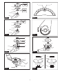
► Fig.17: 1. Arrow 2. Notch
► Fig.18
Installing abrasive cut-o / diamond
wheel
Optional accessory
WARNING: When using an abrasive cut-o
/ diamond wheel, be sure to use only the special
wheel guard designed for use with cut-o wheels.
WARNING: NEVER use cut-o wheel for side
grinding.
CAUTION: When installing the diamond
wheel, be sure to align the direction of the arrow
on the wheel with the arrow on the tool.
► Fig.19: 1. Lock nut 2. Abrasive cut-o wheel / dia-
mond wheel 3. Inner ange 4. Wheel guard
for abrasive cut-o wheel / diamond wheel
As for the installation, follow the instructions for
depressed center wheel.
The direction for mounting the lock nut and the inner
ange varies by wheel type and thickness.

17 ENGLISH
Refer to the following gures.
For 100 mm (4″) model
When installing the abrasive cut-o wheel:
► Fig.20: 1. Lock nut 2. Abrasive cut-o wheel
(Thinner than 4 mm (5/32")) 3. Abrasive cut-
o wheel (4 mm (5/32") or thicker) 4. Inner
ange
When installing the diamond wheel:
► Fig.21: 1. Lock nut 2. Diamond wheel (Thinner than
4 mm (5/32″)) 3. Diamond wheel (4 mm
(5/32″) or thicker) 4. Inner ange
For model other than 100 mm (4″)
When installing the abrasive cut-o wheel:
► Fig.22: 1. Lock nut 2. Abrasive cut-o wheel
(Thinner than 4 mm (5/32")) 3. Abrasive cut-
o wheel (4 mm (5/32") or thicker) 4. Inner
ange
When installing the diamond wheel:
► Fig.23: 1. Lock nut 2. Diamond wheel (Thinner than
4 mm (5/32″)) 3. Diamond wheel (4 mm
(5/32″) or thicker) 4. Inner ange
Installing wire cup brush
Optional accessory
CAUTION: Do not use wire cup brush that
is damaged, or which is out of balance. Use of
damaged wire cup brush could increase potential for
injury from contact with broken brush wires.
Place the tool upside down to allow easy access to the
spindle.
Remove any accessories on spindle. Thread wire cup
brush onto spindle and tighten with supplied wrench.
► Fig.24: 1. Wire cup brush
Installing wire wheel brush
Optional accessory
CAUTION: Do not use wire wheel brush that
is damaged, or which is out of balance. Use of
damaged wire wheel brush could increase potential
for injury from contact with broken wires.
CAUTION: ALWAYS use guard with wire
wheel brushes, assuring diameter of wheel ts
inside guard. Wheel can shatter during use and
guard helps to reduce chances of personal injury.
Place the tool upside down to allow easy access to the
spindle.
Remove any accessories on spindle. Thread wire wheel
brush onto spindle and tighten with the wrenches.
► Fig.25: 1. Wire wheel brush
Installing hole cutter
Optional accessory
Place the tool upside down to allow easy access to the
spindle.
Remove any accessories on the spindle. Thread the
hole cutter onto the spindle, and tighten it with the sup-
plied wrench.
► Fig.26: 1. Hole cutter
Installing dust collecting wheel
guard for grinding
Only for model GA049G / GA050G
Optional accessory
With optional accessories, you can use this tool for
planing concrete surface.
CAUTION: Dust collecting wheel guard for
grinding is only for use in planing concrete sur-
face with a cup-type diamond wheel. Do not use
this guard with any other cutting accessory or for
any other purpose.
CAUTION: Before operation, make sure that
a vacuum cleaner is connected to the tool and
turned on.
Place the tool upside down and install the dust collect-
ing wheel guard.
Mount the inner ange onto the spindle.
Fit the cup-type diamond wheel on the inner ange and
tighten the lock nut onto the spindle.
► Fig.27: 1. Lock nut 2. Cup-type diamond wheel
3. Hubbed cup-type diamond wheel 4. Inner
ange 5. Dust collecting wheel guard
6. Bearing box
NOTE: For information how to install the dust col-
lecting wheel guard, refer to the manual of the dust
collecting wheel guard.
Installing dust collecting wheel
guard for cutting-o
Only for model GA048G / GA049G / GA050G
Optional accessory
With optional accessories, you can use this tool for
cutting stone materials.
► Fig.28
NOTE: For information how to install the dust col-
lecting wheel guard, refer to the manual of the dust
collecting wheel guard.

18 ENGLISH
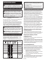
OPERATION
WARNING: It should never be necessary to
force the tool. The weight of the tool applies ade-
quate pressure. Forcing and excessive pressure
could cause dangerous wheel breakage.
WARNING: ALWAYS replace wheel if tool is
dropped while grinding.
WARNING: NEVER hit the workpiece with the
wheel.
WARNING: Avoid bouncing and snagging
the wheel, especially when working corners,
sharp edges etc. This can cause loss of control and
kickback.
WARNING: NEVER use tool with wood cutting
blades and other saw blades. Such blades when
used on a grinder frequently kick and cause loss of
control leading to personal injury.
CAUTION: Never switch on the tool when it
is in contact with the workpiece, it may cause an
injury to operator.
CAUTION: Always wear safety goggles or a
face shield during operation.
CAUTION: After operation, always switch o
the tool and wait until the wheel has come to a
complete stop before putting the tool down.
CAUTION: ALWAYS hold the tool rmly with
one hand on housing and the other on the side
grip (handle).
NOTE: A dual purpose wheel can be used for both
grinding and cutting-o operations.
Refer to the "Grinding and sanding operation" for
grinding operation, and refer to the "Operation with
abrasive cut-o / diamond wheel" for cutting-o
operation.
Grinding and sanding operation
► Fig.29
Turn the tool on and then apply the wheel or disc to the
workpiece.
In general, keep the edge of the wheel or disc at an
angle of about 15° to the workpiece surface.
During the break-in period with a new wheel, do not
work the grinder in forward direction or it may cut into
the workpiece. Once the edge of the wheel has been
rounded o by use, the wheel may be worked in both
forward and backward direction.
Usage example: operation with cup-type diamond
wheel
► Fig.30
Keep the tool horizontally and apply the entire cup-type
diamond wheel to the workpiece surface.
Operation with abrasive cut-o /
diamond wheel
Optional accessory
WARNING: Do not "jam" the wheel or apply
excessive pressure. Do not attempt to make an
excessive depth of cut. Overstressing the wheel
increases the loading and susceptibility to twisting
or binding of the wheel in the cut and the possibility
of kickback, wheel breakage and overheating of the
motor may occur.
WARNING: Do not start the cutting operation
in the workpiece. Let the wheel reach full speed
and carefully enter into the cut moving the tool
forward over the workpiece surface. The wheel
may bind, walk up or kickback if the power tool is
started in the workpiece.
WARNING: During cutting operations, never
change the angle of the wheel. Placing side pres-
sure on the cut-o wheel (as in grinding) will cause
the wheel to crack and break, causing serious per-
sonal injury.
WARNING: A diamond wheel shall be oper-
ated perpendicular to the material being cut.
Usage example: operation with abrasive cut-o
wheel
► Fig.31
Usage example: operation with diamond wheel
► Fig.32
Operation with wire cup brush
Optional accessory
CAUTION: Check operation of wire cup brush
by running tool with no load, insuring that no one
is in front of or in line with wire cup brush.
NOTICE: Avoid applying too much pressure
which causes over bending of wires when using
the wire cup brush. It may lead to premature
breakage.
Usage example: operation with wire cup brush
► Fig.33
Operation with wire wheel brush
Optional accessory
CAUTION: Check operation of wire wheel
brush by running tool with no load, insuring that
no one is in front of or in line with the wire wheel
brush.
NOTICE: Avoid applying too much pressure
which causes over bending of wires when
using wire wheel brush. It may lead to premature
breakage.
Usage example: operation with wire wheel brush
► Fig.34

19 ENGLISH
Operation with hole cutter
Optional accessory
CAUTION: Check operation of the hole cutter
by running the tool with no load, insuring that no
one is in front of the hole cutter.
NOTICE: Do not tilt the tool during operation. It
may lead to premature breakage.
Usage example: operation with hole cutter
► Fig.35
MAINTENANCE
WARNING: Always be sure that the tool is
switched o and the battery cartridge is removed
before attempting to perform inspection or
maintenance.
NOTICE: Never use gasoline, benzine, thinner,
alcohol or the like. Discoloration, deformation or
cracks may result.
To maintain product SAFETY and RELIABILITY,
repairs, any other maintenance or adjustment should
be performed by Makita Authorized or Factory Service
Centers, always using Makita replacement parts.
Air vent cleaning
The tool and its air vents have to be kept clean.
Regularly clean the tool's air vents or whenever the
vents start to become obstructed.
► Fig.36: 1. Exhaust vent 2. Inhalation vent
Remove the dust cover from inhalation vent and clean it
for smooth air circulation.
► Fig.37: 1. Dust cover
NOTICE: Clean out the dust cover when it is
clogged with dust or foreign matters. Continuing
operation with a clogged dust cover may damage the
tool.

20 ENGLISH
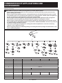
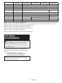
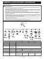
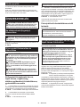
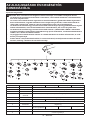
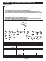
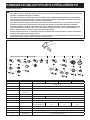
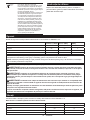
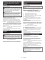
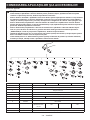
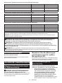
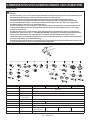
COMBINATION OF APPLICATIONS AND
ACCESSORIES
Optional accessory
CAUTION: Using the tool with incorrect guards can cause risks as follows.
• When using a cut-o wheel guard for facial grinding, the wheel guard may interfere with the work-
piece causing poor control.
• When using a grinding wheel guard for cutting-o operations with bonded abrasive wheels and dia-
mond wheels, there is an increased risk of exposure to rotating wheels, emitted sparks and particles,
as well as exposure to wheel fragments in the event of wheel burst.
• When using a cut-o wheel guard or grinding wheel guard for facial operations with cup-type dia-
mond wheels, the wheel guard may interfere with the workpiece causing poor control.
• When using a cut-o wheel guard or grinding wheel guard with a wheel-type wire brush with a thick-
ness greater than the maximum thickness as specied in "SPECIFICATIONS", the wires may catch on
the guard leading to breaking of wires.
• Use of dust collecting wheel guards for cutting-o and facial operations in concrete or masonry
reduces a risk of exposure to dust.
• When using dual purpose (combined grinding and cutting-o abrasive) ange mounted wheels, only
use a cut-o wheel guard.
1
2
5
22
11
12
4
3
7
9
10
13
33
14 2
17
3
16
15
16
17
19
20
3
21
3
18
22
6
5
56
56
5656
8
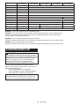
-Application 100 mm model 115 mm model 125 mm model 150 mm model
1 - Side grip
2 - Wheel guard (for grinding wheel)
3 - Inner ange
4Grinding / Sanding Depressed center wheel / Flap disc
5 - Lock nut
6 - - Ezynut *1
7 - Back up pad
8Grinding Flex wheel
9 - Inner ange and
rubber pad 76 Rubber pad 100 Rubber pad 115 Rubber pad 125
10 Sanding Abrasive disc
11 -Sanding lock nut
12 Wire brushing Wire wheel brush
Pagina se încarcă...
Pagina se încarcă...
Pagina se încarcă...
Pagina se încarcă...
Pagina se încarcă...
Pagina se încarcă...
Pagina se încarcă...
Pagina se încarcă...
Pagina se încarcă...
Pagina se încarcă...
Pagina se încarcă...
Pagina se încarcă...
Pagina se încarcă...
Pagina se încarcă...
Pagina se încarcă...
Pagina se încarcă...
Pagina se încarcă...
Pagina se încarcă...
Pagina se încarcă...
Pagina se încarcă...
Pagina se încarcă...
Pagina se încarcă...
Pagina se încarcă...
Pagina se încarcă...
Pagina se încarcă...
Pagina se încarcă...
Pagina se încarcă...
Pagina se încarcă...
Pagina se încarcă...
Pagina se încarcă...
Pagina se încarcă...
Pagina se încarcă...
Pagina se încarcă...
Pagina se încarcă...
Pagina se încarcă...
Pagina se încarcă...
Pagina se încarcă...
Pagina se încarcă...
Pagina se încarcă...
Pagina se încarcă...
Pagina se încarcă...
Pagina se încarcă...
Pagina se încarcă...
Pagina se încarcă...
Pagina se încarcă...
Pagina se încarcă...
Pagina se încarcă...
Pagina se încarcă...
Pagina se încarcă...
Pagina se încarcă...
Pagina se încarcă...
Pagina se încarcă...
Pagina se încarcă...
Pagina se încarcă...
Pagina se încarcă...
Pagina se încarcă...
Pagina se încarcă...
Pagina se încarcă...
Pagina se încarcă...
Pagina se încarcă...
Pagina se încarcă...
Pagina se încarcă...
Pagina se încarcă...
Pagina se încarcă...
Pagina se încarcă...
Pagina se încarcă...
Pagina se încarcă...
Pagina se încarcă...
Pagina se încarcă...
Pagina se încarcă...
Pagina se încarcă...
Pagina se încarcă...
Pagina se încarcă...
Pagina se încarcă...
Pagina se încarcă...
Pagina se încarcă...
Pagina se încarcă...
Pagina se încarcă...
Pagina se încarcă...
Pagina se încarcă...
Pagina se încarcă...
Pagina se încarcă...
Pagina se încarcă...
Pagina se încarcă...
Pagina se încarcă...
Pagina se încarcă...
Pagina se încarcă...
Pagina se încarcă...
Pagina se încarcă...
Pagina se încarcă...
Pagina se încarcă...
Pagina se încarcă...
Pagina se încarcă...
Pagina se încarcă...
Pagina se încarcă...
Pagina se încarcă...
Pagina se încarcă...
Pagina se încarcă...
Pagina se încarcă...
Pagina se încarcă...
Pagina se încarcă...
Pagina se încarcă...
Pagina se încarcă...
Pagina se încarcă...
Pagina se încarcă...
Pagina se încarcă...
Pagina se încarcă...
Pagina se încarcă...
-
 1
1
-
 2
2
-
 3
3
-
 4
4
-
 5
5
-
 6
6
-
 7
7
-
 8
8
-
 9
9
-
 10
10
-
 11
11
-
 12
12
-
 13
13
-
 14
14
-
 15
15
-
 16
16
-
 17
17
-
 18
18
-
 19
19
-
 20
20
-
 21
21
-
 22
22
-
 23
23
-
 24
24
-
 25
25
-
 26
26
-
 27
27
-
 28
28
-
 29
29
-
 30
30
-
 31
31
-
 32
32
-
 33
33
-
 34
34
-
 35
35
-
 36
36
-
 37
37
-
 38
38
-
 39
39
-
 40
40
-
 41
41
-
 42
42
-
 43
43
-
 44
44
-
 45
45
-
 46
46
-
 47
47
-
 48
48
-
 49
49
-
 50
50
-
 51
51
-
 52
52
-
 53
53
-
 54
54
-
 55
55
-
 56
56
-
 57
57
-
 58
58
-
 59
59
-
 60
60
-
 61
61
-
 62
62
-
 63
63
-
 64
64
-
 65
65
-
 66
66
-
 67
67
-
 68
68
-
 69
69
-
 70
70
-
 71
71
-
 72
72
-
 73
73
-
 74
74
-
 75
75
-
 76
76
-
 77
77
-
 78
78
-
 79
79
-
 80
80
-
 81
81
-
 82
82
-
 83
83
-
 84
84
-
 85
85
-
 86
86
-
 87
87
-
 88
88
-
 89
89
-
 90
90
-
 91
91
-
 92
92
-
 93
93
-
 94
94
-
 95
95
-
 96
96
-
 97
97
-
 98
98
-
 99
99
-
 100
100
-
 101
101
-
 102
102
-
 103
103
-
 104
104
-
 105
105
-
 106
106
-
 107
107
-
 108
108
-
 109
109
-
 110
110
-
 111
111
-
 112
112
-
 113
113
-
 114
114
-
 115
115
-
 116
116
-
 117
117
-
 118
118
-
 119
119
-
 120
120
-
 121
121
-
 122
122
-
 123
123
-
 124
124
-
 125
125
-
 126
126
-
 127
127
-
 128
128


Makita GA048G Manual de utilizare
- Categorie
- Unelte electrice
- Tip
- Manual de utilizare
în alte limbi
- slovenčina: Makita GA048G Používateľská príručka
- polski: Makita GA048G Instrukcja obsługi
Lucrări înrudite
-
Makita BGA450 Manual de utilizare
-
-
Makita GA042G Manual de utilizare
-
Makita DMC300 Manual de utilizare
-
Makita GA037G Manual de utilizare
-
-
Makita GA027G Manual de utilizare
-
Makita GA021G Manual de utilizare
-
Makita DGA411 Manual de utilizare