
DMC300
EN Cordless Compact Cut O INSTRUCTION MANUAL 8
PL Akumulatorowa Przecinarka
Kątowa INSTRUKCJA OBSŁUGI 17
HU Akkumulátoros kompakt
gyorsdaraboló HASZNÁLATI KÉZIKÖNYV 27
SK Akumulátorová kompaktná
rozbrusovačka NÁVOD NA OBSLUHU 37
CS Akumulátorová kompaktní
řezačka NÁVOD K OBSLUZE 46
UK Бездротова компактна
відрізна пила ІНСТРУКЦІЯ З
ЕКСПЛУАТАЦІЇ 55
RO Mașină de debitat compactă
fără cablu MANUAL DE INSTRUCŢIUNI 65
DE Akku-Winkelschleifer BETRIEBSANLEITUNG 75

2
1
2
3
Fig.1
1
2
Fig.2
1
2
Fig.3
1
Fig.4
1
2
1
2
1
Fig.5
1
2
1
1
2
Fig.6
1
2
Fig.7

3
1
2
Fig.8
1
Fig.9
1
Fig.10
1
3
2
Fig.11
1
3
2
3
Fig.12

4
1
2
3
4
Fig.13
1
Fig.14
1
2
3
4
5
Fig.15
1
2
3
4
5
Fig.16
1
2
3
Fig.17
1
Fig.18

5
12
3
4
Fig.19
1
2
Fig.20
2
1
Fig.21
1
2
3
Fig.22
1
2
3
4
5
Fig.23
1
2
Fig.24

6
1
2
Fig.25
Fig.26
Fig.27
Fig.28
Fig.29

7
12
Fig.30
1
2
Fig.31

8ENGLISH
ENGLISH (Original instructions)
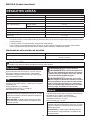
SPECIFICATIONS
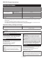
Model: DMC300
Wheel outer diameter 76 mm
Wheel inner (arbor) diameter 10.0 mm / 9.5 mm (3/8″) (country specic)
Max. wheel thickness 1.0 mm
Max. cutting capacities With dust collect cover 13.5 mm
Without dust collect cover 16.0 mm
Rated speed (n) / No load speed (n0)20,000 min-1
Overall length 271 mm *1
Rated voltage D.C. 18 V
Net weight 1.2 - 1.7 kg
*1. With battery cartridge (BL1860B) / Without dust collection cover
• Due to our continuing program of research and development, the specications herein are subject to change
without notice.
• Specications and battery cartridge may dier from country to country.
• The weight may dier depending on the attachment(s), including the battery cartridge. The lightest and heavi-
est combinations, according to EPTA-Procedure 01/2014, are shown in the table.
Applicable battery cartridge and charger
Battery cartridge BL1815N / BL1820B / BL1830B / BL1840B / BL1850B / BL1860B
Charger DC18RC / DC18RD / DC18RE / DC18SD / DC18SE / DC18SF /
DC18SH / DC18WC
• Some of the battery cartridges and chargers listed above may not be available depending on your region of
residence.
WARNING: Only use the battery cartridges and chargers listed above. Use of any other battery cartridges
and chargers may cause injury and/or re.
Intended use
The tool is intended for cutting a sheet, tting, pipe, tile
or wall in metal, plastic, ceramic, plaster and similar
composite materials without use of water.
Noise
The typical A-weighted noise level determined accord-
ing to EN60745-2-22:
Sound pressure level (LpA) : 88 dB (A)
Sound power level (LWA) : 99 dB (A)
Uncertainty (K) : 3 dB (A)
NOTE: The declared noise emission value(s) has
been measured in accordance with a standard test
method and may be used for comparing one tool with
another.
NOTE: The declared noise emission value(s)
may also be used in a preliminary assessment of
exposure.
WARNING: Wear ear protection.
WARNING:
The noise emission during actual
use of the power tool can dier from the declared
value(s) depending on the ways in which the tool is
used especially what kind of workpiece is processed.
WARNING:
Be sure to identify safety measures
to protect the operator that are based on an estima-
tion of exposure in the actual conditions of use (tak-
ing account of all parts of the operating cycle such
as the times when the tool is switched o and when
it is running idle in addition to the trigger time).
Vibration
The vibration total value (tri-axial vector sum) deter-
mined according to EN60745-2-22:
Work mode: concrete cutting (thickness 5 mm)
Vibration emission (ah) : 3.0 m/s2
Uncertainty (K) : 1.5 m/s2
NOTE: The declared vibration total value(s) has been
measured in accordance with a standard test method
and may be used for comparing one tool with another.
NOTE: The declared vibration total value(s) may also
be used in a preliminary assessment of exposure.

9ENGLISH
WARNING: The vibration emission during
actual use of the power tool can dier from the
declared value(s) depending on the ways in which
the tool is used especially what kind of workpiece
is processed.
WARNING: Be sure to identify safety mea-
sures to protect the operator that are based on an
estimation of exposure in the actual conditions of
use (taking account of all parts of the operating
cycle such as the times when the tool is switched
o and when it is running idle in addition to the
trigger time).
Declarations of Conformity
For European countries only
The Declarations of conformity are included in Annex A
to this instruction manual.
SAFETY WARNINGS
General power tool safety warnings
WARNING Read all safety warnings, instruc-
tions, illustrations and specications provided with
this power tool. Failure to follow all instructions listed
below may result in electric shock, re and/or serious
injury.
Save all warnings and instruc-
tions for future reference.
The term "power tool" in the warnings refers to your
mains-operated (corded) power tool or battery-operated
(cordless) power tool.
Compact cut o safety warnings
1. The guard provided with the tool must be
securely attached to the power tool and
positioned for maximum safety, so the least
amount of wheel is exposed towards the oper-
ator. Position yourself and bystanders away
from the plane of the rotating wheel. The guard
helps to protect operator from broken wheel frag-
ments and accidental contact with wheel.
2. Use only bonded reinforced or diamond cut-o
wheels for your power tool. Just because an
accessory can be attached to your power tool, it
does not assure safe operation.
3. The rated speed of the accessory must be at
least equal to the maximum speed marked on
the power tool. Accessories running faster than
their rated speed can break and y apart.
4. Wheels must be used only for recommended
applications. For example: do not grind with
the side of cut-o wheel. Abrasive cut-o wheels
are intended for peripheral grinding, side forces
applied to these wheels may cause them to
shatter.
5. Always use undamaged wheel anges that are
of correct diameter for your selected wheel.
Proper wheel anges support the wheel thus
reducing the possibility of wheel breakage.
6. Do not use worn down reinforced wheels from
larger power tools. Wheels intended for a larger
power tool are not suitable for the higher speed of
a smaller tool and may burst.
7. The outside diameter and the thickness of your
accessory must be within the capacity rating
of your power tool. Incorrectly sized accessories
cannot be adequately guarded or controlled.
8. The arbour size of wheels and anges must
properly t the spindle of the power tool.
Wheels and anges with arbour holes that do not
match the mounting hardware of the power tool
will run out of balance, vibrate excessively and
may cause loss of control.
9. Do not use damaged wheels. Before each
use, inspect the wheels for chips and cracks.
If power tool or wheel is dropped, inspect for
damage or install an undamaged wheel. After
inspecting and installing the wheel, position
yourself and bystanders away from the plane
of the rotating wheel and run the power tool
at maximum no load speed for one minute.
Damaged wheels will normally break apart during
this test time.
10. Wear personal protective equipment. Always
wear hearing protection. Depending on
application, use face shield, safety goggles
or safety glasses. As appropriate, wear dust
mask, gloves and shop apron capable of stop-
ping small abrasive or workpiece fragments.
The eye protection must be capable of stopping
ying debris generated by various operations.
The dust mask or respirator must be capable of
ltrating particles generated by your operation.
Prolonged exposure to high intensity noise may
cause hearing loss.
11. Keep bystanders a safe distance away from
work area. Anyone entering the work area
must wear personal protective equipment.
Fragments of workpiece or of a broken wheel may
y away and cause injury beyond immediate area
of operation.
12. Hold the power tool by insulated gripping
surfaces only, when performing an operation
where the cutting accessory may contact hid-
den wiring. Cutting accessory contacting a “live”
wire may make exposed metal parts of the power
tool “live” and could give the operator an electric
shock.
13. Never lay the power tool down until the acces-
sory has come to a complete stop. The spinning
wheel may grab the surface and pull the power
tool out of your control.
14. Do not run the power tool while carrying it at
your side. Accidental contact with the spinning
accessory could snag your clothing, pulling the
accessory into your body.
15. Regularly clean the power tool’s air vents. The
motorʼs fan will draw the dust inside the housing
and excessive accumulation of powdered metal
may cause electrical hazards.

10 ENGLISH
16. Do not operate the power tool near ammable
materials. Sparks could ignite these materials.
17. Do not use accessories that require liquid
coolants. Using water or other liquid coolants
may result in electrocution or shock.
Kickback and related warnings
Kickback is a sudden reaction to a pinched or snagged
rotating wheel. Pinching or snagging causes rapid
stalling of the rotating wheel which in turn causes the
uncontrolled power tool to be forced in the direction
opposite of the wheel’s rotation at the point of the
binding.
For example, if an abrasive wheel is snagged or
pinched by the workpiece, the edge of the wheel that is
entering into the pinch point can dig into the surface of
the material causing the wheel to climb out or kick out.
The wheel may either jump toward or away from the
operator, depending on direction of the wheel’s move-
ment at the point of pinching. Abrasive wheels may also
break under these conditions.
Kickback is the result of power tool misuse and/or
incorrect operating procedures or conditions and can be
avoided by taking proper precautions as given below.
1. Maintain a rm grip on the power tool and
position your body and arm to allow you to
resist kickback forces. Always use auxiliary
handle, if provided, for maximum control over
kickback or torque reaction during start-up.
The operator can control torque reactions or kick-
back forces, if proper precautions are taken.
2. Never place your hand near the rotating acces-
sory. Accessory may kickback over your hand.
3. Do not position your body in line with the
rotating wheel. Kickback will propel the tool in
direction opposite to the wheel’s movement at the
point of snagging.
4. Use special care when working corners, sharp
edges etc. Avoid bouncing and snagging the
accessory. Corners, sharp edges or bouncing
have a tendency to snag the rotating accessory
and cause loss of control or kickback.
5. Do not attach a saw chain, woodcarving blade,
segmented diamond wheel with a peripheral
gap greater than 10 mm or toothed saw blade.
Such blades create frequent kickback and loss of
control.
6. Do not “jam” the wheel or apply excessive
pressure. Do not attempt to make an excessive
depth of cut. Overstressing the wheel increases
the loading and susceptibility to twisting or binding
of the wheel in the cut and the possibility of kick-
back or wheel breakage.
7. When wheel is binding or when interrupting
a cut for any reason, switch o the power
tool and hold the power tool motionless until
the wheel comes to a complete stop. Never
attempt to remove the wheel from the cut while
the wheel is in motion otherwise kickback may
occur. Investigate and take corrective action to
eliminate the cause of wheel binding.
8. Do not restart the cutting operation in the
workpiece. Let the wheel reach full speed and
carefully re-enter the cut. The wheel may bind,
walk up or kickback if the power tool is restarted in
the workpiece.
9. Support panels or any oversized workpiece to
minimize the risk of wheel pinching and kick-
back. Large workpieces tend to sag under their
own weight. Supports must be placed under the
workpiece near the line of cut and near the edge
of the workpiece on both sides of the wheel.
10. Use extra caution when making a “pocket cut”
into existing walls or other blind areas. The
protruding wheel may cut gas or water pipes, elec-
trical wiring or objects that can cause kickback.
11. Before using a segmented diamond wheel,
make sure that the diamond wheel has the
peripheral gap between segments of 10 mm or
less, only with a negative rake angle.
Additional Safety Warnings:
1. Never attempt to cut with the tool held upside
down in a vise. This can lead to serious acci-
dents, because it is extremely dangerous.
2. Check that the workpiece is properly
supported.
3. Some material contains chemicals which may
be toxic. Take caution to prevent dust inhala-
tion and skin contact. Follow material supplier
safety data.
4. Store wheels as per manufacturer recom-
mendations. Improper storage may damage the
wheels.
SAVE THESE INSTRUCTIONS.
WARNING: DO NOT let comfort or familiarity
with product (gained from repeated use) replace
strict adherence to safety rules for the subject
product. MISUSE or failure to follow the safety
rules stated in this instruction manual may cause
serious personal injury.
Important safety instructions for
battery cartridge
1. Before using battery cartridge, read all instruc-
tions and cautionary markings on (1) battery
charger, (2) battery, and (3) product using
battery.
2. Do not disassemble or tamper with the battery
cartridge. It may result in a re, excessive heat,
or explosion.
3. If operating time has become excessively
shorter, stop operating immediately. It may
result in a risk of overheating, possible burns
and even an explosion.
4. If electrolyte gets into your eyes, rinse them
out with clear water and seek medical atten-
tion right away. It may result in loss of your
eyesight.
5. Do not short the battery cartridge:
(1) Do not touch the terminals with any con-
ductive material.
(2) Avoid storing battery cartridge in a con-
tainer with other metal objects such as
nails, coins, etc.
(3) Do not expose battery cartridge to water
or rain.

11 ENGLISH
A battery short can cause a large current
ow, overheating, possible burns and even a
breakdown.
6. Do not store and use the tool and battery car-
tridge in locations where the temperature may
reach or exceed 50 °C (122 °F).
7. Do not incinerate the battery cartridge even if
it is severely damaged or is completely worn
out. The battery cartridge can explode in a re.
8. Do not nail, cut, crush, throw, drop the battery
cartridge, or hit against a hard object to the
battery cartridge. Such conduct may result in a
re, excessive heat, or explosion.
9. Do not use a damaged battery.
10. The contained lithium-ion batteries are subject
to the Dangerous Goods Legislation require-
ments.
For commercial transports e.g. by third parties,
forwarding agents, special requirement on pack-
aging and labeling must be observed.
For preparation of the item being shipped, consult-
ing an expert for hazardous material is required.
Please also observe possibly more detailed
national regulations.
Tape or mask o open contacts and pack up the
battery in such a manner that it cannot move
around in the packaging.
11. When disposing the battery cartridge, remove
it from the tool and dispose of it in a safe
place. Follow your local regulations relating to
disposal of battery.
12. Use the batteries only with the products
specied by Makita. Installing the batteries to
non-compliant products may result in a re, exces-
sive heat, explosion, or leak of electrolyte.
13. If the tool is not used for a long period of time,
the battery must be removed from the tool.
14. During and after use, the battery cartridge may
take on heat which can cause burns or low
temperature burns. Pay attention to the han-
dling of hot battery cartridges.
15. Do not touch the terminal of the tool imme-
diately after use as it may get hot enough to
cause burns.
16. Do not allow chips, dust, or soil stuck into the
terminals, holes, and grooves of the battery
cartridge. It may cause heating, catching re,
burst and malfunction of the tool or battery car-
tridge, resulting in burns or personal injury.
17. Unless the tool supports the use near
high-voltage electrical power lines, do not use
the battery cartridge near high-voltage electri-
cal power lines. It may result in a malfunction or
breakdown of the tool or battery cartridge.
18. Keep the battery away from children.
SAVE THESE INSTRUCTIONS.
CAUTION: Only use genuine Makita batteries.
Use of non-genuine Makita batteries, or batteries that
have been altered, may result in the battery bursting
causing res, personal injury and damage. It will
also void the Makita warranty for the Makita tool and
charger.
Tips for maintaining maximum
battery life
1. Charge the battery cartridge before completely
discharged. Always stop tool operation and
charge the battery cartridge when you notice
less tool power.
2. Never recharge a fully charged battery car-
tridge. Overcharging shortens the battery
service life.
3. Charge the battery cartridge with room tem-
perature at 10 °C - 40 °C (50 °F - 104 °F). Let
a hot battery cartridge cool down before
charging it.
4. When not using the battery cartridge, remove
it from the tool or the charger.
5. Charge the battery cartridge if you do not use
it for a long period (more than six months).
FUNCTIONAL
DESCRIPTION
CAUTION: Always be sure that the tool is
switched o and the battery cartridge is removed
before adjusting or checking function on the tool.
Installing or removing battery
cartridge
CAUTION: Always switch o the tool before
installing or removing of the battery cartridge.
CAUTION: Hold the tool and the battery car-
tridge rmly when installing or removing battery
cartridge. Failure to hold the tool and the battery
cartridge rmly may cause them to slip o your hands
and result in damage to the tool and battery cartridge
and a personal injury.
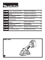
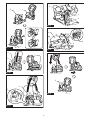
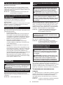
► Fig.1: 1. Red indicator 2. Button 3. Battery cartridge
To remove the battery cartridge, slide it from the tool
while sliding the button on the front of the cartridge.
To install the battery cartridge, align the tongue on the
battery cartridge with the groove in the housing and slip
it into place. Insert it all the way until it locks in place
with a little click. If you can see the red indicator as
shown in the gure, it is not locked completely.
CAUTION: Always install the battery cartridge
fully until the red indicator cannot be seen. If not,
it may accidentally fall out of the tool, causing injury to
you or someone around you.
CAUTION: Do not install the battery cartridge
forcibly. If the cartridge does not slide in easily, it is
not being inserted correctly.

12 ENGLISH
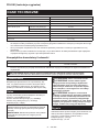
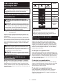
Indicating the remaining battery
capacity
Only for battery cartridges with the indicator
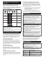
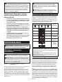
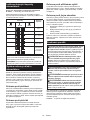
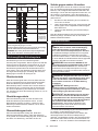
► Fig.2: 1. Indicator lamps 2. Check button
Press the check button on the battery cartridge to indi-
cate the remaining battery capacity. The indicator lamps
light up for a few seconds.
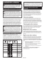
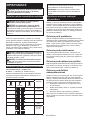
Indicator lamps Remaining
capacity
Lighted O Blinking
75% to 100%
50% to 75%
25% to 50%
0% to 25%
Charge the
battery.
The battery
may have
malfunctioned.
NOTE: Depending on the conditions of use and the
ambient temperature, the indication may dier slightly
from the actual capacity.
NOTE: The rst (far left) indicator lamp will blink when
the battery protection system works.
Tool / battery protection system
The tool is equipped with a tool/battery protection sys-
tem. This system automatically cuts o power to the
motor to extend tool and battery life. The tool will auto-
matically stop during operation if the tool or battery is
placed under one of the following conditions.
Overload protection
When the tool/battery is operated in a manner that
causes it to draw an abnormally high current, the tool
stops automatically and the operation lamp will blink. In
this situation, turn the tool o and stop the application
that caused the tool to become overloaded. Then turn
the tool on to restart.
Overheat protection
When the tool/battery is overheated, the tool stops
automatically and the operation lamp will blink. In this
situation, let the tool cool down before turning the tool
on again.
Overdischarge protection
When the battery capacity becomes low, the tool stops
automatically. If the tool does not run along with the
switch operation, remove the battery from the tool and
charge it.
Protections against other causes
Protection system is also designed for other causes
that could damage the tool and allows the tool to stop
automatically. Take all the following steps to clear the
causes, when the tool has been brought to a temporary
halt or stop in operation.
1.
Turn the tool o, and then turn it on again to restart.
2. Charge the battery(ies) or replace it/them with
recharged battery(ies).
3. Let the tool and battery(ies) cool down.
If no improvement can be found by restoring protection
system, then contact your local Makita Service Center.
Switch action
WARNING: NEVER use the tool if it runs when
you simply pull the switch trigger without press-
ing the lock-o button. A switch in need of repair
may result in unintentional operation and serious
personal injury. Return tool to a Makita service center
for proper repairs BEFORE further usage.
WARNING: NEVER defeat the lock-o button
by taping down or some other means. A switch with
a negated lock-o button may result in unintentional
operation and serious personal injury.
CAUTION: Before installing the battery car-
tridge into the tool, always check to see that the
switch trigger actuates properly and returns to
the "OFF" position when released.
CAUTION: Do not pull the switch trigger hard
without pressing in the lock-o button. This can
cause switch breakage.
CAUTION: The tool starts to brake the wheel
rotation immediately after you release the switch
trigger. Hold the tool rmly to respond the reac-
tion of the brake when releasing the switch trig-
ger. Sudden reaction can drop the tool o your hand
and can cause a personal injury.
To prevent the switch trigger from being accidentally
pulled, a lock-o button is provided. To start the tool,
press and hold the lock-o button, and then pull the
switch trigger. Release the switch trigger to stop.
► Fig.3: 1. Switch trigger 2. Lock-o button
Wheel selection
CAUTION: The outside diameter, thickness
and rated speed of your accessory must be within
the capacity rating of your power tool.
CAUTION: Wheels must be used only for
recommended applications.
Select one of the most appropriate types of cutting
wheels according to your application.
Wheel type Practical applications
Cut o wheel Cutting steel, stainless steel, metals
Tungsten carbide
grit wheel
Cutting plastics, plaster, composite
materials
Diamond Wheel Cutting tiles, ceramics

13 ENGLISH
Wheel rotation direction
CAUTION: Always check the direction of
rotation before operation.
CAUTION: Use the reversing switch only after
the tool comes to a complete stop. A sudden switch
in rotation direction during operation brings the tool to
a sharp stop for safety reasons.
Wheel rotation can be changed in either forward or
reverse direction.
To set the forward rotation, slide the reversing switch to
the left until “F” indication appears on the switch.
To select the reverse rotation, slide the reversing switch
to the right until “R” indication appears on the switch.
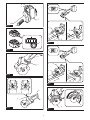
► Fig.4: 1. Reversing switch
Chips, debris, sparks, and cutting particles tend to y
o along a tangent direction of the wheel rotation. Use
the wheel guard eectively to avoid continued exposure
towards cut-o particles so it can discharge some of
cutting dust and particles into an alternative direction.
A reaction to a rapid stalling of the rotating wheel could make the
tool uncontrolled in the direction opposite to the wheel rotation.
Forward rotation
► Fig.5: 1. Cut-o particles 2. Reactions
Reverse rotation
► Fig.6: 1. Cut-o particles 2. Reactions
Wheel guard
CAUTION: Make sure that the wheel guard is
correctly and rmly positioned behind the cutting
wheel before operation.
Secure the wheel guard in a comfortable position, for maxi-
mum safety and minimum exposure to possible risk factors,
according to your work conditions and preferences.
Positioning forwards
► Fig.7: 1. Wheel guard 2. Cutting wheel
Positioning backwards
► Fig.8: 1. Wheel guard 2. Cutting wheel
Shaft lock
Press the shaft lock to prevent spindle rotation when
installing and removing a cutting wheel.
► Fig.9: 1. Shaft lock
NOTICE: Never actuate the shaft lock when the
spindle is moving. The tool may be damaged.
Operation lamp
CAUTION: Do not look in the light or see the
source of light directly.
To turn on the operation lamp, press and hold the lock-
o button and pull the switch trigger.
The lamp goes out approximately 15 seconds after
releasing the switch trigger.
► Fig.10: 1. Operation lamp
NOTICE: When the tool is operated with exces-
sive load, the operation lamp ashes. In this situ-
ation, release the switch trigger, and then reduce
the load on the tool before operating again.
NOTICE: When the tool is overheated, the opera-
tion lamp ashes. In this case, release the switch
trigger, and then cool down the tool/battery before
operating again.
NOTE: Use a dry cloth to wipe the dirt o the lens of
the lamp. Be careful not to scratch the lens of lamp, or
it may lower the illumination.
Adjusting depth of cut
CAUTION: After adjusting the depth of cut,
always tighten the thumb screw securely.
With the dust collection cover installed, ne adjustments
in the cutting depth can be made up to 13.5 mm.
Loosen the thumb screw on the depth scale. Lift or
lower the tool handle into position to align the depth
indicators on the cover with your desired cutting depth
on the scale. Then tightening the thumb screw.
► Fig.11: 1. Thumb screw 2. Depth scale 3. Depth
indicator
CAUTION: For clean and safe cutting, set the
cutting depths so that a cutting wheel overpasses the
undersurface of workpiece by 2.0 mm or less. Setting
in proper cutting depths helps to reduce potential
for dangerous kickbacks which may cause personal
injury.
Sighting for straight cutting
With the dust collection cover installed, straight cut
operation can safely be performed by aligning the cut-
ting wheel toward the cutting direction before the actual
cut operation.
Align the guide notch in the base of dust collection
cover with your intended cutting line on the workpiece.
► Fig.12: 1. Guide notch 2. Base 3. Cutting line
Connecting a vacuum cleaner
Optional accessory
When you wish to perform clean cutting operation,
connect a Makita vacuum cleaner to the dust nozzle in
the dust collection cover using a front cus 22 (optional
accessory).
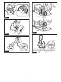
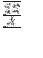
► Fig.13: 1. Front cus 22 2. Dust nozzle 3. Hose
4. Vacuum cleaner
Accidental re-start preventive
function
When installing the battery cartridge while pulling the
switch trigger, the tool will not start.
To start the tool, release the switch trigger rst. Press
and hold the lock-o button, and then pull the switch
trigger.

14 ENGLISH
Electronic function
The tool is equipped with the electronic functions for
easy operation.
• Electric brake
This tool is equipped with an electric brake. If the
tool consistently fails to quickly cease to function
after the switch trigger is released, have the tool
serviced at a Makita service center.
• Constant speed control
The speed control function provides the constant
rotation speed regardless of load conditions.
• Active Feedback sensing Technology
The tool electronically detects situations in which
the cutting wheel may be at risk to be bound.
In the situation, the tool automatically stops to
prevent further rotation of the spindle (it does not
prevent kickback).
In this case, release the switch trigger rst,
remove the cause of sudden drop in the rotation
speed, and then pull the switch trigger to restart
the tool.
ASSEMBLY
CAUTION: Always be sure that the tool is
switched o and the battery cartridge is removed
before carrying out any work on the tool.
Hex wrench storage
When not in use, store the hex wrench as shown in the
gure to keep it from being lost.
► Fig.14: 1. Hex wrench
Removing and installing cutting wheel
CAUTION: Use only the Makita hex wrench
supplied to remove and install a cutting wheel.
CAUTION: When installing a cutting wheel, be
sure to tighten the bolt securely.
NOTICE: When installing a diamond wheel for
its best performance, always make sure that the
arrows on the diamond wheel point in the same
direction as your desired wheel rotation.
To remove a cutting wheel, press the shaft lock fully so
that the cutting wheel cannot revolve and use the hex
wrench to loosen the hex bolt counterclockwise. Then
remove the hex bolt, outer ange and cutting wheel.
► Fig.15: 1. Shaft lock 2. Hex wrench 3. Hex bolt
4. Loosen 5. Tighten
NOTICE: If the inner ange is removed, place
it back onto the spindle with its wheel mounting
part facing upwards.
To install a cutting wheel, follow the removal procedure
in reverse.
► Fig.16: 1. Hex bolt 2. Outer ange 3. Cutting wheel
4. Inner ange 5. Spindle
Installing and removing dust
collection cover
CAUTION: Make sure that the wheel guard
is securely locked by the stopper inside the dust
collection cover before operation.
CAUTION: Avoid using the dust collection
cover for metalwork which creates heats and y-
ing sparks as it may melt the plastic components
of the dust collection cover.
The dust collection cover enhances safe and ecient
cutting operation, providing a safeguard against rotat-
ing wheel, cutting stability, precise control over cutting
depth, and dust extraction solutions, especially at tile,
plaster, stoneware cuttings.
Installing dust collection cover
1. Loosen the thumb screw on the depth scale of the
dust collection cover. Lift the cover fully up, and then
tighten the thumb screw to secure the dust collection
cover in a raised position.
► Fig.17: 1. Thumb screw 2. Depth scale 3. Dust
collection cover
2. Set the wheel guard on the tool in a forward
position.
► Fig.18: 1. Wheel guard
3. Raise the tool handle slightly and place the front
half of the wheel guard at an angle into the dust col-
lection cover, throwing the bottom of the cutting wheel
down through the wheel slot in the base.
► Fig.19: 1. Wheel guard 2. Dust collection cover
3. Cutting wheel 4. Wheel slot
4. Install the rear half of the wheel guard in the dust
collection cover, while lowering the tool handle from a
raised position to a down position.
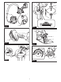
► Fig.20: 1. Wheel guard 2. Dust collection cover
5. Raise the tool handle again to hook the rear edge
of the wheel guard over the stopper inside the dust
collection cover.
► Fig.21: 1. Wheel guard 2. Stopper
6. Loosen the thumb screw. Swing the tool up and
down at your desired cutting depth. Then tighten the
thumb screw to secure the tool in place.
Removing dust collection cover
1. Loosen the thumb screw on the depth scale of the
dust collection cover. Lift the tool handle fully up, and
then tighten the thumb screw to secure the dust collec-
tion cover in a raised position.
► Fig.22: 1. Thumb screw 2. Depth scale 3. Dust
collection cover
2. Slide the release lever towards the thumb screw to
unlock the wheel guard from the stopper inside the dust
collection cover.
► Fig.23: 1. Release lever 2. Thumb screw 3. Wheel
guard 4. Dust collection cover 5. Stopper

15 ENGLISH
3. Dismount the rear half of the wheel guard from
the dust collection cover, while lowering the tool handle
from a raised position to a down position.
► Fig.24: 1. Wheel guard 2. Dust collection cover
4. Pull the front half of the wheel guard, at a slight
upward and outward angle, apart from the dust collec-
tion cover.
► Fig.25: 1. Wheel guard 2. Dust collection cover
OPERATION
CAUTION: Always maintain a rm grip on the
tool during operation.
CAUTION: Do not force the tool. Forcing and
exerting excessive pressure or allowing the wheel to
bend, pinch or twist in the cut can cause overheating
of the motor and dangerous kickback of the tool.
CAUTION: When cutting plastics, be sure not
to overheat the cutting wheel. It may result in melt-
ing the workpiece.
CAUTION: Do not bang or bump a cutting
wheel when starting or during operation.
CAUTION: Always wear safety goggles or a
face shield during operation.
CAUTION: After operation, always switch o
the tool and wait until the wheel has come to a
complete stop before putting the tool down.
Down cutting
NOTICE: Exercise due care about using an eec-
tive cutting surface of the wheel so as to avoid
exposure towards cut-o particles.
NOTICE: Keep a cutting wheel stand straight in
workpiece and avoid tilting or swinging the tool
during operation.
Position the wheel guard correctly to provide maximum
protection from sparks and loose particles thrown from
the cutting wheel. Place the tool over workpiece without
the cutting wheel making any contact. Turn the tool on
and wait until the cutting wheel attains full speed. Then
slowly lower the tool over the workpiece surface, using
a moderate feed suited to your applications.
Forward rotation
► Fig.26
Reverse rotation
► Fig.27
Straight cutting
CAUTION: Be sure that a cutting wheel
always works in an up-grinding motion. It other-
wise may cause the tool to be pushed uncontrolled
out of the cut.
NOTICE: Keep your cutting line straight and
apply steady pressure to obtain a uniform cut
through workpiece.
Set the base plate of dust collection cover on workpiece
to be cut without the cutting wheel making any contact.
Turn the tool on and wait until the cutting wheel attains
full speed. Then slowly move the tool over the work-
piece surface, keeping it at and advancing smoothly
until the cutting is completed.
Select the reverse rotation for push cutting, and the
forward rotation for pull cutting.
Push cutting in reverse rotation
► Fig.28
Pull cutting in forward rotation
► Fig.29
NOTE: Be aware that the dust collection cover tends
to function less eectively in pull cutting as some
cutting particles spread inside the cover against the
dust extraction ow.
MAINTENANCE
CAUTION: Always be sure that the tool is
switched o and the battery cartridge is removed
before attempting to perform inspection or
maintenance.
NOTICE: Never use gasoline, benzine, thinner,
alcohol or the like. Discoloration, deformation or
cracks may result.
To maintain product SAFETY and RELIABILITY,
repairs, any other maintenance or adjustment should
be performed by Makita Authorized or Factory Service
Centers, always using Makita replacement parts.
Dressing diamond wheel
If the cutting action of the diamond wheel begins to
diminish, use an old discarded coarse grit bench grinder
wheel or concrete block to dress the diamond wheel. To
do this, tightly secure the bench grinder wheel or con-
crete block and cut in it.
After use
Clean the dust inside the tool by running the tool at an
idle for a while. Accumulation of dust in the motor may
cause a malfunction of the tool.

16 ENGLISH
Cleaning wheel guard and dust
collection cover
Clean inside the wheel guard and dust collection cover
at regular intervals. Blow or wipe o any dirt or dust
accumulated in them.
► Fig.30: 1. Wheel guard 2. Dust collection cover
Air vent cleaning
Clean the air vents of the tool at regular intervals for
smooth air circulation. Remove the dust cover from
inhalation vent and clean it whenever it becomes dirt
and clogged.
► Fig.31: 1. Dust cover 2. Inhalation vent
OPTIONAL
ACCESSORIES
CAUTION: These accessories or attachments
are recommended for use with your Makita tool
specied in this manual. The use of any other
accessories or attachments might present a risk of
injury to persons. Only use accessory or attachment
for its stated purpose.
If you need any assistance for more details regard-
ing these accessories, ask your local Makita Service
Center.
• Cut o wheel
• Diamond wheel
• Tungsten carbide grit wheel
• Hex wrench
• Makita genuine battery and charger
NOTE: Some items in the list may be included in the
tool package as standard accessories. They may
dier from country to country.

17 POLSKI
POLSKI (Instrukcja oryginalna)
DANE TECHNICZNE
Model: DMC300
Średnica zewnętrzna tarczy/ściernicy 76 mm
Średnica wewnętrzna tarczy/ściernicy (otwór) 10,0 mm / 9,5 mm (3/8″) (w zależności od kraju)
Maks. grubość ściernicy 1,0 mm
Maks. zakres cięcia Z osłoną do odsysania pyłu 13,5 mm
Bez osłony do odsysania pyłu 16,0 mm
Prędkość znamionowa (n)/prędkość bez obciążenia (n0)20 000 min-1
Długość całkowita 271 mm *1
Napięcie znamionowe Prąd stały 18 V
Masa netto 1,2–1,7 kg
*1. Z akumulatorem (BL1860B) / Bez osłony do odsysania pyłu
• W związku ze stale prowadzonym przez naszą rmę programem badawczo-rozwojowym niniejsze dane mogą
ulec zmianom bez wcześniejszego powiadomienia.
• W innych krajach urządzenie może mieć odmienne parametry techniczne i może być wyposażone w inny
akumulator.
• Masa może być różna w zależności od osprzętu, w tym akumulatora. W tabeli przedstawiona jest najlżejsza i
najcięższa konguracja, zgodnie z procedurą EPTA 01/2014.
Kompatybilne akumulatory i ładowarki
Akumulator BL1815N / BL1820B / BL1830B / BL1840B / BL1850B / BL1860B
Ładowarka DC18RC / DC18RD / DC18RE / DC18SD / DC18SE / DC18SF /
DC18SH / DC18WC
• Pewne z wymienionych powyżej akumulatorów i ładowarek mogą być niedostępne w regionie zamieszkania
użytkownika.
OSTRZEŻENIE: Należy używać wyłącznie akumulatorów i ładowarek wymienionych powyżej.
Używanie innych akumulatorów i ładowarek może stwarzać ryzyko wystąpienia obrażeń ciała lub pożaru.
Przeznaczenie
Narzędzie jest przeznaczone do cięcia arkuszy, złą-
czek, rur, płytek lub ścian z metalu, tworzywa sztucz-
nego, materiałów ceramicznych, płyt gipsowych lub
podobnych materiałów warstwowych bez użycia wody.
Hałas
Typowy równoważny poziom dźwięku A określony w
oparciu o normę EN60745-2-22:
Poziom ciśnienia akustycznego (LpA): 88 dB(A)
Poziom mocy akustycznej (LWA): 99 dB (A)
Niepewność (K): 3 dB(A)
WSKAZÓWKA: Deklarowana wartość emisji hałasu
została zmierzona zgodnie ze standardową metodą
testową i można ją wykorzystać do porównywania
narzędzi.
WSKAZÓWKA: Deklarowaną wartość emisji hałasu
można także wykorzystać we wstępnej ocenie
narażenia.
OSTRZEŻENIE: Nosić ochronniki słuchu.
OSTRZEŻENIE: Poziom hałasu wytwa-
rzanego podczas rzeczywistego użytkowania
elektronarzędzia może się różnić od wartości
deklarowanej w zależności od sposobu użytko-
wania narzędzia, a w szczególności od rodzaju
obrabianego elementu.
OSTRZEŻENIE: W oparciu o szacowane
narażenie w rzeczywistych warunkach użytkowa-
nia należy określić środki bezpieczeństwa w celu
zapewnienia ochrony operatora (uwzględniając
wszystkie elementy cyklu działania, tj. czas, kiedy
narzędzie jest wyłączone i kiedy pracuje na biegu
jałowym, a także czas, kiedy jest włączone).
Drgania
Całkowita wartość poziomu drgań (suma wektorów w 3
osiach) określona zgodnie z normą EN60745-2-22:
Tryb pracy: cięcie betonu (grubość 5 mm)
Emisja drgań (ah): 3,0 m/s2
Niepewność (K): 1,5 m/s2

18 POLSKI
WSKAZÓWKA: Deklarowana wartość poziomu
drgań została zmierzona zgodnie ze standardową
metodą testową i można ją wykorzystać do porówny-
wania narzędzi.
WSKAZÓWKA: Deklarowaną wartość poziomu
drgań można także wykorzystać we wstępnej ocenie
narażenia.
OSTRZEŻENIE: Drgania wytwarzane pod-
czas rzeczywistego użytkowania elektronarzędzia
mogą się różnić od wartości deklarowanej w
zależności od sposobu użytkowania narzędzia,
a w szczególności od rodzaju obrabianego
elementu.
OSTRZEŻENIE: W oparciu o szacowane
narażenie w rzeczywistych warunkach użytkowa-
nia należy określić środki bezpieczeństwa w celu
zapewnienia ochrony operatora (uwzględniając
wszystkie elementy cyklu działania, tj. czas, kiedy
narzędzie jest wyłączone i kiedy pracuje na biegu
jałowym, a także czas, kiedy jest włączone).
Deklaracje zgodności
Dotyczy tylko krajów europejskich
Deklaracje zgodności są dołączone jako załącznik A do
niniejszej instrukcji obsługi.
OSTRZEŻENIA
DOTYCZĄCE
BEZPIECZEŃSTWA
Ogólne zasady bezpiecznej
eksploatacji elektronarzędzi
OSTRZEŻENIE Należy zapoznać się z
wszystkimi ostrzeżeniami dotyczącymi bezpie-
czeństwa, instrukcjami, ilustracjami i danymi tech-
nicznymi dołączonymi do tego elektronarzędzia.
Niezastosowanie się do wszystkich podanych poniżej
instrukcji może prowadzić do porażenia prądem elek-
trycznym, pożaru i/lub poważnych obrażeń ciała.
Wszystkie ostrzeżenia i instruk-
cje należy zachować do wykorzy-
stania w przyszłości.
Pojęcie „elektronarzędzie”, występujące w wymienio-
nych tu ostrzeżeniach, odnosi się do elektronarzędzia
zasilanego z sieci elektrycznej (z przewodem zasilają-
cym) lub do elektronarzędzia akumulatorowego (bez
przewodu zasilającego).
Ostrzeżenia dotyczące bezpieczeństwa
dla przecinarki kątowej
1.
Osłona powinna być dobrze przymocowana do
elektronarzędzia i ustawiona w sposób zapew-
niający maksimum bezpieczeństwa, tak aby jak
najmniejszy fragment odsłoniętej ściernicy był
skierowany w stronę operatora. Stanąć w taki
sposób i tak ustawić narzędzie, aby nikt nie znaj-
dował się w płaszczyźnie obrotu ściernicy. Osłona
chroni operatora przed wykruszonymi odłamkami
ściernicy i przypadkowym jej dotknięciem.
2. Z elektronarzędziem należy stosować tylko
ściernice tnące wzmocnione spoiwem lub
tarcze diamentowe. Sam fakt, że dany osprzęt
można zamontować na elektronarzędziu, nie
oznacza, że jego eksploatacja będzie bezpieczna.
3. Prędkość znamionowa osprzętu powinna być
przynajmniej równa maksymalnej prędkości
podanej na elektronarzędziu. Osprzęt pracujący
przy większej prędkości niż jego prędkość zna-
mionowa może pęknąć i rozpaść się na kawałki.
4. Ściernic należy używać tylko zgodnie z prze-
znaczeniem. Na przykład: nie wolno szlifo-
wać boczną powierzchnią ściernicy tnącej.
Ściernice tnące są przeznaczone do szlifowania
obwodowego. Siły boczne przyłożone do takich
ściernic mogą spowodować ich rozpadnięcie.
5. Zawsze należy używać nieuszkodzonych
kołnierzy mocujących o rozmiarze i kształcie
właściwie dobranym do wybranego rodzaju
ściernicy. Odpowiednie kołnierze mocujące
podtrzymują ściernicę, zmniejszając tym samym
prawdopodobieństwo jej pęknięcia.
6. Nie używać zużytych wzmocnionych ściernic
przeznaczonych do większych elektronarzędzi.
Ściernice przeznaczone do większych elektro-
narzędzi nie nadają się do użytku przy wyższych
prędkościach występujących w mniejszych narzę-
dziach i mogą się rozpaść.
7.
Zewnętrzna średnica i grubość osprzętu musi
mieścić się w zakresie dopuszczalnym dla tego
elektronarzędzia. Nie można zapewnić prawidłowej
osłony i kontroli osprzętu o niewłaściwym rozmiarze.
8. Średnica otworu ściernicy oraz kołnierzy musi
być właściwie dopasowana do wrzeciona
narzędzia. Ściernice i kołnierze z otworami, które
nie są dopasowane do uchwytu mocującego w
elektronarzędziu, będą niewyważone podczas
pracy, powodując nadmierne drgania i ryzyko
utraty kontroli nad narzędziem.
9. Nie wolno używać uszkodzonych ściernic.
Przed każdorazowym użyciem należy spraw-
dzić ściernice pod kątem ewentualnych
ubytków i pęknięć. W przypadku upuszczenia
elektronarzędzia lub ściernicy należy spraw-
dzić, czy nie doszło do uszkodzenia i ewentu-
alnie zamontować nieuszkodzoną ściernicę.
Po sprawdzeniu bądź zamontowaniu ściernic
należy stanąć w taki sposób i tak ustawić
narzędzie, aby nikt nie znajdował się w płasz-
czyźnie obrotu ściernicy, po czym na jedną
minutę uruchomić elektronarzędzie z maksy-
malną prędkością bez obciążenia. Uszkodzona
ściernica zwykle rozpada się podczas takiej próby.

19 POLSKI
10.
Używać środków ochrony osobistej. Zawsze nosić
ochronę słuchu. W zależności od wykonywanej
pracy należy używać osłony twarzy, gogli lub oku-
larów ochronnych. W miarę potrzeb należy zakła-
dać maskę przeciwpyłową, rękawice i fartuch,
który zatrzyma drobiny materiału ściernego i obra-
bianego przedmiotu. Środki ochrony oczu powinny
zatrzymywać unoszące się w powietrzu drobiny
materiału, które powstają podczas różnych operacji.
Używana maska przeciwpyłowa lub oddechowa musi
ltrować cząsteczki, które powstają podczas pracy.
Przebywanie przez dłuższy czas w hałasie o dużym
natężeniu może spowodować utratę słuchu.
11.
Trzymać osoby postronne w bezpiecznej odle-
głości od miejsca pracy. Każdy, kto wchodzi
do obszaru roboczego, musi używać środków
ochrony osobistej. Fragmenty materiału z obra-
bianego elementu lub pękniętej ściernicy mogą
zostać odrzucone na dużą odległość i spowodować
obrażenia poza bezpośrednim obszarem roboczym.
12.
Trzymać elektronarzędzie za izolowane powierzchnie
rękojeści podczas wykonywania prac, przy których
osprzęt tnący może dotknąć niewidocznej instalacji
elektrycznej. Zetknięcie osprzętu tnącego z przewodem
elektrycznym znajdującym się pod napięciem może
spowodować, że odsłonięte elementy metalowe elek-
tronarzędzia również znajdą się pod napięciem, grożąc
porażeniem operatora prądem elektrycznym.
13. Nie wolno odkładać elektronarzędzia, dopóki
zamontowany osprzęt całkowicie się nie
zatrzyma. Wirująca ściernica może zahaczyć o
powierzchnię i wyrwać elektronarzędzie z ręki.
14. Uruchomionego elektronarzędzia nie wolno
przenosić z miejsca na miejsce. Przypadkowy
kontakt z wirującym osprzętem może spowodo-
wać zahaczenie ubrania i obrażenia ciała.
15.
Otwory wentylacyjne elektronarzędzia należy
regularnie czyścić. Wentylator silnika wciąga do
wnętrza obudowy pył. Zbyt duże nagromadzenie
metalowych drobin stwarza zagrożenia elektryczne.
16. Nie używać elektronarzędzia w pobliżu mate-
riałów łatwopalnych. Iskry mogą spowodować
zapłon takich materiałów.
17. Nie używać osprzętu, który wymaga stosowa-
nia ciekłego chłodziwa. Użycie wody lub innych
ciekłych chłodziw może spowodować porażenie
prądem elektrycznym, także śmiertelne.
Odrzut i związane z nim ostrzeżenia
Odrzut to gwałtowna reakcja narzędzia na zakleszczenie
lub zahaczenie obracającej się tarczy. Zakleszczenie lub
zahaczenie powoduje nagłe zatrzymanie się obracającej
się tarczy, co z kolei prowadzi do niekontrolowanego
odrzutu elektronarzędzia w kierunku przeciwnym do
kierunku obrotu tarczy w miejscu zakleszczenia.
Przykładowo, jeśli ściernica zahaczy się lub zakleszczy
w obrabianym elemencie, jej krawędź w punkcie zak-
leszczenia może wbić się powierzchnie materiału, powo-
dując wypychanie i odskoczenie narzędzia na zewnątrz
elementu. Tarcza może odskoczyć w stronę operatora
lub w kierunku przeciwnym, w zależności od kierunku
obrotów tarczy w punkcie zakleszczenia. W takich
warunkach może również dojść do pęknięcia ściernic.
Odrzut jest wynikiem nieprawidłowego używania elek-
tronarzędzia i/lub niewłaściwych procedur lub warun-
ków jego obsługi. Można tego uniknąć, podejmując
odpowiednie środki ostrożności, które podano poniżej.
1. Przez cały czas należy mocno trzymać narzę-
dzie, ustawiając ciało i ramię w taki sposób,
aby przeciwdziałać siłom odrzutu. Zawsze
należy korzystać z rękojeści pomocniczej,
jeśli jest w zestawie, aby móc w pełni kontro-
lować odrzut lub przeciwdziałać momentowi
obrotowemu podczas rozruchu. Operator może
kontrolować reakcje na moment obrotowy lub siły
odrzutu w przypadku stosowania odpowiednich
środków ostrożności.
2. Nie wolno trzymać rąk w pobliżu obracającego
się osprzętu. Może bowiem nastąpić odrzut w
kierunku ręki.
3. Ciało operatora nie powinno znajdować się w
płaszczyźnie obrotu tarczy. Odrzut spowoduje
wyrzucenie narzędzia w kierunku przeciwnym do
kierunku obrotów tarczy w miejscu zakleszczenia.
4.
Zachować szczególną ostrożność podczas obróbki
narożników, ostrych krawędzi itp. Nie dopusz-
czać do odskakiwania i zahaczania się osprzętu.
Narożniki, ostre krawędzie lub odskakiwanie sprzyjają
zahaczaniu się obracającego się osprzętu i mogą
spowodować utratę kontroli lub odrzut.
5. Nie wolno montować do narzędzia tarcz
łańcuchowych, tarcz do cięcia drewna, seg-
mentowych tarcz diamentowych ze szczeliną
na obwodzie większą niż 10 mm ani zębatych
tarcz tnących. Tego typu tarcze często powodują
odrzut i utratę kontroli.
6.
Nie wolno doprowadzać do zakleszczenia się tar-
czy ani wywierać nadmiernego nacisku. Unikać
cięć o zbyt dużej głębokości. Przeciążona tarcza
jest bardziej podatna na skręcenia lub wyginanie w
szczelinie, co stwarza większe prawdopodobieństwo
odrzutu lub pęknięcia tarczy.
7.
W przypadku zakleszczenia się tarczy lub prze-
rwania cięcia z jakiegokolwiek powodu, należy
wyłączyć elektronarzędzie, trzymając je w bez-
ruchu do momentu całkowitego zatrzymania
się tarczy. Nie wolno wyciągać tarczy tnącej z
przecinanego elementu, gdy tarcza znajduje
się w ruchu, gdyż może wtedy wystąpić odrzut.
Zbadać przyczynę zakleszczania się tarczy i podjąć
stosowne działanie, aby wyeliminować problem.
8. Nie wolno wznawiać cięcia, gdy tarcza znaj-
duje się w przecinanym elemencie. Tarczę
można ponownie włożyć do naciętej szczeliny,
dopiero gdy osiągnie pełną prędkość. Jeśli
elektronarzędzie zostanie ponownie uruchomione,
gdy tarcza znajduje się w przecinanym elemencie,
tarcza może zakleszczyć się, wędrować po mate-
riale albo może wystąpić odrzut.
9. Duże elementy lub płyty należy podpierać, aby
zminimalizować ryzyko zakleszczenia tarczy
i odrzutu. Duże elementy mają tendencję do
uginania się pod własnym ciężarem. Podparcie
należy zastosować pod przecinanym elementem
w pobliżu linii cięcia i na krawędziach elementu po
obu stronach tarczy.
10. Należy zachować szczególną ostrożność w
przypadku wykonywania „cięć wgłębnych” w
istniejących ścianach bądź innych zakrytych
przestrzeniach. Wystająca tarcza może przeciąć
rury gazowe lub wodne, przewody elektryczne
oraz inne przedmioty, które z kolei mogą wywołać
odrzut.

20 POLSKI
11. Przed użyciem segmentowej tarczy diamen-
towej należy upewnić się, że szczeliny między
segmentami na obwodzie tarczy diamentowej
są mniejsze niż 10 mm, a kąt natarcia jest
ujemny.
Dodatkowe ostrzeżenia dotyczące bezpieczeństwa:
1. Nie wolno podejmować prób cięcia narzędziem
zamocowanym do góry nogami w imadle. Jest
to wyjątkowo niebezpieczne i może prowadzić do
poważnych wypadków.
2. Sprawdzić, czy obrabiany element jest dobrze
podparty.
3. Niektóre materiały zawierają substancje che-
miczne, które mogą być toksyczne. Unikać
wdychania pyłu i kontaktu pyłu ze skórą.
Przestrzegać przepisów bezpieczeństwa poda-
nych przez dostawcę materiałów.
4. Przechowywać ściernice zgodnie z zalece-
niami producenta. Niewłaściwe przechowywanie
może doprowadzić do uszkodzenia ściernic.
ZACHOWAĆ NINIEJSZĄ
INSTRUKCJĘ.
OSTRZEŻENIE: NIE WOLNO pozwolić,
aby wygoda lub rutyna (nabyta w wyniku wielo-
krotnego używania urządzenia) zastąpiły ścisłe
przestrzeganie zasad bezpieczeństwa obsługi.
NIEWŁAŚCIWE UŻYTKOWANIE narzędzia lub
niestosowanie się do zasad bezpieczeństwa
podanych w niniejszej instrukcji obsługi może
prowadzić do poważnych obrażeń ciała.
Ważne zasady bezpieczeństwa
dotyczące akumulatora
1. Przed użyciem akumulatora zapoznać się ze
wszystkimi instrukcjami i znakami ostrze-
gawczymi na (1) ładowarce, (2) akumulatorze
i (3) produkcie, w którym będzie używany
akumulator.
2. Nie rozmontowywać ani modykować akumu-
latora. Może to spowodować pożar, przegrzanie
lub wybuch.
3. Jeśli czas działania uległ znacznemu skróce-
niu, należy natychmiast przerwać pracę. Może
bowiem dojść do przegrzania, ewentualnych
poparzeń, a nawet eksplozji.
4. W przypadku przedostania się elektrolitu do
oczu, przemyć je czystą wodą i niezwłocznie
uzyskać pomoc lekarską. Może on bowiem
spowodować utratę wzroku.
5. Nie doprowadzać do zwarcia akumulatora:
(1) Nie dotykać styków materiałami przewo-
dzącymi prąd.
(2) Unikać przechowywania akumulatora w
pojemniku z metalowymi przedmiotami,
takimi jak gwoździe, monety itp.
(3) Chronić akumulator przed deszczem lub
wodą.
Zwarcie prowadzi do przepływu prądu elek-
trycznego o dużym natężeniu i przegrzania
akumulatora, co w konsekwencji może grozić
poparzeniami a nawet awarią urządzenia.
6. Narzędzia i akumulatora nie wolno przechowy-
wać ani używać w miejscach, w których tempe-
ratura osiąga bądź przekracza 50°C (122°F).
7. Akumulatorów nie wolno spalać, również tych
poważnie uszkodzonych lub całkowicie zuży-
tych. Akumulator może eksplodować w ogniu.
8. Nie należy przecinać ani zgniatać akumulatora,
wbijać w niego gwoździ, rzucać nim, upusz-
czać, ani uderzać akumulatorem o twarde
obiekty. Takie działanie może spowodować pożar,
przegrzanie lub wybuch.
9. Nie wolno używać uszkodzonego akumulatora.
10. Stanowiące wyposażenie akumulatory lito-
wo-jonowe podlegają przepisom dotyczącym
produktów niebezpiecznych.
Na potrzeby transportu komercyjnego, np. świad-
czonego przez rmy trzecie czy spedycyjne,
należy przestrzegać specjalnych wymagań w
zakresie pakowania i oznaczania etykietami.
Przygotowanie produktu do wysyłki wymaga
skonsultowania się ze specjalistą ds. materiałów
niebezpiecznych. Należy także przestrzegać
przepisów krajowych, które mogą być bardziej
szczegółowe.
Zakleić taśmą lub zaślepić otwarte styki akumula-
tora oraz zabezpieczyć go, aby nie mógł się prze-
suwać w opakowaniu.
11. Jeśli zajdzie konieczność utylizacji akumula-
tora, należy wyjąć go z narzędzia i przekazać
w bezpieczne miejsce. Postępować zgodnie z
przepisami lokalnymi dotyczącymi utylizacji
akumulatorów.
12. Używać akumulatorów tylko z produktami
określonymi przez rmę Makita. Zastosowanie
akumulatorów w niezgodnych produktach może
spowodować pożar, przegrzanie, wybuch lub
wyciek elektrolitu.
13. Jeśli narzędzie nie będzie używane przez dłuż-
szy czas, należy wyjąć z niego akumulator.
14. Przed użyciem akumulatora i po jego użyciu
akumulator może pozostawać nagrzany, co
może spowodować poparzenia lub poparzenia
w niskiej temperaturze. Z gorącym akumulato-
rem należy obchodzić się ostrożnie.
15. Nie należy dotykać styku narzędzia bezpośred-
nio po jego użyciu, ponieważ może on być na
tyle gorący, że spowoduje oparzenia.
16. Nie należy dopuszczać, aby wióry, kurz lub
brud gromadziły się na stykach, w otworach i
rowkach akumulatora. Może to doprowadzić do
przegrzania, pożaru, wybuchu lub uszkodzenia
narzędzia lub akumulatora, co może spowodować
oparzenia lub obrażenia ciała.
17. Jeśli narzędzie nie jest przeznaczone do
użytku w pobliżu linii wysokiego napięcia,
nie należy korzystać z akumulatora w ich
sąsiedztwie. Może to spowodować nieprawidło-
wości w działaniu lub uszkodzenie narzędzia lub
akumulatora.
18. Przechowywać akumulator w miejscu niedo-
stępnym dla dzieci.
ZACHOWAĆ NINIEJSZE
INSTRUKCJE.
Pagina se încarcă...
Pagina se încarcă...
Pagina se încarcă...
Pagina se încarcă...
Pagina se încarcă...
Pagina se încarcă...
Pagina se încarcă...
Pagina se încarcă...
Pagina se încarcă...
Pagina se încarcă...
Pagina se încarcă...
Pagina se încarcă...
Pagina se încarcă...
Pagina se încarcă...
Pagina se încarcă...
Pagina se încarcă...
Pagina se încarcă...
Pagina se încarcă...
Pagina se încarcă...
Pagina se încarcă...
Pagina se încarcă...
Pagina se încarcă...
Pagina se încarcă...
Pagina se încarcă...
Pagina se încarcă...
Pagina se încarcă...
Pagina se încarcă...
Pagina se încarcă...
Pagina se încarcă...
Pagina se încarcă...
Pagina se încarcă...
Pagina se încarcă...
Pagina se încarcă...
Pagina se încarcă...
Pagina se încarcă...
Pagina se încarcă...
Pagina se încarcă...
Pagina se încarcă...
Pagina se încarcă...
Pagina se încarcă...
Pagina se încarcă...
Pagina se încarcă...
Pagina se încarcă...
Pagina se încarcă...
Pagina se încarcă...
Pagina se încarcă...
Pagina se încarcă...
Pagina se încarcă...
Pagina se încarcă...
Pagina se încarcă...
Pagina se încarcă...
Pagina se încarcă...
Pagina se încarcă...
Pagina se încarcă...
Pagina se încarcă...
Pagina se încarcă...
Pagina se încarcă...
Pagina se încarcă...
Pagina se încarcă...
Pagina se încarcă...
Pagina se încarcă...
Pagina se încarcă...
Pagina se încarcă...
Pagina se încarcă...
Pagina se încarcă...
Pagina se încarcă...
Pagina se încarcă...
Pagina se încarcă...
-
 1
1
-
 2
2
-
 3
3
-
 4
4
-
 5
5
-
 6
6
-
 7
7
-
 8
8
-
 9
9
-
 10
10
-
 11
11
-
 12
12
-
 13
13
-
 14
14
-
 15
15
-
 16
16
-
 17
17
-
 18
18
-
 19
19
-
 20
20
-
 21
21
-
 22
22
-
 23
23
-
 24
24
-
 25
25
-
 26
26
-
 27
27
-
 28
28
-
 29
29
-
 30
30
-
 31
31
-
 32
32
-
 33
33
-
 34
34
-
 35
35
-
 36
36
-
 37
37
-
 38
38
-
 39
39
-
 40
40
-
 41
41
-
 42
42
-
 43
43
-
 44
44
-
 45
45
-
 46
46
-
 47
47
-
 48
48
-
 49
49
-
 50
50
-
 51
51
-
 52
52
-
 53
53
-
 54
54
-
 55
55
-
 56
56
-
 57
57
-
 58
58
-
 59
59
-
 60
60
-
 61
61
-
 62
62
-
 63
63
-
 64
64
-
 65
65
-
 66
66
-
 67
67
-
 68
68
-
 69
69
-
 70
70
-
 71
71
-
 72
72
-
 73
73
-
 74
74
-
 75
75
-
 76
76
-
 77
77
-
 78
78
-
 79
79
-
 80
80
-
 81
81
-
 82
82
-
 83
83
-
 84
84
-
 85
85
-
 86
86
-
 87
87
-
 88
88


în alte limbi
- slovenčina: Makita DMC300 Používateľská príručka
- polski: Makita DMC300 Instrukcja obsługi
Lucrări înrudite
-
Makita CE001G Manual de utilizare
-
Makita CE002G Manual de utilizare
-
Makita CC300D Manual de utilizare
-
Makita GA048G Manual de utilizare
-
-
-
Makita GA037G Manual de utilizare
-
-
Makita GA042G Manual de utilizare
-
Makita GA027G Manual de utilizare