
DGA700
DGA900
EN Cordless Angle Grinder INSTRUCTION MANUAL 6
PL Akumulatorowa szlierka
kątowa INSTRUKCJA OBSŁUGI 15
HU Akkumulátoros sarokcsiszoló HASZNÁLATI KÉZIKÖNYV 26
SK Ručná uhlová brúska NÁVOD NA OBSLUHU 36
CS Akumulátorová úhlová
bruska NÁVOD K OBSLUZE 46
UK Бездротова кутова
шліфувальна машина
ІНСТРУКЦІЯ З
ЕКСПЛУАТАЦІЇ 55
RO Polizor unghiular cu
acumulator MANUAL DE INSTRUCŢIUNI 66
DE Akku-Winkelschleifer BETRIEBSANLEITUNG 76

1
2
3
Fig.1
1
2
Fig.2
1
Fig.3
1
Fig.4
1
2
Fig.5
1
Fig.6
Fig.7
1
2
3
Fig.8
2

1
2
Fig.9
1
2
Fig.10
1
Fig.11
12
Fig.12
1
4
2
3
Fig.13
1
2
Fig.14
1
4
2
3
Fig.15
1
2
3
Fig.16
3

15°
Fig.17
1
2
3
4
Fig.18
1
2
3
4
ø45
ø78
ø78
5
Fig.19
1
Fig.20
1
Fig.21
1
2
Fig.22
2
1
Fig.23
1
Fig.24
4

2
3
5
6
3
8
9
2
5
4
10
11
12
13
14
7
8
5
6
1
Fig.25
5

6ENGLISH
ENGLISH (Original instructions)
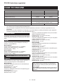
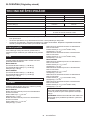
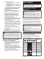
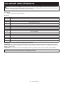
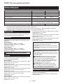
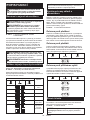
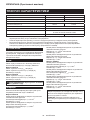
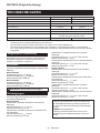
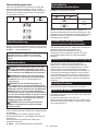
SPECIFICATIONS
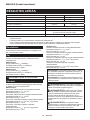
Model: DGA700 DGA900
Wheel diameter 180mm 230mm
Max. wheel thickness 7.2mm 6.5mm
Spindle thread M14 or M16 or 5/8″ (country specic)
Rated speed (n) 7,800min-1 6,000min-1
Overall length 499mm
Rated voltage D.C.36 V
Battery cartridge BL1815N, BL1820, BL1820B, BL1830, BL1830B, BL1840,
BL1840B, BL1850, BL1850B, BL1860B
Net weight 5.0 - 6.0 kg 5.2 - 8.0 kg
•
Due to our continuing program of research and development, the specications herein are subject to change without notice.
• Specications and battery cartridge may differ from country to country.
• The weight may differ depending on the attachment(s), including the battery cartridge. The lightest and heavi-
est combination, according to EPTA-Procedure 01/2014, are shown in the table.
Intended use
The tool is intended for grinding, sanding and cutting of
metal and stone materials without the use of water.
Noise
The typical A-weighted noise level determined accord-
ing to EN60745:
Model DGA700
Sound pressure level (LpA) : 88 dB(A)
Sound power level (LWA) : 99 dB (A)
Uncertainty (K) : 3 dB(A)
Model DGA900
Sound pressure level (LpA) : 88 dB(A)
Sound power level (LWA) : 99 dB (A)
Uncertainty (K) : 3 dB(A)
WARNING: Wear ear protection.
Vibration
The vibration total value (tri-axial vector sum) deter-
mined according to EN60745:
Model DGA700
Work mode: surface grinding with normal side grip
Vibration emission (ah, AG) : 7.5 m/s2
Uncertainty (K) : 1.5 m/s2
Work mode: surface grinding with anti vibration side grip
Vibration emission (ah, AG) : 7.5 m/s2
Uncertainty (K) : 1.5 m/s2
Work mode: disc sanding with normal side grip
Vibration emission (ah, DS) : 2.5 m/s2 or less
Uncertainty (K) : 1.5 m/s2
Work mode: disc sanding with anti vibration side grip
Vibration emission (ah, DS) : 2.5 m/s2 or less
Uncertainty (K) : 1.5 m/s2
Model DGA900
Work mode: surface grinding with normal side grip
Vibration emission (ah, AG) : 7.0 m/s2
Uncertainty (K) : 1.5 m/s2
Work mode: surface grinding with anti vibration side grip
Vibration emission (ah, AG) : 7.5 m/s2
Uncertainty (K) : 1.5 m/s2
Work mode: disc sanding with normal side grip
Vibration emission (ah, DS) : 2.5 m/s2 or less
Uncertainty (K) : 1.5 m/s2
Work mode: disc sanding with anti vibration side grip
Vibration emission (ah, DS) : 2.5 m/s2 or less
Uncertainty (K) : 1.5 m/s2
NOTE: The declared vibration emission value has
been measured in accordance with the standard test
method and may be used for comparing one tool with
another.
NOTE: The declared vibration emission value
may also be used in a preliminary assessment of
exposure.
WARNING: The vibration emission during actual
use of the power tool can differ from the declared
emission value depending on the ways in which the
tool is used.
WARNING: Be sure to identify safety measures
to protect the operator that are based on an estima-
tion of exposure in the actual conditions of use (taking
account of all parts of the operating cycle such as
the times when the tool is switched off and when it is
running idle in addition to the trigger time).
WARNING: The declared vibration emission
value is used for main applications of the power tool.
However if the power tool is used for other applica-
tions, the vibration emission value may be different.
EC Declaration of Conformity
For European countries only
The EC declaration of conformity is included as Annex A
to this instruction manual.

7ENGLISH
SAFETY WARNINGS
General power tool safety warnings
WARNING: Read all safety warnings, instruc-
tions, illustrations and specications provided
with this power tool. Failure to follow all instructions
listed below may result in electric shock, re and/or
serious injury.
Save all warnings and instruc-
tions for future reference.
The term "power tool" in the warnings refers to your
mains-operated (corded) power tool or battery-operated
(cordless) power tool.
Cordless grinder safety warnings
Safety Warnings Common for Grinding, Sanding,
Wire Brushing, or Abrasive Cutting-Off Operations:
1.
This power tool is intended to function as a
grinder, sander, wire brush or cut-off tool. Read
all safety warnings, instructions, illustrations
and specications provided with this power tool.
Failure to follow all instructions listed below may
result in electric shock, re and/or serious injury.
2.
Operations such as polishing are not recom-
mended to be performed with this power tool.
Operations for which the power tool was not designed
may create a hazard and cause personal injury.
3. Do not use accessories which are not speci-
cally designed and recommended by the tool
manufacturer. Just because the accessory can
be attached to your power tool, it does not assure
safe operation.
4. The rated speed of the accessory must be at
least equal to the maximum speed marked on
the power tool. Accessories running faster than
their rated speed can break and y apart.
5. The outside diameter and the thickness of your
accessory must be within the capacity rating
of your power tool. Incorrectly sized accessories
cannot be adequately guarded or controlled.
6.
Threaded mounting of accessories must match
the grinder spindle thread. For accessories
mounted by anges, the arbour hole of the
accessory must t the locating diameter of the
ange. Accessories that do not match the mounting
hardware of the power tool will run out of balance,
vibrate excessively and may cause loss of control.
7. Do not use a damaged accessory. Before each
use inspect the accessory such as abrasive
wheels for chips and cracks, backing pad for
cracks, tear or excess wear, wire brush for
loose or cracked wires. If power tool or acces-
sory is dropped, inspect for damage or install
an undamaged accessory. After inspecting and
installing an accessory, position yourself and
bystanders away from the plane of the rotating
accessory and run the power tool at maximum
no-load speed for one minute. Damaged acces-
sories will normally break apart during this test
time.
8. Wear personal protective equipment.
Depending on application, use face shield,
safety goggles or safety glasses. As appro-
priate, wear dust mask, hearing protectors,
gloves and workshop apron capable of stop-
ping small abrasive or workpiece fragments.
The eye protection must be capable of stopping
ying debris generated by various operations.
The dust mask or respirator must be capable of
ltrating particles generated by your operation.
Prolonged exposure to high intensity noise may
cause hearing loss.
9. Keep bystanders a safe distance away from
work area. Anyone entering the work area
must wear personal protective equipment.
Fragments of workpiece or of a broken accessory
may y away and cause injury beyond immediate
area of operation.
10. Hold the power tool by insulated gripping
surfaces only, when performing an operation
where the cutting tool may contact hidden
wiring. Contact with a "live" wire will also make
exposed metal parts of the power tool "live" and
could give the operator an electric shock.
11. Never lay the power tool down until the acces-
sory has come to a complete stop. The spinning
accessory may grab the surface and pull the
power tool out of your control.
12. Do not run the power tool while carrying it at
your side. Accidental contact with the spinning
accessory could snag your clothing, pulling the
accessory into your body.
13. Regularly clean the power tool’s air vents. The
motor’s fan will draw the dust inside the housing
and excessive accumulation of powdered metal
may cause electrical hazards.
14. Do not operate the power tool near ammable
materials. Sparks could ignite these materials.
15. Do not use accessories that require liquid
coolants. Using water or other liquid coolants
may result in electrocution or shock.
Kickback and Related Warnings
Kickback is a sudden reaction to a pinched or snagged
rotating wheel, backing pad, brush or any other acces-
sory. Pinching or snagging causes rapid stalling of the
rotating accessory which in turn causes the uncon-
trolled power tool to be forced in the direction opposite
of the accessory’s rotation at the point of the binding.
For example, if an abrasive wheel is snagged or
pinched by the workpiece, the edge of the wheel that is
entering into the pinch point can dig into the surface of
the material causing the wheel to climb out or kick out.
The wheel may either jump toward or away from the
operator, depending on direction of the wheel’s move-
ment at the point of pinching. Abrasive wheels may also
break under these conditions.
Kickback is the result of power tool misuse and/or
incorrect operating procedures or conditions and can be
avoided by taking proper precautions as given below.
1. Maintain a rm grip on the power tool and
position your body and arm to allow you to
resist kickback forces. Always use auxiliary
handle, if provided, for maximum control over
kickback or torque reaction during start-up.
The operator can control torque reactions or kick-
back forces, if proper precautions are taken.

8ENGLISH
2. Never place your hand near the rotating acces-
sory. Accessory may kickback over your hand.
3. Do not position your body in the area where
power tool will move if kickback occurs.
Kickback will propel the tool in direction opposite
to the wheel’s movement at the point of snagging.
4. Use special care when working corners, sharp
edges etc. Avoid bouncing and snagging the
accessory. Corners, sharp edges or bouncing
have a tendency to snag the rotating accessory
and cause loss of control or kickback.
5. Do not attach a saw chain woodcarving blade
or toothed saw blade. Such blades create fre-
quent kickback and loss of control.
Safety Warnings Specic for Grinding and Abrasive
Cutting-Off Operations:
1. Use only wheel types that are recommended
for your power tool and the specic guard
designed for the selected wheel. Wheels for
which the power tool was not designed cannot be
adequately guarded and are unsafe.
2. The grinding surface of centre depressed
wheels must be mounted below the plane of
the guard lip. An improperly mounted wheel that
projects through the plane of the guard lip cannot
be adequately protected.
3. The guard must be securely attached to the
power tool and positioned for maximum safety,
so the least amount of wheel is exposed
towards the operator. The guard helps to protect
the operator from broken wheel fragments, acci-
dental contact with wheel and sparks that could
ignite clothing.
4. Wheels must be used only for recommended
applications. For example: do not grind with
the side of cut-off wheel. Abrasive cut-off wheels
are intended for peripheral grinding, side forces
applied to these wheels may cause them to
shatter.
5. Always use undamaged wheel anges that are
of correct size and shape for your selected
wheel. Proper wheel anges support the wheel
thus reducing the possibility of wheel breakage.
Flanges for cut-off wheels may be different from
grinding wheel anges.
6. Do not use worn down wheels from larger
power tools. Wheel intended for larger power tool
is not suitable for the higher speed of a smaller
tool and may burst.
Additional Safety Warnings Specic for Abrasive
Cutting-Off Operations:
1. Do not “jam“ the cut-off wheel or apply exces-
sive pressure. Do not attempt to make an
excessive depth of cut. Overstressing the wheel
increases the loading and susceptibility to twisting
or binding of the wheel in the cut and the possibil-
ity of kickback or wheel breakage.
2. Do not position your body in line with and
behind the rotating wheel. When the wheel, at
the point of operation, is moving away from your
body, the possible kickback may propel the spin-
ning wheel and the power tool directly at you.
3. When wheel is binding or when interrupting
a cut for any reason, switch off the power
tool and hold the power tool motionless until
the wheel comes to a complete stop. Never
attempt to remove the cut-off wheel from the
cut while the wheel is in motion otherwise
kickback may occur. Investigate and take correc-
tive action to eliminate the cause of wheel binding.
4. Do not restart the cutting operation in the
workpiece. Let the wheel reach full speed and
carefully re-enter the cut. The wheel may bind,
walk up or kickback if the power tool is restarted in
the workpiece.
5. Support panels or any oversized workpiece to
minimize the risk of wheel pinching and kick-
back. Large workpieces tend to sag under their
own weight. Supports must be placed under the
workpiece near the line of cut and near the edge
of the workpiece on both sides of the wheel.
6. Use extra caution when making a “pocket cut”
into existing walls or other blind areas. The
protruding wheel may cut gas or water pipes, elec-
trical wiring or objects that can cause kickback.
Safety Warnings Specic for Sanding Operations:
1. Do not use excessively oversized sanding
disc paper. Follow manufacturers recommen-
dations, when selecting sanding paper. Larger
sanding paper extending beyond the sanding
pad presents a laceration hazard and may cause
snagging, tearing of the disc or kickback.
Safety Warnings Specic for Wire Brushing
Operations:
1. Be aware that wire bristles are thrown by the
brush even during ordinary operation. Do not
overstress the wires by applying excessive
load to the brush. The wire bristles can easily
penetrate light clothing and/or skin.
2. If the use of a guard is recommended for wire
brushing, do not allow any interference of the
wire wheel or brush with the guard. Wire wheel
or brush may expand in diameter due to work load
and centrifugal forces.
Additional Safety Warnings:
1. When using depressed centre grinding wheels,
be sure to use only berglass-reinforced
wheels.
2. NEVER USE Stone Cup type wheels with this
grinder. This grinder is not designed for these
types of wheels and the use of such a product
may result in serious personal injury.
3. Be careful not to damage the spindle, the
ange (especially the installing surface) or the
lock nut. Damage to these parts could result in
wheel breakage.
4. Make sure the wheel is not contacting the
workpiece before the switch is turned on.
5. Before using the tool on an actual workpiece,
let it run for a while. Watch for vibration or
wobbling that could indicate poor installation
or a poorly balanced wheel.
6. Use the specied surface of the wheel to per-
form the grinding.
7. Do not leave the tool running. Operate the tool
only when hand-held.

9ENGLISH
8. Do not touch the workpiece immediately after
operation; it may be extremely hot and could
burn your skin.
9. Observe the instructions of the manufacturer
for correct mounting and use of wheels.
Handle and store wheels with care.
10. Do not use separate reducing bushings or
adaptors to adapt large hole abrasive wheels.
11. Use only anges specied for this tool.
12. For tools intended to be tted with threaded
hole wheel, ensure that the thread in the wheel
is long enough to accept the spindle length.
13. Check that the workpiece is properly
supported.
14. Pay attention that the wheel continues to
rotate after the tool is switched off.
15. If working place is extremely hot and humid,
or badly polluted by conductive dust, use a
short-circuit breaker (30 mA) to assure opera-
tor safety.
16. Do not use the tool on any materials contain-
ing asbestos.
17. When use cut-off wheel, always work with
the dust collecting wheel guard required by
domestic regulation.
18. Cutting discs must not be subjected to any
lateral pressure.
19. Do not use cloth work gloves during operation.
Fibers from cloth gloves may enter the tool, which
causes tool breakage.
SAVE THESE INSTRUCTIONS.
WARNING: DO NOT let comfort or familiarity
with product (gained from repeated use) replace
strict adherence to safety rules for the subject
product. MISUSE or failure to follow the safety
rules stated in this instruction manual may cause
serious personal injury.
Important safety instructions for
battery cartridge
1. Before using battery cartridge, read all instruc-
tions and cautionary markings on (1) battery
charger, (2) battery, and (3) product using
battery.
2. Do not disassemble battery cartridge.
3. If operating time has become excessively
shorter, stop operating immediately. It may
result in a risk of overheating, possible burns
and even an explosion.
4. If electrolyte gets into your eyes, rinse them
out with clear water and seek medical atten-
tion right away. It may result in loss of your
eyesight.
5. Do not short the battery cartridge:
(1) Do not touch the terminals with any con-
ductive material.
(2) Avoid storing battery cartridge in a con-
tainer with other metal objects such as
nails, coins, etc.
(3) Do not expose battery cartridge to water
or rain.
A battery short can cause a large current
ow, overheating, possible burns and even a
breakdown.
6. Do not store the tool and battery cartridge in
locations where the temperature may reach or
exceed 50 °C (122 °F).
7. Do not incinerate the battery cartridge even if
it is severely damaged or is completely worn
out. The battery cartridge can explode in a re.
8. Be careful not to drop or strike battery.
9. Do not use a damaged battery.
10. The contained lithium-ion batteries are subject
to the Dangerous Goods Legislation require-
ments.
For commercial transports e.g. by third parties,
forwarding agents, special requirement on pack-
aging and labeling must be observed.
For preparation of the item being shipped, consult-
ing an expert for hazardous material is required.
Please also observe possibly more detailed
national regulations.
Tape or mask off open contacts and pack up the
battery in such a manner that it cannot move
around in the packaging.
11. Follow your local regulations relating to dis-
posal of battery.
SAVE THESE INSTRUCTIONS.
CAUTION: Only use genuine Makita batteries.
Use of non-genuine Makita batteries, or batteries that
have been altered, may result in the battery bursting
causing res, personal injury and damage. It will
also void the Makita warranty for the Makita tool and
charger.
Tips for maintaining maximum
battery life
1. Charge the battery cartridge before completely
discharged. Always stop tool operation and
charge the battery cartridge when you notice
less tool power.
2. Never recharge a fully charged battery car-
tridge. Overcharging shortens the battery
service life.
3. Charge the battery cartridge with room tem-
perature at 10 °C - 40 °C (50 °F - 104 °F). Let
a hot battery cartridge cool down before
charging it.
4. Charge the battery cartridge if you do not use
it for a long period (more than six months).

10 ENGLISH
FUNCTIONAL
DESCRIPTION
CAUTION: Always be sure that the tool is
switched off and the battery cartridge is removed
before adjusting or checking function on the tool.
Installing or removing battery cartridge
CAUTION: Always switch off the tool before
installing or removing of the battery cartridge.
CAUTION:
Hold the tool and the battery cartridge
rmly when installing or removing battery cartridge.
Failure to hold the tool and the battery cartridge rmly may
cause them to slip off your hands and result in damage to
the tool and battery cartridge and a personal injury.
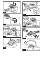
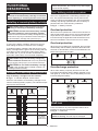
► Fig.1: 1. Red indicator 2. Button 3. Battery cartridge
To remove the battery cartridge, slide it from the tool
while sliding the button on the front of the cartridge.
To install the battery cartridge, align the tongue on the
battery cartridge with the groove in the housing and slip
it into place. Insert it all the way until it locks in place
with a little click. If you can see the red indicator on the
upper side of the button, it is not locked completely.
CAUTION:
Always install the battery cartridge fully
until the red indicator cannot be seen. If not, it may accidentally
fall out of the tool, causing injury to you or someone around you.
CAUTION: Do not install the battery cartridge
forcibly. If the cartridge does not slide in easily, it is
not being inserted correctly.
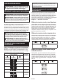
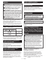
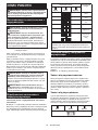
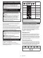
Indicating the remaining battery capacity
Only for battery cartridges with the indicator
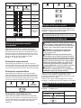
► Fig.2: 1. Indicator lamps 2. Check button
Press the check button on the battery cartridge to indi-
cate the remaining battery capacity. The indicator lamps
light up for a few seconds.
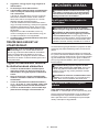
Indicator lamps Remaining
capacity
Lighted Off Blinking
75% to 100%
50% to 75%
25% to 50%
0% to 25%
Charge the
battery.
The battery
may have
malfunctioned.
NOTE: Depending on the conditions of use and the
ambient temperature, the indication may differ slightly
from the actual capacity.
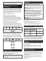
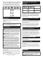
Tool / battery protection system
The tool is equipped with a tool/battery protection sys-
tem. This system automatically cuts off power to the
motor to extend tool and battery life. The tool will auto-
matically stop during operation if the tool or battery is
placed under one of the following conditions:
► Fig.3: 1. Battery indicator
Overload protection
When the tool is operated in a manner that causes it to
draw an abnormally high current, the tool automatically
stops without any indication. In this situation, turn the
tool off and stop the application that caused the tool to
become overloaded. Then turn the tool on to restart.
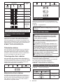
Overheat protection
When the tool or batteries is overheated, the tool stops
automatically and the battery indicators blink about 60
seconds. In this situation, let the tool and batteries cool
before turning the tool on again.
On Off Blinking
Overdischarge protection
When either battery's capacity becomes too low, the
tool stops automatically and the battery indicator on its
side lights up. In this case, remove the battery from the
tool and charge the battery.
On Off Blinking
Shaft lock
Press the shaft lock to prevent spindle rotation when
installing or removing accessories.
► Fig.4: 1. Shaft lock
NOTICE: Never actuate the shaft lock when the
spindle is moving. The tool may be damaged.

11 ENGLISH
Switch action
CAUTION: Before installing the battery car-
tridge into the tool, always check to see that the
switch lever actuates properly and returns to the
"OFF" position when released.
CAUTION: Do not pull the switch lever hard
without pulling the lock-off lever. This can cause
switch breakage.
CAUTION: For your safety, this tool is
equipped with lock-off lever which prevents the
tool from unintended starting. NEVER use the tool
if it runs when you simply pull the switch trigger
without pulling the lock-off lever. Return the tool
to our authorized service center for proper repairs
BEFORE further usage.
CAUTION: NEVER tape down or defeat pur-
pose and function of lock-off lever.
To prevent the switch lever from being accidentally
pulled, a lock-off lever is provided.
To start the tool, fold the lock-off lever and then pull the
switch lever.
To stop the tool, release the switch lever.
► Fig.5: 1. Lock-off lever 2. Switch lever
Automatic speed change function
► Fig.6: 1. Mode indicator
Mode indicator status Operation mode
On Off
High speed mode
High torque mode
This tool has "high speed mode" and "high torque
mode". It automatically changes operation mode
depending on the work load. When mode indicator
lights up during operation, the tool is in high torque
mode.
Accidental re-start preventive
function
Even if installing the battery cartridge while pulling the
switch lever, the tool does not start.
To start the tool, rst release the switch lever. Then pull
the lock-off lever, and pull the switch lever.
Electronic torque control function
The tool electronically detects situations where the
wheel or accessory may be at risk to be bound. In the
situation, the tool is automatically shut off to prevent
further rotation of the spindle (it does not prevent
kickback).
To restart the tool, switch off the tool rst, remove the
cause of sudden drop in the rotation speed, and then
turn the tool on.
Soft start feature
Soft start feature reduces starting reaction.
Electric brake
Electric brake is activated after the tool is switched off.
The brake does not work when the power supply is shut
down, such as the battery is removed accidentally, with
the switch still on.
ASSEMBLY
CAUTION: Always be sure that the tool is
switched off and the battery cartridge is removed
before adjusting or checking function on the tool.
Installing side grip (handle)
CAUTION: Always be sure that the side grip is
installed securely before operation.
Screw the side grip securely on the position of the tool
as shown in the gure.
► Fig.7
Installing or removing wheel guard
(For depressed center wheel, ap
disc, ex wheel, wire wheel brush
/ abrasive cut-off wheel, diamond
wheel)
WARNING: When using a depressed center
wheel, ap disc, ex wheel or wire wheel brush,
the wheel guard must be tted on the tool so that
the closed side of the guard always points toward
the operator.
WARNING: When using an abrasive cut-off
/ diamond wheel, be sure to use only the special
wheel guard designed for use with cut-off wheels.
(In some European countries, when using a diamond
wheel, the ordinary guard can be used. Follow the
regulations in your country.)
For tool with locking screw type
wheel guard
Mount the wheel guard with the protrusions on the
wheel guard band aligned with the notches on the bear-
ing box. Then rotate the wheel guard to such an angle
that it can protect the operator according to work. Be
sure to tighten the screw securely.
To remove wheel guard, follow the installation proce-
dure in reverse.
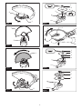
► Fig.8: 1. Wheel guard 2. Bearing box 3. Screw

12 ENGLISH
For tool with clamp lever type wheel
guard
Loosen the nut, and then pull the lever in the direction
of the arrow.
► Fig.9: 1. Nut 2. Lever
Mount the wheel guard with the protrusions on the
wheel guard band aligned with the notches on the bear-
ing box. Then rotate the wheel guard to such an angle
that it can protect the operator according to work.
► Fig.10: 1. Wheel guard 2. Bearing box
► Fig.11: 1. Wheel guard
Close the lever in direction of the arrow. Then tighten
the wheel guard with fastening the nut. Be sure to
tighten the nut securely. The setting angle of the wheel
guard can be adjusted by opening the lever.
► Fig.12: 1. Lever 2. Nut
To remove wheel guard, follow the installation proce-
dure in reverse.
Installing or removing depressed
center wheel or ap disc
Optional accessory
WARNING: When using a depressed center
wheel or ap disc, the wheel guard must be tted
on the tool so that the closed side of the guard
always points toward the operator.
CAUTION: Make sure that the mounting part
of the inner ange ts into the inner diameter of
the depressed center wheel / ap disc perfectly.
Mounting the inner ange on the wrong side may
result in the dangerous vibration.
Mount the inner ange onto the spindle.
Make sure to t the dented part of the inner ange onto
the straight part at the bottom of the spindle.
Fit the wheel/ disc on the inner ange and screw the
lock nut with its protrusion facing downward (facing
towards the wheel).
► Fig.13: 1. Lock nut 2. Depressed center wheel
3. Inner ange 4. Mounting part
To tighten the lock nut, press the shaft lock rmly so
that the spindle cannot revolve, then use the lock nut
wrench and securely tighten clockwise.
► Fig.14: 1. Lock nut wrench 2. Shaft lock
To remove the wheel, follow the installation procedure
in reverse.
Installing or removing ex wheel
Optional accessory
WARNING: Always use supplied guard when
ex wheel is on tool. Wheel can shatter during use
and guard helps to reduce chances of personal injury.
► Fig.15: 1. Lock nut 2. Flex wheel 3. Back up pad
4. Inner ange
Follow instructions for depressed center wheel but also
use back up pad over wheel. See order of assembly on
accessories page in this manual.
Installing or removing abrasive disc
Optional accessory
► Fig.16: 1. Sanding lock nut 2. Abrasive disc
3. Rubber pad
1. Mount the rubber pad onto the spindle.
2. Fit the disc on the rubber pad and screw the sand-
ing lock nut onto the spindle.
3.
Hold the spindle with the shaft lock, and securely tighten
the sanding lock nut clockwise with the lock nut wrench.
To remove the disc, follow the installation procedure in
reverse.
NOTE: Use sander accessories specied in this man-
ual. These must be purchased separately.
OPERATION
WARNING: It should never be necessary to
force the tool. The weight of the tool applies ade-
quate pressure. Forcing and excessive pressure
could cause dangerous wheel breakage.
WARNING: ALWAYS replace wheel if tool is
dropped while grinding.
WARNING: NEVER bang or hit grinding disc
or wheel onto work.
WARNING:
Avoid bouncing and snagging the
wheel, especially when working corners, sharp
edges etc. This can cause loss of control and kickback.
WARNING: NEVER use tool with wood cutting
blades and other saw blades. Such blades when
used on a grinder frequently kick and cause loss of
control leading to personal injury.
CAUTION: Never switch on the tool when it
is in contact with the workpiece, it may cause an
injury to operator.
CAUTION: Always wear safety goggles or a
face shield during operation.
CAUTION: After operation, always switch off
the tool and wait until the wheel has come to a
complete stop before putting the tool down.
CAUTION: ALWAYS hold the tool rmly with
one hand on housing and the other on the side
grip (handle).
Grinding and sanding operation
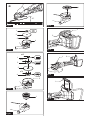
► Fig.17
Turn the tool on and then apply the wheel or disc to the
workpiece.
In general, keep the edge of the wheel or disc at an
angle of about 15° to the workpiece surface.
During the break-in period with a new wheel, do not
work the grinder in forward direction or it may cut into
the workpiece. Once the edge of the wheel has been
rounded off by use, the wheel may be worked in both
forward and backward direction.

13 ENGLISH
Operation with abrasive cut-off /
diamond wheel
Optional accessory
WARNING: When using an abrasive cut-off
/ diamond wheel, be sure to use only the special
wheel guard designed for use with cut-off wheels.
(In some European countries, when using a diamond
wheel, the ordinary guard can be used. Follow the
regulations in your country.)
WARNING: NEVER use cut-off wheel for side
grinding.
WARNING: Do not "jam" the wheel or apply
excessive pressure. Do not attempt to make an
excessive depth of cut. Overstressing the wheel
increases the loading and susceptibility to twisting
or binding of the wheel in the cut and the possibility
of kickback, wheel breakage and overheating of the
motor may occur.
WARNING: Do not start the cutting operation
in the workpiece. Let the wheel reach full speed
and carefully enter into the cut moving the tool
forward over the workpiece surface. The wheel
may bind, walk up or kickback if the power tool is
started in the workpiece.
WARNING: During cutting operations, never
change the angle of the wheel. Placing side pres-
sure on the cut-off wheel (as in grinding) will cause
the wheel to crack and break, causing serious per-
sonal injury.
WARNING: A diamond wheel shall be oper-
ated perpendicular to the material being cut.
Mount the inner ange onto the spindle.
Fit the wheel / disc on the inner ange and screw the
lock nut onto the spindle.
► Fig.18: 1. Lock nut 2. Abrasive cut-off wheel / dia-
mond wheel 3. Inner ange 4. Wheel guard
for abrasive cut-off wheel / diamond wheel
For Australia and New Zealand
► Fig.19: 1. Lock nut 2. Outer ange 78 3. Abrasive
cut-off wheel / diamond wheel 4. Inner
ange 78 5. Wheel guard for abrasive cut-
off wheel / diamond wheel
Operation with wire cup brush
Optional accessory
CAUTION: Check operation of brush by run-
ning tool with no load, insuring that no one is in
front of or in line with brush.
CAUTION: Do not use brush that is damaged,
or which is out of balance. Use of damaged brush
could increase potential for injury from contact with
broken brush wires.
► Fig.20: 1. Wire cup brush
Remove the battery cartridge and place the tool upside
down allowing easy access to spindle.
Remove any accessories on spindle. Thread wire cup
brush onto spindle and tighten with supplied wrench.
NOTICE: Avoid applying too much pressure
which causes over bending of wires when using
brush. It may lead to premature breakage.
Operation with wire wheel brush
Optional accessory
CAUTION: Check operation of wire wheel
brush by running tool with no load, insuring that
no one is in front of or in line with the wire wheel
brush.
CAUTION: Do not use wire wheel brush that
is damaged, or which is out of balance. Use of
damaged wire wheel brush could increase potential
for injury from contact with broken wires.
CAUTION: ALWAYS use guard with wire
wheel brushes, assuring diameter of wheel ts
inside guard. Wheel can shatter during use and
guard helps to reduce chances of personal injury.
► Fig.21: 1. Wire wheel brush
Remove the battery cartridge and place the tool upside
down allowing easy access to spindle.
Remove any accessories on spindle. Thread wire wheel
brush onto spindle and tighten with the wrenches.
NOTICE: Avoid applying too much pressure
which causes over bending of wires when
using wire wheel brush. It may lead to premature
breakage.
MAINTENANCE
CAUTION: Always be sure that the tool is
switched off and the battery cartridge is removed
before attempting to perform inspection or
maintenance.
NOTICE: Never use gasoline, benzine, thinner,
alcohol or the like. Discoloration, deformation or
cracks may result.
Battery guard
WARNING: Do not remove the battery
guard. Do not use the tool with the battery guard
removed or damaged. Direct impact to the battery
cartridge may cause battery malfunction and result
in injury and/or re. If the battery guard is deformed
or damaged, contact your authorized service center
for repairs.
► Fig.22: 1. Battery guard 2. Battery guard holder

14 ENGLISH
Air vent cleaning
The tool and its air vents have to be kept clean.
Regularly clean the tool's air vents or whenever the
vents start to become obstructed.
► Fig.23: 1. Exhaust vent 2. Inhalation vent
Remove the dust cover from inhalation vent and clean it
for smooth air circulation.
► Fig.24: 1. Dust cover
NOTICE: Clean out the dust cover when it is
clogged with dust or foreign matters. Continuing
operation with a clogged dust cover may damage the
tool.
To maintain product SAFETY and RELIABILITY,
repairs, any other maintenance or adjustment should
be performed by Makita Authorized or Factory Service
Centers, always using Makita replacement parts.
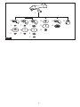
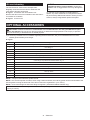
OPTIONAL ACCESSORIES
CAUTION: These accessories or attachments are recommended for use with your Makita tool spec-
ied in this manual. The use of any other accessories or attachments might present a risk of injury to persons.
Only use accessory or attachment for its stated purpose.
If you need any assistance for more details regarding these accessories, ask your local Makita Service Center.
• Makita genuine battery and charger
► Fig.25
1Side grip
2Wheel guard for depressed center wheel / ap disc / wire wheel brush
3Inner ange *1
4Depressed center wheel / Flap disc
5Lock nut / Ezynut *1
6Wheel guard for abrasive cut off wheel / diamond wheel *2
7Inner ange 78 (Australia and New Zealand only) *3
8Abrasive cut-off wheel / Diamond wheel
9Outer ange 78 (Australia and New Zealand only) *3
10 Rubber pad
11 Abrasive disc
12 Sanding lock nut
13 Wire wheel brush
14 Wire cup brush
-Lock nut wrench
-Dust cover attachment
NOTE: *1 Only for tools with M14 spindle thread.
NOTE: *2 In some European countries, when using a diamond wheel, the ordinary guard can be used instead of the
special guard covering the both side of the wheel. Follow the regulations in your country.
NOTE: *3 Use Inner ange 78 and Outer ange 78 together. (Australia and New Zealand only)
NOTE: Some items in the list may be included in the tool package as standard accessories. They may differ from
country to country.

15 POLSKI
POLSKI (Instrukcja oryginalna)
DANE TECHNICZNE
Model: DGA700 DGA900
Średnica ściernicy 180mm 230mm
Maks. grubość ściernicy 7,2mm 6,5mm
Gwint wrzeciona M14 lub M16 lub 5/8″ (w zależności od kraju)
Prędkość znamionowa (n) 7 800min-1 6 000min-1
Długość całkowita 499mm
Napięcie znamionowe Napięcie stałe 36 V
Akumulator BL1815N, BL1820, BL1820B, BL1830, BL1830B, BL1840,
BL1840B, BL1850, BL1850B, BL1860B
Masa netto 5,0–6,0 kg 5,2–8,0 kg
• W związku ze stale prowadzonym przez naszą rmę programem badawczo-rozwojowym niniejsze dane mogą
ulec zmianom bez wcześniejszego powiadomienia.
• W innych krajach urządzenie może mieć odmienne parametry techniczne i może być wyposażone w inny
akumulator.
• Masa może być różna w zależności od osprzętu, w tym akumulatora. W tabeli przedstawiona jest najlżejsza i
najcięższa konguracja, zgodnie z procedurą EPTA 01/2014.
Przeznaczenie
Omawiane narzędzie jest przeznaczone do szlifowania i
cięcia materiałów metalowych i kamiennych bez użycia
wody.
Hałas
Typowy równoważny poziom dźwięku A określony w
oparciu o normę EN60745:
Model DGA700
Poziom ciśnienia akustycznego (LpA): 88 dB(A)
Poziom mocy akustycznej (LWA): 99 dB (A)
Niepewność (K): 3 dB(A)
Model DGA900
Poziom ciśnienia akustycznego (LpA): 88 dB(A)
Poziom mocy akustycznej (LWA): 99 dB (A)
Niepewność (K): 3 dB(A)
OSTRZEŻENIE: Nosić ochronniki słuchu.
Drgania
Całkowita wartość poziomu drgań (suma wektorów w 3
osiach) określona zgodnie z normą EN60745:
Model DGA700
Tryb pracy: szlifowanie powierzchni ze standardowym
uchwytem bocznym
Emisja drgań (ah, AG): 7,5 m/s2
Niepewność (K): 1,5 m/s2
Tryb pracy: szlifowanie powierzchni z antywibracyjnym
uchwytem bocznym
Emisja drgań (ah, AG): 7,5m/s2
Niepewność (K): 1,5 m/s2
Tryb pracy: szlifowanie krążkami ściernymi ze standar-
dowym uchwytem bocznym
Emisja drgań (ah, DS): 2,5 m/s2 lub mniej
Niepewność (K): 1,5 m/s2
Tryb pracy: szlifowanie krążkami ściernymi z antywibra-
cyjnym uchwytem bocznym
Emisja drgań (ah, DS): 2,5 m/s2 lub mniej
Niepewność (K): 1,5 m/s2
Model DGA900
Tryb pracy: szlifowanie powierzchni ze standardowym
uchwytem bocznym
Emisja drgań (ah, AG): 7,0 m/s2
Niepewność (K): 1,5 m/s2
Tryb pracy: szlifowanie powierzchni z antywibracyjnym
uchwytem bocznym
Emisja drgań (ah, AG): 7,5m/s2
Niepewność (K): 1,5 m/s2
Tryb pracy: szlifowanie krążkami ściernymi ze standar-
dowym uchwytem bocznym
Emisja drgań (ah, DS): 2,5 m/s2 lub mniej
Niepewność (K): 1,5 m/s2
Tryb pracy: szlifowanie krążkami ściernymi z antywibra-
cyjnym uchwytem bocznym
Emisja drgań (ah, DS): 2,5 m/s2 lub mniej
Niepewność (K): 1,5 m/s2
WSKAZÓWKA: Deklarowana wartość wytwarzanych
drgań została zmierzona zgodnie ze standardową
metodą testową i można ją wykorzystać do porówny-
wania narzędzi.
WSKAZÓWKA: Deklarowaną wartość wytwarzanych
drgań można także wykorzystać we wstępnej ocenie
narażenia.

16 POLSKI
OSTRZEŻENIE:
Drgania wytwarzane podczas rzeczy-
wistego użytkowania elektronarzędzia mogą się różnić od warto-
ści deklarowanej, w zależności od sposobu jego użytkowania.
OSTRZEŻENIE:
W oparciu o szacowane nara-
żenie w rzeczywistych warunkach użytkowania należy
określić środki bezpieczeństwa w celu ochrony opera-
tora (uwzględniając wszystkie elementy cyklu działania,
tj. czas, kiedy narzędzie jest wyłączone i kiedy pracuje
na biegu jałowym, a także czas, kiedy jest włączone).
OSTRZEŻENIE:
Deklarowaną wartość emisji drgań
stosuje się do głównych zastosowań elektronarzędzia.
Jeśli jednak elektronarzędzie będzie wykorzystywane do
innych zastosowań, wartość emisji drgań może być inna.
Deklaracja zgodności WE
Dotyczy tylko krajów europejskich
Deklaracja zgodności WE jest dołączona jako załącznik
A do niniejszej instrukcji obsługi.
OSTRZEŻENIA
DOTYCZĄCE
BEZPIECZEŃSTWA
Ogólne zasady bezpiecznej
eksploatacji elektronarzędzi
OSTRZEŻENIE:
Należy zapoznać się z ostrze-
żeniami dotyczącymi bezpieczeństwa, instrukcjami,
ilustracjami i danymi technicznymi dołączonymi do
tego elektronarzędzia. Niezastosowanie się do poda-
nych poniżej instrukcji może prowadzić do porażenia
prądem, pożaru i/lub poważnych obrażeń ciała.
Wszystkie ostrzeżenia i instruk-
cje należy zachować do wykorzy-
stania w przyszłości.
Pojęcie „elektronarzędzie", występujące w wymienionych tu
ostrzeżeniach, odnosi się do elektronarzędzia zasilanego z
sieci elektrycznej (z przewodem zasilającym) lub do elektro-
narzędzia akumulatorowego (bez przewodu zasilającego).
Ostrzeżenia dotyczące bezpieczeństwa
dla akumulatorowej szlierki kątowej
Ostrzeżenia dotyczące bezpieczeństwa podczas
operacji szlifowania, czyszczenia powierzchni
szczotką drucianą lub cięcia przy użyciu ściernicy:
1.
Opisywane elektronarzędzie jest przeznaczone
do szlifowania, czyszczenia powierzchni
szczotką drucianą i cięcia. Należy zapoznać się
z ostrzeżeniami dotyczącymi bezpieczeństwa,
instrukcjami, ilustracjami i danymi technicz-
nymi dołączonymi do tego elektronarzędzia.
Niezastosowanie się do podanych poniżej instrukcji
może prowadzić do porażenia prądem elektrycz-
nym, pożaru i/lub poważnych obrażeń ciała.
2. Nie zaleca się używania niniejszego elektro-
narzędzia do wykonywania takich operacji jak
polerowanie. Operacje, do których elektronarzę-
dzie nie jest przeznaczone, mogą stwarzać zagro-
żenie i spowodować obrażenia ciała.
3. Nie używać osprzętu, który nie jest przezna-
czony ani zalecany specjalnie do tego narzę-
dzia przez jego producenta. Fakt, że osprzęt
można zamocować do posiadanego elektronarzę-
dzia, wcale nie gwarantuje bezpiecznej pracy.
4. Prędkość znamionowa osprzętu powinna być
przynajmniej równa maksymalnej prędkości
podanej na elektronarzędziu. Osprzęt pracujący
przy większej prędkości niż jego prędkość zna-
mionowa może pęknąć i rozpaść się na kawałki.
5.
Zewnętrzna średnica i grubość osprzętu musi
mieścić się w zakresie dopuszczalnym dla tego
elektronarzędzia. Nie można zapewnić prawidłowej
osłony i kontroli osprzętu o niewłaściwym rozmiarze.
6.
Osprzęt montowany na gwint musi pasować do
gwintu wrzeciona szlierki. W przypadku osprzętu
montowanego przy użyciu kołnierzy otwór
wewnętrzny osprzętu musi pasować do średnicy
kołnierza. Osprzęt, który nie jest dopasowany do
uchwytu mocującego w elektronarzędziu będzie
niewyważony podczas pracy, powodując nadmierne
drgania i ryzyko utraty kontroli nad narzędziem.
7.
Nie używać uszkodzonego osprzętu. Przed
każdorazowym użyciem osprzęt, np. ściernice,
należy skontrolować pod kątem ubytków lub
pęknięć, tarcze oporowe należy skontrolować
pod kątem pęknięć, uszkodzeń lub nadmier-
nego zużycia, a szczotki druciane pod kątem
luźnych lub popękanych drutów. W przypadku
upuszczenia elektronarzędzia lub osprzętu
należy sprawdzić, czy nie doszło do uszkodze-
nia, lub zamontować nieuszkodzony osprzęt.
Po sprawdzeniu bądź zamontowaniu osprzętu
należy stanąć w taki sposób i tak ustawić narzę-
dzie, aby nikt nie znajdował się w płaszczyźnie
obrotu osprzętu, po czym na jedną minutę
uruchomić elektronarzędzie z maksymalną
prędkością bez obciążenia. Uszkodzony osprzęt
zazwyczaj rozpadnie się podczas takiej próby.
8. Używać środków ochrony osobistej. W
zależności od wykonywanej operacji należy
używać osłony twarzy, gogli lub okularów
ochronnych. W miarę potrzeb zakładać maskę
przeciwpyłową, ochronniki słuchu, rękawice
i fartuch, który zatrzyma drobiny materiału
ściernego i obrabianego przedmiotu. Środki
ochrony oczu powinny zatrzymywać unoszące
się w powietrzu drobiny materiału, które powstają
podczas różnych operacji. Maska przeciwpyłowa
lub oddechowa powinna ltrować cząsteczki,
które powstają podczas pracy. Przebywanie przez
dłuższy czas w hałasie o dużym natężeniu może
spowodować utratę słuchu.
9. Trzymać osoby postronne w bezpiecznej odle-
głości od miejsca pracy. Każdy, kto wchodzi
do obszaru roboczego, musi używać środków
ochrony osobistej. Fragmenty materiału z obra-
bianego elementu lub pękniętego osprzętu mogą
zostać odrzucone na dużą odległość i spowo-
dować obrażenia poza bezpośrednim obszarem
roboczym.

17 POLSKI
10. Trzymać elektronarzędzie za izolowane
powierzchnie rękojeści podczas wykonywa-
nia prac, przy których narzędzie tnące może
dotknąć niewidocznej instalacji elektrycznej.
Zetknięcie z przewodem elektrycznym znajdują-
cym się pod napięciem spowoduje, że odsłonięte
elementy metalowe narzędzia również znajdą
się pod napięciem, grożąc porażeniem operatora
prądem elektrycznym.
11. Nie wolno odkładać elektronarzędzia, dopóki
zamontowany osprzęt całkowicie się nie
zatrzyma. Wirujący osprzęt może zahaczyć o
powierzchnię i wyrwać elektronarzędzie z ręki.
12. Uruchomionego elektronarzędzia nie wolno
przenosić z miejsca na miejsce. Przypadkowy
kontakt z wirującym osprzętem może spowodo-
wać zahaczenie ubrania i obrażenia ciała.
13. Otwory wentylacyjne elektronarzędzia należy
regularnie czyścić. Wentylator silnika wciąga
do wnętrza obudowy pył. Zbyt duże nagroma-
dzenie metalowych drobin stwarza zagrożenia
elektryczne.
14. Nie używać elektronarzędzia w pobliżu mate-
riałów łatwopalnych. Iskry mogą spowodować
zapłon takich materiałów.
15. Nie używać osprzętu, który wymaga stosowa-
nia ciekłego chłodziwa. Użycie wody lub innych
ciekłych chłodziw może spowodować porażenie
prądem elektrycznym, także śmiertelne.
Odrzut i związane z nim ostrzeżenia
Odrzut to gwałtowna reakcja narzędzia na zakleszcze-
nie lub zahaczenie obracającej się ściernicy, tarczy opo-
rowej, szczotki drucianej lub innego rodzaju osprzętu.
Zakleszczenie lub zahaczenie powoduje nagłe zatrzy-
manie obracającego się osprzętu, co z kolei prowadzi
do niekontrolowanego odrzutu elektronarzędzia do
kierunku obrotu osprzętu w miejscu zakleszczenia.
Przykładowo, jeśli ściernica zahaczy się lub zaklesz-
czy w obrabianym elemencie, jej krawędź w punkcie
zakleszczenia może wbić się powierzchnie materiału,
powodując wypychanie i odskoczenie narzędzia na
zewnątrz elementu. Ściernica może odskoczyć w stronę
operatora lub w kierunku przeciwnym, w zależności od
kierunku obrotów ściernicy w punkcie zakleszczenia.
W takich warunkach może również dojść do pęknięcia
ściernicy.
Odrzut jest wynikiem nieprawidłowego używania elek-
tronarzędzia i/lub niewłaściwych procedur lub warun-
ków jego obsługi. Można tego uniknąć, podejmując
odpowiednie środki ostrożności, które podano poniżej.
1. Przez cały czas należy mocno trzymać elektro-
narzędzie, ustawiając ciało i ramię w taki spo-
sób, aby przeciwdziałać siłom odrzutu. Zawsze
należy korzystać z rękojeści pomocniczej,
jeśli jest w zestawie, aby móc w pełni kontro-
lować odrzut lub przeciwdziałać momentowi
obrotowemu podczas rozruchu. Operator może
kontrolować reakcje na moment obrotowy lub siły
odrzutu w przypadku stosowania odpowiednich
środków ostrożności.
2. Nie wolno trzymać rąk w pobliżu obracającego
się osprzętu. Może bowiem nastąpić odrzut w
kierunku ręki.
3. Ciało operatora nie powinno znajdować się w
obszarze, do którego przemieści się elektro-
narzędzie w przypadku wystąpienia odrzutu.
Odrzut spowoduje wyrzucenie narzędzia w kie-
runku przeciwnym do kierunku obrotów ściernicy
w miejscu zakleszczenia.
4. Zachować szczególną ostrożność podczas
obróbki narożników, ostrych krawędzi itp. Nie
dopuszczać do odskakiwania i zahaczania się
osprzętu. Narożniki, ostre krawędzie lub odska-
kiwanie sprzyjają zahaczaniu obracającego się
osprzętu i mogą spowodować utratę kontroli lub
odrzut.
5. Nie wolno montować do elektronarzędzia tarcz
łańcuchowych do cięcia drewna ani zębatych
tarcz tnących. Tego typu tarcze często powodują
odrzut i utratę kontroli.
Ostrzeżenia dotyczące bezpieczeństwa podczas
operacji szlifowania i cięcia przy użyciu ściernicy:
1. Używać wyłącznie ściernic zalecanych do
posiadanego elektronarzędzia oraz specjal-
nych osłon przeznaczonych do wybranego
rodzaju ściernicy. Nie można zapewnić prawi-
dłowej osłony ściernic, do których elektronarzę-
dzie nie jest przeznaczone. Takie ściernice są
niebezpieczne.
2. Powierzchnia szlifowania ściernic z obniżo-
nym środkiem musi być zamontowana poniżej
płaszczyzny krawędzi osłony. Nieprawidłowo
zamontowana ściernica, która wystaje poza płasz-
czyznę krawędzi osłony, nie może być odpowied-
nio zabezpieczona.
3. Osłona powinna być dobrze przymocowana do
elektronarzędzia i ustawiona w sposób zapew-
niający maksimum bezpieczeństwa, tak aby w
stronę operatora był skierowany jak najmniej-
szy fragment odsłoniętej ściernicy. Osłona
chroni operatora przed wykruszonymi odłamkami
ściernicy, przypadkowym kontaktem ze ściernicą
oraz przed iskrami, które mogłyby zapalić odzież.
4. Ściernic należy używać tylko zgodnie z prze-
znaczeniem. Na przykład: nie wolno szlifo-
wać boczną powierzchnią ściernicy tnącej.
Ściernice tnące są przeznaczone do szlifowania
obwodowego. Siły boczne przyłożone do takich
ściernic mogą spowodować ich rozpadnięcie.
5. Zawsze używać nieuszkodzonych kołnierzy
mocujących o rozmiarze i kształcie właściwie
dobranym do wybranego rodzaju ściernicy.
Odpowiednie kołnierze mocujące podtrzymują
ściernicę, zmniejszając tym samym prawdopo-
dobieństwo jej pęknięcia. Kołnierze do ściernic
tnących mogą różnić się od kołnierzy do ściernic
szlierskich.
6. Nie używać zużytych ściernic przeznaczo-
nych do większych elektronarzędzi. Ściernica
przeznaczona do większych elektronarzędzi nie
nadaje się do użytku przy wyższych prędkościach
występujących w mniejszych narzędziach i może
się rozpaść.

18 POLSKI
Dodatkowe ostrzeżenia dotyczące bezpieczeństwa
podczas operacji cięcia przy użyciu ściernicy:
1.
Nie wolno doprowadzać do zakleszczenia ścier-
nicy tnącej ani stosować zbyt dużego nacisku.
Unikać cięć o zbyt dużej głębokości. Przeciążona
ściernica jest bardziej podatna na skręcenie lub
zakleszczenie w miejscu cięcia, co stwarza większe
prawdopodobieństwo odrzutu lub pęknięcia ściernicy.
2. Ciało operatora nie powinno znajdować się
w płaszczyźnie obrotu ściernicy ani za obra-
cającą się ściernicą. Gdy ściernica odsuwa się
podczas pracy od operatora, ewentualny odrzut
może wypchnąć wirującą ściernicę i elektronarzę-
dzie bezpośrednio w kierunku operatora.
3. W przypadku zakleszczenia się ściernicy lub
przerwania cięcia z jakiegokolwiek powodu,
należy wyłączyć elektronarzędzie i trzymać
je w bezruchu do momentu całkowitego
zatrzymania się ściernicy. Nie wolno wyciągać
ściernicy tnącej z przecinanego elementu, gdy
ściernica znajduje się w ruchu; w przeciwnym
razie może wystąpić odrzut. Zbadać przyczynę
zakleszczania się ściernicy i podjąć stosowne
działanie, aby wyeliminować ten problem.
4. Nie wolno wznawiać cięcia, gdy ściernica znaj-
duje się w przecinanym elemencie. Ściernicę
można ponownie włożyć do naciętej szczeliny
dopiero, gdy osiągnie pełną prędkość. Jeśli
elektronarzędzie zostanie ponownie uruchomione,
gdy ściernica znajduje się w przecinanym elemen-
cie, ściernica może się zakleszczyć, wędrować po
materiale lub może wystąpić odrzut.
5. Duże elementy lub płyty należy podpierać, aby
zminimalizować ryzyko zakleszczenia ścier-
nicy i wystąpienia odrzutu. Duże elementy mają
tendencję do uginania się pod własnym ciężarem.
Podpory muszą być umieszczone pod przeci-
nanym elementem w pobliżu linii cięcia oraz w
pobliżu krawędzi przecinanego elementu, po obu
stronach ściernicy.
6. Należy zachować szczególną ostrożność w
przypadku wykonywania „cięć wgłębnych”
w istniejących ścianach bądź innych zakry-
tych przestrzeniach. Wystająca ściernica może
przeciąć rury sieci gazowej lub wodociągowej,
przewody elektryczne lub przedmioty, które z kolei
mogą wywołać odrzut.
Specjalne ostrzeżenia dotyczące bezpieczeństwa
podczas operacji szlifowania:
1. Nie należy używać krążków papieru ściernego
o zbyt dużej średnicy. Przy doborze papieru
ściernego należy kierować się zaleceniami
producenta. Papier ścierny o zbyt dużych wymia-
rach, wystający poza obręb talerza szlierskiego,
grozi zranieniem i może powodować zaczepianie,
rozrywanie krążka lub odrzut.
Specjalne ostrzeżenia dotyczące bezpieczeństwa
podczas operacji czyszczenia powierzchni szczotką
drucianą:
1. Należy mieć świadomość, że nawet podczas
zwykłej pracy ze szczotki są wyrzucane
kawałki drutów. Nie wolno nadmiernie naprę-
żać drutów przez wywieranie zbyt dużego
nacisku na szczotkę. Druty ze szczotki mogą z
łatwością przebić lekkie ubranie i/lub skórę.
2. Jeśli podczas operacji czyszczenia
powierzchni szczotką drucianą wskazane jest
używanie osłony, należy uważać, aby szczotka
tarczowa ani druciana nie ocierały o osłonę.
Średnica szczotki tarczowej lub drucianej może
podczas pracy ulegać zwiększeniu pod wpływem
obciążenia roboczego i sił odśrodkowych.
Dodatkowe ostrzeżenia dotyczące bezpieczeństwa:
1. W przypadku używania ściernic z obniżonym
środkiem należy używać wyłącznie ściernic
wzmocnionych włóknem szklanym.
2. NIE WOLNO używać w tej szlierce ściernic
garnkowych. Niniejsza szlierka nie jest prze-
widziana do tego rodzaju ściernic i ich używanie
może spowodować poważne obrażenia ciała.
3. Uważać, aby nie uszkodzić wrzeciona, kołnie-
rza (zwłaszcza powierzchni odpowiedzialnych
za prawidłowy montaż) ani nakrętki zabezpie-
czającej. Uszkodzenie tych części może stać
się przyczyną pęknięcia ściernicy.
4. Przed włączeniem przełącznika należy się
upewnić, że ściernica nie dotyka obrabianego
elementu.
5. Przed rozpoczęciem obróbki danego elementu
pozwolić, aby urządzenie popracowało przez
chwilę bez obciążenia. Zwracać uwagę na
ewentualne drgania lub bicie osiowe, które
mogą wskazywać na nieprawidłowe zamoco-
wanie lub niedokładne wyważenie ściernicy.
6. Podczas szlifowania używać określonej
powierzchni ściernicy.
7. Nie pozostawiać włączonego narzędzia.
Narzędzie można uruchomić tylko, gdy jest
trzymane w rękach.
8. Nie dotykać elementu obrabianego od razu
po zakończeniu danej operacji; może być on
bardzo gorący i spowodować oparzenie skóry.
9. Przestrzegać instrukcji producenta w zakresie
mocowania i użytkowania ściernic. Ściernice
przechowywać i obchodzić się z nimi z
dbałością.
10. Nie wolno używać oddzielnych tulei reduk-
cyjnych ani elementów pośrednich w celu
zamocowania ściernic o dużym otworze
wewnętrznym.
11. Używać wyłącznie kołnierzy przeznaczonych
do tego narzędzia.
12. W przypadku narzędzi współpracujących ze
ściernicami z nagwintowanym otworem należy
sprawdzić, czy długość gwintu w ściernicy jest
wystarczająca, aby wkręcić wrzeciono na całej
długości.
13. Sprawdzić, czy obrabiany element jest dobrze
podparty.
14. Należy pamiętać, że po wyłączeniu narzędzia
ściernica nadal się obraca.
15. Jeśli w miejscu pracy panuje wyjątkowo
wysoka temperatura i wilgotność albo wystę-
puje silnie zanieczyszczone przewodzącym
pyłem, należy zastosować wyłącznik (30 mA),
aby zapewnić operatorowi bezpieczeństwo.
16. Nie wolno używać tego narzędzia do obróbki
materiałów zawierających azbest.

19 POLSKI
17. W przypadku używania ściernicy tnącej należy
zawsze stosować osłonę do odsysania pyłu
wymaganą przez obowiązujące przepisy
krajowe.
18. Na ściernice tnące nie wolno wywierać nacisku
poprzecznego.
19. Podczas pracy nie należy używać materia-
łowych rękawic roboczych. Włókna z rękawic
materiałowych mogą zostać pochwycone przez
narzędzie, co może spowodować uszkodzenie
narzędzia.
ZACHOWAĆ NINIEJSZĄ
INSTRUKCJĘ.
OSTRZEŻENIE: NIE WOLNO pozwolić,
aby wygoda lub rutyna (nabyta w wyniku wielo-
krotnego używania urządzenia) zastąpiły ścisłe
przestrzeganie zasad bezpieczeństwa obsługi.
NIEWŁAŚCIWE UŻYTKOWANIE narzędzia lub
niestosowanie się do zasad bezpieczeństwa
podanych w niniejszej instrukcji obsługi może
prowadzić do poważnych obrażeń ciała.
Ważne zasady bezpieczeństwa
dotyczące akumulatora
1. Przed użyciem akumulatora zapoznać się ze
wszystkimi instrukcjami i znakami ostrze-
gawczymi na (1) ładowarce, (2) akumulatorze
i (3) produkcie, w którym będzie używany
akumulator.
2. Akumulatora nie wolno rozbierać.
3. Jeśli czas działania uległ znacznemu skróce-
niu, należy natychmiast przerwać pracę. Może
bowiem dojść do przegrzania, ewentualnych
poparzeń, a nawet eksplozji.
4. W przypadku przedostania się elektrolitu do
oczu, przemyć je czystą wodą i niezwłocznie
uzyskać pomoc lekarską. Może on bowiem
spowodować utratę wzroku.
5. Nie doprowadzać do zwarcia akumulatora:
(1) Nie dotykać styków materiałami przewo-
dzącymi prąd.
(2) Unikać przechowywania akumulatora w
pojemniku z metalowymi przedmiotami,
takimi jak gwoździe, monety itp.
(3) Chronić akumulator przed deszczem lub
wodą.
Zwarcie prowadzi do przepływu prądu elek-
trycznego o dużym natężeniu i przegrzania
akumulatora, co w konsekwencji może grozić
poparzeniami a nawet awarią urządzenia.
6. Narzędzia i akumulatora nie wolno przecho-
wywać w miejscach, w których temperatura
osiąga bądź przekracza 50°C (122°F).
7. Akumulatorów nie wolno spalać, również tych
poważnie uszkodzonych lub całkowicie zuży-
tych. Akumulator może eksplodować w ogniu.
8. Chronić akumulator przed upadkiem i
uderzeniami.
9. Nie wolno używać uszkodzonego akumulatora.
10. Stanowiące wyposażenie akumulatory lito-
wo-jonowe podlegają przepisom dotyczącym
produktów niebezpiecznych.
Na potrzeby transportu komercyjnego, np. świad-
czonego przez rmy trzecie czy spedycyjne,
należy przestrzegać specjalnych wymagań w
zakresie pakowania i oznaczania etykietami.
Przygotowanie produktu do wysyłki wymaga
skonsultowania się ze specjalistą ds. materiałów
niebezpiecznych. Należy także przestrzegać
przepisów krajowych, które mogą być bardziej
szczegółowe.
Zakleić taśmą lub zaślepić otwarte styki akumula-
tora oraz zabezpieczyć go, aby nie mógł się prze-
suwać w opakowaniu.
11. Postępować zgodnie z przepisami lokalnymi
dotyczącymi usuwania akumulatorów.
ZACHOWAĆ NINIEJSZE
INSTRUKCJE.
PRZESTROGA: Używać wyłącznie oryginal-
nych akumulatorów rmy Makita. Używanie nie-
oryginalnych akumulatorów rm innych niż Makita lub
akumulatorów, które zostały zmodykowane, może
spowodować wybuch akumulatora i pożar, obrażenia
ciała oraz zniszczenie mienia. Stanowi to również
naruszenie warunków gwarancji rmy Makita doty-
czących narzędzia i ładowarki.
Wskazówki dotyczące zacho-
wania maksymalnej trwałości
akumulatora
1. Akumulator należy naładować zanim zostanie
do końca rozładowany. Po zauważeniu spadek
mocy narzędzia należy przerwać pracę i nała-
dować akumulator.
2. Nie wolno ładować powtórnie w pełni nałado-
wanego akumulatora. Przeładowanie akumula-
tora skraca jego trwałość.
3. Akumulator należy ładować w temperaturze
pokojowej w przedziale 10–40°C (50–104°F). W
przypadku gorącego akumulatora przed przy-
stąpieniem do ładowania należy poczekać, aż
ostygnie.
4. Akumulatory niklowo-wodorkowe należy nała-
dować po okresie długiego nieużytkowania
(dłuższego niż sześć miesięcy).

20 POLSKI
OPIS DZIAŁANIA
PRZESTROGA: Przed przystąpieniem do regu-
lacji lub przeglądu narzędzia upewnić się, że jest
ono wyłączone, a akumulator został wyjęty.
Wkładanie i wyjmowanie akumulatora
PRZESTROGA: Przed włożeniem lub wyjęciem
akumulatora należy zawsze wyłączyć narzędzie.
PRZESTROGA:
Podczas wkładania lub wyjmowania
akumulatora należy mocno trzymać narzędzie i akumulator.
W przeciwnym razie mogą się one wyślizgnąć z rąk, powodując
uszkodzenie narzędzia lub akumulatora i obrażenia ciała.
► Rys.1:
1. Czerwony wskaźnik 2. Przycisk 3. Akumulator
Aby wyjąć akumulator, przesuń przycisk znajdujący się
w przedniej jego części i wysuń akumulator.
Aby włożyć akumulator, wyrównaj występ na akumulatorze z rowkiem
w obudowie i wsuń go na swoje miejsce. Akumulator należy wsunąć
do oporu, aż się zatrzaśnie na miejscu, co jest sygnalizowane delikat-
nym kliknięciem. Jeśli w górnej części przycisku jest widoczny czer-
wony wskaźnik, akumulator nie został całkowicie zatrzaśnięty.
PRZESTROGA:
Akumulator należy włożyć do
końca, tak aby czerwony wskaźnik nie był widoczny. W
przeciwnym razie może przypadkowo wypaść z narzędzia,
powodując obrażenia operatora lub osób postronnych.
PRZESTROGA: Nie wkładać akumulatora na
siłę. Jeśli akumulator nie daje się swobodnie wsunąć,
oznacza to, że został włożony nieprawidłowo.
Wskazanie stanu naładowania
akumulatora
Tylko w przypadku akumulatorów ze wskaźnikiem
► Rys.2: 1. Lampki wskaźnika 2. Przycisk kontrolny
Nacisnąć przycisk kontrolny na akumulatorze w celu
wyświetlenia stanu naładowania akumulatora. Lampki
wskaźnika zaświecą się przez kilka sekund.
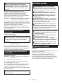
Lampki wskaźnika Pozostała
energia
akumulatora
Świeci się Wyłączony Miga
75–100%
50–75%
25–50%
0–25%
Naładować
akumulator.
Akumulator
może nie
działać
poprawnie.
WSKAZÓWKA: Zależnie od warunków użytkowania
i temperatury otoczenia, wskazywany poziom może
nieznacznie się różnić od rzeczywistego stanu nała-
dowania akumulatora.
Układ zabezpieczenia narzędzia/
akumulatora
Narzędzie jest wyposażone w układ zabezpieczenia
narzędzia/akumulatora. Układ automatycznie odcina
zasilanie silnika w celu wydłużenia trwałości narzędzia
i akumulatora. Narzędzie zostanie automatycznie
zatrzymane podczas pracy w następujących sytuacjach
związanych z narzędziem lub akumulatorem:
► Rys.3: 1. Wskaźnik akumulatora
Zabezpieczenie przed przeciążeniem
W przypadku obsługi narzędzia w sposób powodujący
pobór nadmiernie wysokiego prądu narzędzie zostanie
automatycznie zatrzymane bez żadnej sygnalizacji. W
takiej sytuacji należy wyłączyć narzędzie i zaprzestać
wykonywania czynności powodującej przeciążenie
narzędzia. Następnie należy włączyć narzędzie w celu
jego ponownego uruchomienia.
Zabezpieczenie przed przegrzaniem
W przypadku przegrzania akumulatorów lub narzędzia
zostanie ono automatycznie zatrzymane, a wskaźniki
akumulatora będą migać przez około 60 s. W takiej
sytuacji należy odczekać, aż narzędzie i akumulatory
ostygną przed ponownym włączeniem narzędzia.
Włączony Wył. Miga
Zabezpieczenie przed nadmiernym
rozładowaniem
W przypadku, gdy stan naładowania któregokolwiek z
akumulatorów osiągnie zbyt niski poziom, narzędzie
zostanie automatycznie zatrzymane i zapali się wskaź-
nik akumulatora znajdujący się na jego boku. W takiej
sytuacji należy wyjąć akumulator z narzędzia i nałado-
wać go.
Włączony Wył. Miga
Pagina se încarcă...
Pagina se încarcă...
Pagina se încarcă...
Pagina se încarcă...
Pagina se încarcă...
Pagina se încarcă...
Pagina se încarcă...
Pagina se încarcă...
Pagina se încarcă...
Pagina se încarcă...
Pagina se încarcă...
Pagina se încarcă...
Pagina se încarcă...
Pagina se încarcă...
Pagina se încarcă...
Pagina se încarcă...
Pagina se încarcă...
Pagina se încarcă...
Pagina se încarcă...
Pagina se încarcă...
Pagina se încarcă...
Pagina se încarcă...
Pagina se încarcă...
Pagina se încarcă...
Pagina se încarcă...
Pagina se încarcă...
Pagina se încarcă...
Pagina se încarcă...
Pagina se încarcă...
Pagina se încarcă...
Pagina se încarcă...
Pagina se încarcă...
Pagina se încarcă...
Pagina se încarcă...
Pagina se încarcă...
Pagina se încarcă...
Pagina se încarcă...
Pagina se încarcă...
Pagina se încarcă...
Pagina se încarcă...
Pagina se încarcă...
Pagina se încarcă...
Pagina se încarcă...
Pagina se încarcă...
Pagina se încarcă...
Pagina se încarcă...
Pagina se încarcă...
Pagina se încarcă...
Pagina se încarcă...
Pagina se încarcă...
Pagina se încarcă...
Pagina se încarcă...
Pagina se încarcă...
Pagina se încarcă...
Pagina se încarcă...
Pagina se încarcă...
Pagina se încarcă...
Pagina se încarcă...
Pagina se încarcă...
Pagina se încarcă...
Pagina se încarcă...
Pagina se încarcă...
Pagina se încarcă...
Pagina se încarcă...
Pagina se încarcă...
Pagina se încarcă...
Pagina se încarcă...
Pagina se încarcă...
-
 1
1
-
 2
2
-
 3
3
-
 4
4
-
 5
5
-
 6
6
-
 7
7
-
 8
8
-
 9
9
-
 10
10
-
 11
11
-
 12
12
-
 13
13
-
 14
14
-
 15
15
-
 16
16
-
 17
17
-
 18
18
-
 19
19
-
 20
20
-
 21
21
-
 22
22
-
 23
23
-
 24
24
-
 25
25
-
 26
26
-
 27
27
-
 28
28
-
 29
29
-
 30
30
-
 31
31
-
 32
32
-
 33
33
-
 34
34
-
 35
35
-
 36
36
-
 37
37
-
 38
38
-
 39
39
-
 40
40
-
 41
41
-
 42
42
-
 43
43
-
 44
44
-
 45
45
-
 46
46
-
 47
47
-
 48
48
-
 49
49
-
 50
50
-
 51
51
-
 52
52
-
 53
53
-
 54
54
-
 55
55
-
 56
56
-
 57
57
-
 58
58
-
 59
59
-
 60
60
-
 61
61
-
 62
62
-
 63
63
-
 64
64
-
 65
65
-
 66
66
-
 67
67
-
 68
68
-
 69
69
-
 70
70
-
 71
71
-
 72
72
-
 73
73
-
 74
74
-
 75
75
-
 76
76
-
 77
77
-
 78
78
-
 79
79
-
 80
80
-
 81
81
-
 82
82
-
 83
83
-
 84
84
-
 85
85
-
 86
86
-
 87
87
-
 88
88


în alte limbi
- slovenčina: Makita DGA700 Používateľská príručka
- polski: Makita DGA700 Instrukcja obsługi
Lucrări înrudite
-
Makita GA042G Manual de utilizare
-
Makita GA027G Manual de utilizare
-
Makita GA037G, GA038G Cordless Angle Grinder Manual de utilizare
-
Makita GA037G Manual de utilizare
-
Makita GA021G Manual de utilizare
-
Makita 9565CR Manual de utilizare
-
Makita GA048G Manual de utilizare
-
Makita GA4590 Manual de utilizare
-
-
Makita CE001G Manual de utilizare
Alte documente
-
Hikoki G23SWU2 230mm Disc Grinder Manual de utilizare
-
-
Milwaukee M12FCOT-0 Manual de utilizare
-
Crown CT23001-125HX-2 Manual de utilizare
-
Maktec MT962 Manual de utilizare
-
Tryton TMG170K Manual de utilizare
-
-
Graphite 58GE137 Manualul proprietarului