Makita GA037G, GA038G Cordless Angle Grinder Manual de utilizare
- Tip
- Manual de utilizare

Cordless
Angle
Grinder
INSTRUCTION
MANUAL
9
Akumulatorowa szlifierka
kątowa
INSTRUKCJA OBSŁUGI
23
Akkumulátoros
sarokcsiszoló
HASZNÁLATI
KÉZIKÖNYV
40
Ručná uhlová brúska
NÁVOD
NA
OBSLUHU
56
Akumulátorová úhlová
bruska
NÁVOD
K
OBSLUZE
71
Бездротова кутова
шліфувальна машина
ІНСТРУКЦІЯ З
ЕКСПЛУАТАЦІЇ
86
Polizor unghiular cu
acumulator
MANUAL DE INSTRUCŢIUNI
103
Akku-Winkelschleifer
BETRIEBSANLEITUNG
119
GA037G
GA038G
DE
RO
UK
CS
SK
HU
PL
EN

2
1
Fig.8
2 1
Fig.4
1
2
Fig.7
1
Fig.3
2
1
Fig.6
1 2
Fig.2
Fig.5
1 2
Fig.1
3

3
Fig.16
1
1
2
Fig.12
1
2
3
4
Fig.15
1
2
4 3
Fig.11
1
2
3
Fig.14
1
2
3
Fig.10
1
2
3
4
Fig.13
Fig.9
2 1

4
1
2
Fig.24
ø45
1 ø78
2
3 ø78
4
5
Fig.20
1
2 3
4
5
6
7
Fig.23
1
2
3
4
Fig.19
1
Fig.22
Fig.18
1
Fig.21
1 2
Fig.17

5
1
2
3
4
Fig.32
Fig.28
1
Fig.31
Fig.27
Fig.30
Fig.26
Fig.29
Fig.25

6
1
Fig.37
Fig.36
1
Fig.34
1 2
2
1
Fig.35
3
1
2
Fig.33

7
1
Fig.43
1
Fig.40
1 2
Fig.42
1
Fig.39
1 2
2
1
Fig.41
2
1
Fig.38

8
1
2 2 8 2 12 13 18 21
19
3 3 9 11 14 3
15 16
4 6 10 20 22
5 7 17 16 5
5 5 5
Fig.44

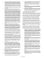
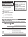
ENGLISH (Original instructions)
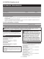
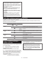
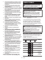
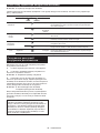
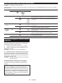
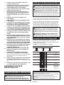
*1. With battery cartridge (BL4050F).
•
Due to our continuing program of research and development, the specifications herein are subject to change
without notice.
Specifications may differ from country to country.
The weight may differ depending on the attachment(s), including the battery cartridge. The lightest and heavi-
est combination, according to EPTA-Procedure 01/2014, are shown in the table.
•
•
Applicable battery cartridge and charger
•
Some of the battery cartridges and chargers listed above may not be available depending on your region of residence.
The tool is intended for grinding, sanding and cutting of
metal and stone materials without the use of water.
The typical A-weighted noise level determined accord-
ing to EN60745-2-3:
Model GA037G
Sound pressure level (LpA) : 88 dB(A)
Sound power level (LWA) : 99 dB (A)
Uncertainty (K) : 3 dB(A)
Model GA038G
Sound pressure level (LpA) : 87 dB(A)
Sound power level (LWA) : 98 dB (A)
Uncertainty (K) : 3 dB(A)
The vibration total value (tri-axial vector sum) deter-
mined according to EN60745-2-3:
Model GA037G
Work mode: surface grinding with normal side grip
Vibration emission (ah, AG) : 5.5 m/s2
Uncertainty (K) : 1.5 m/s2
Work mode: surface grinding with anti vibration side grip
Vibration emission (ah, AG) : 6.0 m/s2
Uncertainty (K) : 1.5 m/s2
Work mode: disc sanding with normal side grip
Vibration emission (ah, DS) : 3.0 m/s2
Uncertainty (K) : 1.5 m/s2
Work mode: disc sanding with anti vibration side grip
Vibration emission (ah, DS) : 2.5 m/s2
Uncertainty (K) : 1.5 m/s2
9 ENGLISH
NOTE: The declared noise emission value(s) has
been measured in accordance with a standard test
method and may be used for comparing one tool with
another.
NOTE: The declared noise emission value(s)
may also be used in a preliminary assessment of
exposure.
Vibration
Noise
Intended use
WARNING: Wear ear protection.
WARNING: The noise emission during actual
use of the power tool can differ from the declared
value(s) depending on the ways in which the tool is
used especially what kind of workpiece is processed.
WARNING: Be sure to identify safety mea-
sures to protect the operator that are based on an
estimation of exposure in the actual conditions of
use (taking account of all parts of the operating
cycle such as the times when the tool is switched
off and when it is running idle in addition to the
trigger time).
WARNING: Only use the battery cartridges and chargers listed above. Use of any other battery cartridges
and chargers may cause injury and/or fire.
Battery cartridge
BL4025 / BL4040 / BL4050F*
* : Recommended battery
Charger
DC40RA / DC40RB / DC40RC
Model:
GA037G
GA038G
Wheel diameter
180 mm
230 mm
Max. wheel thickness
7.2 mm
6.5 mm
Spindle thread
M14 or M16 or 5/8″ (country specific)
Rated speed (n)
7,800 min-1
6,600 min-1
Overall length
535 mm *1
Rated voltage
D.C. 36 V - 40 V max
Net weight
4.4 - 5.4 kg
4.6 - 7.4 kg
SPECIFICATIONS

Model GA038G
Work mode: surface grinding with normal side grip
Vibration emission (ah, AG) : 7.0 m/s2
Uncertainty (K) : 1.5 m/s2
Work mode: surface grinding with anti vibration side grip
Vibration emission (ah, AG) : 7.5 m/s2
Uncertainty (K) : 1.5 m/s2
Work mode: disc sanding with normal side grip
Vibration emission (ah, DS) : 2.5 m/s2 or less
Uncertainty (K) : 1.5 m/s2
Work mode: disc sanding with anti vibration side grip
Vibration emission (ah, DS) : 2.5 m/s2 or less
Uncertainty (K) : 1.5 m/s2
Cordless grinder safety warnings
Safety Warnings Common for Grinding, Sanding,
Wire Brushing, or Abrasive Cutting-Off Operations:
1.
This power tool is intended to function as a
grinder, sander, wire brush or cut-off tool. Read
all safety warnings, instructions, illustrations
and specifications provided with this power tool.
Failure to follow all instructions listed below may
result in electric shock, fire and/or serious injury.
Operations such as polishing are not recom-
mended to be performed with this power tool.
Operations for which the power tool was not designed
may create a hazard and cause personal injury.
Do not use accessories which are not specifically
designed and recommended by the tool manufac-
turer.
Just because the accessory can be attached to
your power tool, it does not assure safe operation.
The rated speed of the accessory must be at
least equal to the maximum speed marked on
the power tool. Accessories running faster than
their rated speed can break and fly apart.
The outside diameter and the thickness of your
accessory must be within the capacity rating
of your power tool. Incorrectly sized accessories
cannot be adequately guarded or controlled.
Threaded mounting of accessories must match
the grinder spindle thread. For accessories
mounted by flanges, the arbour hole of the
accessory must fit the locating diameter of the
flange.
Accessories that do not match the mounting
hardware of the power tool will run out of balance,
vibrate excessively and may cause loss of control.
Do not use a damaged accessory. Before each use
inspect the accessory such as abrasive wheels for
chips and cracks, backing pad for cracks, tear or
excess wear, wire brush for loose or cracked wires.
If power tool or accessory is dropped, inspect for
damage or install an undamaged accessory. After
inspecting and installing an accessory, position
yourself and bystanders away from the plane of the
rotating accessory and run the power tool at maxi-
mum no-load speed for one minute.
Damaged acces-
sories will normally break apart during this test time.
Wear personal protective equipment. Depending
on application, use face shield, safety goggles or
safety glasses. As appropriate, wear dust mask,
hearing protectors, gloves and workshop apron
capable of stopping small abrasive or workpiece
fragments.
The eye protection must be capable of
stopping flying debris generated by various operations.
The dust mask or respirator must be capable of filtrating
particles generated by your operation. Prolonged expo-
sure to high intensity noise may cause hearing loss.
Keep bystanders a safe distance away from work
area. Anyone entering the work area must wear
personal protective equipment.
Fragments of
workpiece or of a broken accessory may fly away and
cause injury beyond immediate area of operation.
Hold the power tool by insulated gripping
surfaces only, when performing an operation
where the cutting tool may contact hidden
wiring. Contact with a "live" wire will also make
exposed metal parts of the power tool "live" and
could give the operator an electric shock.
2.
3.
4.
5.
6.
7.
EC Declaration of Conformity
For European countries only
The EC declaration of conformity is included as Annex A
to this instruction manual.
8.
SAFETY WARNINGS
General power tool safety warnings
9.
Save all warnings and instruc-
tions for future reference.
The term "power tool" in the warnings refers to your
mains-operated (corded) power tool or battery-operated
(cordless) power tool.
10.
10
ENGLISH
WARNING: Read all safety warnings, instruc-
tions, illustrations and specifications provided
with this power tool. Failure to follow all instructions
listed below may result in electric shock, fire and/or
serious injury.
WARNING: The vibration emission during
actual use of the power tool can differ from the
declared value(s) depending on the ways in which
the tool is used especially what kind of workpiece
is processed.
WARNING: Be sure to identify safety mea-
sures to protect the operator that are based on an
estimation of exposure in the actual conditions of
use (taking account of all parts of the operating
cycle such as the times when the tool is switched
off and when it is running idle in addition to the
trigger time).
WARNING: The declared vibration emission
value is used for main applications of the power tool.
However if the power tool is used for other applica-
tions, the vibration emission value may be different.
NOTE: The declared vibration total value(s) has been
measured in accordance with a standard test method
and may be used for comparing one tool with another.
NOTE: The declared vibration total value(s) may also
be used in a preliminary assessment of exposure.

11.
Never lay the power tool down until the acces-
sory has come to a complete stop. The spinning
accessory may grab the surface and pull the
power tool out of your control.
Do not run the power tool while carrying it at
your side. Accidental contact with the spinning
accessory could snag your clothing, pulling the
accessory into your body.
Regularly clean the power tool’s air vents. The
motor’s fan will draw the dust inside the housing
and excessive accumulation of powdered metal
may cause electrical hazards.
Do not operate the power tool near flammable
materials. Sparks could ignite these materials.
Do not use accessories that require liquid
coolants. Using water or other liquid coolants
may result in electrocution or shock.
2.
The grinding surface of centre depressed
wheels must be mounted below the plane of
the guard lip. An improperly mounted wheel that
projects through the plane of the guard lip cannot
be adequately protected.
The guard must be securely attached to the
power tool and positioned for maximum safety,
so the least amount of wheel is exposed
towards the operator. The guard helps to protect
the operator from broken wheel fragments, acci-
dental contact with wheel and sparks that could
ignite clothing.
Wheels must be used only for recommended
applications. For example: do not grind with
the side of cut-off wheel. Abrasive cut-off wheels
are intended for peripheral grinding, side forces
applied to these wheels may cause them to
shatter.
Always use undamaged wheel flanges that are
of correct size and shape for your selected
wheel. Proper wheel flanges support the wheel
thus reducing the possibility of wheel breakage.
Flanges for cut-off wheels may be different from
grinding wheel flanges.
Do not use worn down wheels from larger
power tools. Wheel intended for larger power tool
is not suitable for the higher speed of a smaller
tool and may burst.
12.
3.
13.
4.
14.
15.
Kickback and Related Warnings
Kickback is a sudden reaction to a pinched or snagged
rotating wheel, backing pad, brush or any other acces-
sory. Pinching or snagging causes rapid stalling of the
rotating accessory which in turn causes the uncon-
trolled power tool to be forced in the direction opposite
of the accessory’s rotation at the point of the binding.
For example, if an abrasive wheel is snagged or
pinched by the workpiece, the edge of the wheel that is
entering into the pinch point can dig into the surface of
the material causing the wheel to climb out or kick out.
The wheel may either jump toward or away from the
operator, depending on direction of the wheel’s move-
ment at the point of pinching. Abrasive wheels may also
break under these conditions.
Kickback is the result of power tool misuse and/or
incorrect operating procedures or conditions and can be
avoided by taking proper precautions as given below.
5.
6.
Additional Safety Warnings Specific for Abrasive
Cutting-Off Operations:
1.
Do not “jam“ the cut-off wheel or apply exces-
sive pressure. Do not attempt to make an
excessive depth of cut. Overstressing the wheel
increases the loading and susceptibility to twisting
or binding of the wheel in the cut and the possibil-
ity of kickback or wheel breakage.
Do not position your body in line with and
behind the rotating wheel. When the wheel, at
the point of operation, is moving away from your
body, the possible kickback may propel the spin-
ning wheel and the power tool directly at you.
When wheel is binding or when interrupting
a cut for any reason, switch off the power
tool and hold the power tool motionless until
the wheel comes to a complete stop. Never
attempt to remove the cut-off wheel from the
cut while the wheel is in motion otherwise
kickback may occur. Investigate and take correc-
tive action to eliminate the cause of wheel binding.
Do not restart the cutting operation in the
workpiece. Let the wheel reach full speed and
carefully re-enter the cut. The wheel may bind,
walk up or kickback if the power tool is restarted in
the workpiece.
Support panels or any oversized workpiece to
minimize the risk of wheel pinching and kick-
back. Large workpieces tend to sag under their
own weight. Supports must be placed under the
workpiece near the line of cut and near the edge
of the workpiece on both sides of the wheel.
Use extra caution when making a “pocket cut”
into existing walls or other blind areas. The
protruding wheel may cut gas or water pipes, elec-
trical wiring or objects that can cause kickback.
1.
Maintain a firm grip on the power tool and
position your body and arm to allow you to
resist kickback forces. Always use auxiliary
handle, if provided, for maximum control over
kickback or torque reaction during start-up.
The operator can control torque reactions or kick-
back forces, if proper precautions are taken.
Never place your hand near the rotating acces-
sory. Accessory may kickback over your hand.
Do not position your body in the area where
power tool will move if kickback occurs.
Kickback will propel the tool in direction opposite
to the wheel’s movement at the point of snagging.
Use special care when working corners, sharp
edges etc. Avoid bouncing and snagging the
accessory. Corners, sharp edges or bouncing
have a tendency to snag the rotating accessory
and cause loss of control or kickback.
Do not attach a saw chain woodcarving blade
or toothed saw blade. Such blades create fre-
quent kickback and loss of control.
2.
3.
2.
3.
4.
4.
5.
5.
Safety Warnings Specific for Grinding and Abrasive
Cutting-Off Operations:
1. Use only wheel types that are recommended
for your power tool and the specific guard
designed for the selected wheel. Wheels for
which the power tool was not designed cannot be
adequately guarded and are unsafe.
6.
11
ENGLISH

Safety Warnings Specific for Sanding Operations:
1. Do not use excessively oversized sanding
disc paper. Follow manufacturers recommen-
dations, when selecting sanding paper. Larger
sanding paper extending beyond the sanding
pad presents a laceration hazard and may cause
snagging, tearing of the disc or kickback.
Safety Warnings Specific for Wire Brushing
Operations:
17.
Do not use the tool on any materials contain-
ing asbestos.
When use cut-off wheel, always work with
the dust collecting wheel guard required by
domestic regulation.
Cutting discs must not be subjected to any
lateral pressure.
Do not use cloth work gloves during operation.
Fibers from cloth gloves may enter the tool, which
causes tool breakage.
Make sure there are no electrical cables, water
pipes, gas pipes etc. that could cause a hazard
if damaged by use of the tool.
18.
19.
20.
1.
Be aware that wire bristles are thrown by the
brush even during ordinary operation. Do not
overstress the wires by applying excessive
load to the brush. The wire bristles can easily
penetrate light clothing and/or skin.
If the use of a guard is recommended for wire
brushing, do not allow any interference of the
wire wheel or brush with the guard. Wire wheel
or brush may expand in diameter due to work load
and centrifugal forces.
21.
SAVE THESE INSTRUCTIONS.
2.
Additional Safety Warnings:
1.
When using depressed centre grinding wheels,
be sure to use only fiberglass-reinforced
wheels.
NEVER USE Stone Cup type wheels with this
grinder. This grinder is not designed for these
types of wheels and the use of such a product
may result in serious personal injury.
Be careful not to damage the spindle, the
flange (especially the installing surface) or the
lock nut. Damage to these parts could result in
wheel breakage.
Make sure the wheel is not contacting the
workpiece before the switch is turned on.
Before using the tool on an actual workpiece,
let it run for a while. Watch for vibration or
wobbling that could indicate poor installation
or a poorly balanced wheel.
Use the specified surface of the wheel to per-
form the grinding.
Do not leave the tool running. Operate the tool
only when hand-held.
Do not touch the workpiece immediately after
operation; it may be extremely hot and could
burn your skin.
Do not touch accessories immediately after
operation; it may be extremely hot and could
burn your skin.
Observe the instructions of the manufacturer
for correct mounting and use of wheels.
Handle and store wheels with care.
Do not use separate reducing bushings or
adaptors to adapt large hole abrasive wheels.
Use only flanges specified for this tool.
For tools intended to be fitted with threaded
hole wheel, ensure that the thread in the wheel
is long enough to accept the spindle length.
Check that the workpiece is properly supported.
Pay attention that the wheel continues to
rotate after the tool is switched off.
If working place is extremely hot and humid,
or badly polluted by conductive dust, use a
short-circuit breaker (30 mA) to assure opera-
tor safety.
2.
1.
Before using battery cartridge, read all instruc-
tions and cautionary markings on (1) battery
charger, (2) battery, and (3) product using
battery.
Do not disassemble or tamper the battery
cartridge. It may result in a fire, excessive heat,
or explosion.
If operating time has become excessively
shorter, stop operating immediately. It may
result in a risk of overheating, possible burns
and even an explosion.
If electrolyte gets into your eyes, rinse them
out with clear water and seek medical atten-
tion right away. It may result in loss of your
eyesight.
Do not short the battery cartridge:
3.
2.
4.
3.
5.
4.
6.
7.
5.
8.
(1)
Do not touch the terminals with any con-
ductive material.
Avoid storing battery cartridge in a con-
tainer with other metal objects such as
nails, coins, etc.
Do not expose battery cartridge to water
or rain.
(2)
9.
(3)
10.
A battery short can cause a large current
flow, overheating, possible burns and even a
breakdown.
11.
6.
Do not store and use the tool and battery car-
tridge in locations where the temperature may
reach or exceed 50 °C (122 °F).
Do not incinerate the battery cartridge even if
it is severely damaged or is completely worn
out. The battery cartridge can explode in a fire.
Do not nail, cut, crush, throw, drop the battery
cartridge, or hit against a hard object to the
battery cartridge. Such conduct may result in a
fire, excessive heat, or explosion.
Do not use a damaged battery.
12.
13.
7.
14.
15.
8.
16.
9.
12
ENGLISH
Important safety instructions for
battery cartridge
WARNING: DO NOT let comfort or familiarity
with product (gained from repeated use) replace
strict adherence to safety rules for the subject
product. MISUSE or failure to follow the safety
rules stated in this instruction manual may cause
serious personal injury.

10.
The contained lithium-ion batteries are subject to
the Dangerous Goods Legislation requirements.
For commercial transports e.g. by third parties,
forwarding agents, special requirement on pack-
aging and labeling must be observed.
For preparation of the item being shipped, consult-
ing an expert for hazardous material is required.
Please also observe possibly more detailed
national regulations.
Tape or mask off open contacts and pack up the
battery in such a manner that it cannot move
around in the packaging.
When disposing the battery cartridge, remove
it from the tool and dispose of it in a safe
place. Follow your local regulations relating to
disposal of battery.
Use the batteries only with the products
specified by Makita. Installing the batteries to
non-compliant products may result in a fire, exces-
sive heat, explosion, or leak of electrolyte.
If the tool is not used for a long period of time,
the battery must be removed from the tool.
During and after use, the battery cartridge may
take on heat which can cause burns or low
temperature burns. Pay attention to the han-
dling of hot battery cartridges.
Do not touch the terminal of the tool imme-
diately after use as it may get hot enough to
cause burns.
Do not allow chips, dust, or soil stuck into the
terminals, holes, and grooves of the battery
cartridge. It may result in poor performance or
breakdown of the tool or battery cartridge.
Unless the tool supports the use near
high-voltage electrical power lines, do not use
the battery cartridge near a high-voltage elec-
trical power lines. It may result in a malfunction
or breakdown of the tool or battery cartridge.
Keep the battery away from children.
1.
2.
Do not disassemble or tamper with the wireless unit.
Keep the wireless unit away from young children. If acci-
dentally swallowed, seek medical attention immediately.
Use the wireless unit only with Makita tools.
Do
not
expose
the
wireless
unit
to
rain
or
wet
conditions.
Do not use the wireless unit in places where
the temperature exceeds 50°C (122°F).
Do not operate the wireless unit in places where medi-
cal instruments, such as heart pace makers are nearby.
Do
not
operate
the
wireless
unit
in
places
where
automated
devices
are
nearby.
If
operated,
auto-
mated devices may develop malfunction or error.
Do not operate the wireless unit in places under
high
temperature
or
places
where
static
electric-
ity
or
electrical
noise
could
be
generated.
The wireless unit can produce electromagnetic
fields (EMF) but they are not harmful to the user.
The wireless unit is an accurate instrument. Be
careful not to drop or strike the wireless unit.
Avoid touching the terminal of the wireless
unit with bare hands or metallic materials.
Always remove the battery on the product
when installing the wireless unit into it.
When opening the lid of the slot, avoid the
place where dust and water may come into the
slot. Always keep the inlet of the slot clean.
Always insert the wireless unit in the correct direction.
Do not press the wireless activation button
on the wireless unit too hard and/or press the
button with an object with a sharp edge.
Always close the lid of the slot when operating.
Do not remove the wireless unit from the slot
while the power is being supplied to the tool.
Doing
so
may
cause
a
malfunction
of
the
wireless
unit.
Do not remove the sticker on the wireless unit.
Do not put any sticker on the wireless unit.
Do not leave the wireless unit in a place where static
electricity or electrical noise could be generated.
Do not leave the wireless unit in a place subject
to high heat, such as a car sitting in the sun.
Do not leave the wireless unit in a dusty or powdery
place or in a place corrosive gas could be generated.
Sudden change of the temperature may bedew
the wireless unit. Do not use the wireless unit
until the dew is completely dried.
When cleaning the wireless unit, gently wipe
with a dry soft cloth. Do not use benzine, thin-
ner, conductive grease or the like.
When storing the wireless unit, keep it in the
supplied case or a static-free container.
Do not insert any devices other than Makita
wireless unit into the slot on the tool.
Do
not
use
the
tool
with
the
lid
of
the
slot
damaged.
Water,
dust,
and
dirt
come
into
the
slot
may
cause
malfunction.
Do not pull and/or twist the lid of the slot more than
necessary.
Restore the lid if it comes off from the tool.
Replace the lid of the slot if it is lost or damaged.
3.
4.
5.
6.
11.
7.
12.
8.
9.
13.
10.
14.
11.
12.
15.
13.
16.
14.
15.
17.
16.
17.
18.
SAVE THESE INSTRUCTIONS.
18.
19.
20.
21.
22.
23.
Tips for maintaining maximum
battery life
24.
1.
Charge the battery cartridge before completely
discharged. Always stop tool operation and
charge the battery cartridge when you notice
less tool power.
25.
2.
Never recharge a fully charged battery cartridge.
Overcharging shortens the battery service life.
Charge the battery cartridge with room tempera-
ture at 10 °C - 40 °C (50 °F - 104 °F). Let a hot
battery cartridge cool down before charging it.
When not using the battery cartridge, remove
it from the tool or the charger.
Charge the battery cartridge if you do not use
it for a long period (more than six months).
26.
3.
27.
4.
28.
5.
29.
SAVE THESE INSTRUCTIONS.
ENGLISH
13
CAUTION: Only use genuine Makita batteries.
Use of non-genuine Makita batteries, or batteries that
have been altered, may result in the battery bursting
causing fires, personal injury and damage. It will
also void the Makita warranty for the Makita tool and
charger.
Important safety instructions for
wireless unit

The tool is equipped with a tool/battery protection system. This
system automatically cuts off power to the motor to extend tool and
battery life. The tool will automatically stop during operation if the
tool or battery is placed under one of the following conditions:
Overload protection
When the tool/battery is operated in a manner that causes
it to draw an abnormally high current, the tool automat-
ically stops without any indication. In this situation, turn
the tool off and stop the application that caused the tool to
become overloaded. Then turn the tool on to restart.
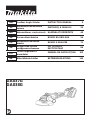
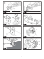
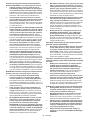
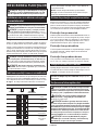
► Fig.1: 1. Red indicator 2. Button 3. Battery cartridge
To remove the battery cartridge, slide it from the tool
while sliding the button on the front of the cartridge.
To install the battery cartridge, align the tongue on the
battery cartridge with the groove in the housing and slip
it into place. Insert it all the way until it locks in place
with a little click. If you can see the red indicator on the
upper side of the button, it is not locked completely.
Overheat protection
When the tool/battery is overheated, the tool stops
automatically. Let the tool cool down before turning the
tool on again.
Overdischarge protection
When the battery capacity is not enough, the tool stops
automatically. In this case, remove the battery from the
tool and charge the battery.
Press the shaft lock to prevent spindle rotation when
installing or removing accessories.
► Fig.3: 1. Shaft lock
Press the check button on the battery cartridge to indi-
cate the remaining battery capacity. The indicator lamps
light up for a few seconds.
► Fig.2:
1. Indicator lamps 2. Check button
To prevent the switch lever from being accidentally
pulled, a lock-off lever is provided.
To start the tool, fold the lock-off lever and then pull the
switch lever.
To stop the tool, release the switch lever.
► Fig.4: 1. Lock-off lever 2. Switch lever
14
ENGLISH
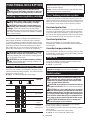
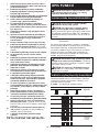
Indicator lamps
Remaining
capacity
Lighted
Off
Blinking
75% to 100%
50% to 75%
25% to 50%
0% to 25%
Charge the
battery.
The battery
may have
malfunctioned.
CAUTION: Before installing the battery car-
tridge into the tool, always check to see that the
switch lever actuates properly and returns to the
"OFF" position when released.
CAUTION:
Do not pull the switch lever hard without
pulling the lock-off lever.
This can cause switch breakage.
CAUTION:
For your safety, this tool is equipped
with lock-off lever which prevents the tool from unin-
tended starting. NEVER use the tool if it runs when
you simply pull the switch trigger without pulling the
lock-off lever. Return the tool to our authorized ser-
vice center for proper repairs BEFORE further usage.
CAUTION: NEVER tape down or defeat pur-
pose and function of lock-off lever.
Switch action
NOTICE: Never actuate the shaft lock when the
spindle is moving. The tool may be damaged.
Indicating
the
remaining
battery
capacity
Shaft lock
CAUTION: Always install the battery cartridge
fully until the red indicator cannot be seen. If not,
it may accidentally fall out of the tool, causing injury to
you or someone around you.
CAUTION: Do not install the battery cartridge
forcibly. If the cartridge does not slide in easily, it is
not being inserted correctly.
CAUTION: Always switch off the tool before
installing or removing of the battery cartridge.
CAUTION: Hold the tool and the battery car-
tridge firmly when installing or removing battery
cartridge. Failure to hold the tool and the battery
cartridge firmly may cause them to slip off your hands
and result in damage to the tool and battery cartridge
and a personal injury.
Installing or removing battery cartridge
Tool / battery protection system
CAUTION: Always be sure that the tool is
switched off and the battery cartridge is removed
before adjusting or checking function on the tool.
NOTE: Depending on the conditions of use and the
ambient temperature, the indication may differ slightly
from the actual capacity.
NOTE: The first (far left) indicator lamp will blink when
the battery protection system works.
FUNCTIONAL DESCRIPTION

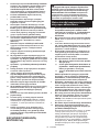
Mount the wheel guard with the protrusions on the
wheel guard band aligned with the notches on the bear-
ing box. Then rotate the wheel guard to such an angle
that it can protect the operator according to work.
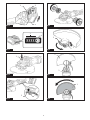
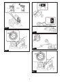
► Fig.7: 1. Wheel guard 2. Bearing box
► Fig.8: 1. Wheel guard
Securely tighten the nut using a spanner, and then close the
lever in direction of the arrow to fasten the wheel guard. If
the lever is too tight or too loose to fasten the wheel guard,
open the lever and then loosen or tighten the nut using the
spanner to adjust the tightening of the wheel guard band.
► Fig.9: 1. Nut 2. Lever
To remove wheel guard, follow the installation proce-
dure in reverse.
When using an abrasive cut-off /
diamond wheel
Optional accessory
When installing the battery cartridge while pulling the
switch lever, the tool does not start.
To start the tool, first release the switch lever. Then pull
the lock-off lever, and pull the switch lever.
Electronic torque control function
The tool electronically detects situations where the wheel
or accessory may be at risk to be bound. In the situation,
the tool is automatically shut off to prevent further rotation
of the spindle (it does not prevent kickback).
To restart the tool, switch off the tool first, remove the
cause of sudden drop in the rotation speed, and then
turn the tool on.
Soft start feature
Soft start feature reduces starting reaction.
Electric brake
Electric brake is activated after the tool is switched off.
The brake does not work when the power supply is shut
down, such as the battery is removed accidentally, with
the switch still on.
Mount the wheel guard with the protrusions on the
wheel guard band aligned with the notches on the bear-
ing box. Then rotate the wheel guard to such an angle
that it can protect the operator according to work. Be
sure to tighten the screw securely.
To remove wheel guard, follow the installation proce-
dure in reverse.
► Fig.10: 1. Wheel guard 2. Bearing box 3. Screw
ASSEMBLY
Installing side grip (handle)
Optional accessory
Screw the side grip securely on the position of the tool
as shown in the figure.
► Fig.5
Mount the inner flange onto the spindle.
Make sure to fit the dented part of the inner flange onto
the straight part at the bottom of the spindle.
Fit the wheel/ disc on the inner flange and screw the
lock nut with its protrusion facing downward (facing
towards the wheel).
► Fig.11: 1. Lock nut 2. Depressed center wheel
3. Inner flange 4. Mounting part
To tighten the lock nut, press the shaft lock firmly so
that the spindle cannot revolve, then use the lock nut
wrench and securely tighten clockwise.
► Fig.12: 1. Lock nut wrench 2. Shaft lock
To remove the wheel, follow the installation procedure
in reverse.
ENGLISH
When using a depressed center
wheel / flap disc / flex wheel / wire
wheel brush
Loosen the nut, and then pull the lever in the direction
of the arrow.
► Fig.6: 1. Nut 2. Lever
15
WARNING: The wheel guard must be fitted
on the tool so that the closed side of the guard
always points toward the operator.
Installing or removing wheel guard
(For depressed center wheel, flap disc,
flex wheel, wire wheel brush / abrasive
cut-off wheel, diamond wheel)
CAUTION: Make sure that the mounting part
of the inner flange fits into the inner diameter of
the depressed center wheel / flap disc perfectly.
Mounting the inner flange on the wrong side may
result in the dangerous vibration.
WARNING: When using a depressed center
wheel or flap disc, the wheel guard must be fitted
on the tool so that the closed side of the guard
always points toward the operator.
CAUTION: Always be sure that the side grip is
installed securely before operation.
Installing or removing depressed
center wheel or flap disc
CAUTION: Always be sure that the tool is
switched off and the battery cartridge is removed
before adjusting or checking function on the tool.
WARNING: Be sure to use only the special
wheel guard designed for use with cut-off wheels.
(In some European countries, when using a diamond
wheel, the ordinary guard can be used. Follow the
regulations in your country.)
Accidental re-start preventive
function

Installing or removing flex wheel
Optional accessory
Optional accessory
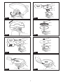
► Fig.13: 1. Lock nut 2. Flex wheel 3. Back up pad
4. Inner flange
Follow instructions for depressed center wheel but also
use back up pad over wheel. See order of assembly on
accessories page in this manual.
Installing or removing abrasive disc
Optional accessory
► Fig.14: 1. Sanding lock nut 2. Abrasive disc
3. Rubber pad
1. Mount the rubber pad onto the spindle.
2. Fit the disc on the rubber pad and screw the sand-
ing lock nut onto the spindle.
3. Hold the spindle with the shaft lock, and securely
tighten the sanding lock nut clockwise with the lock nut
wrench.
To remove the disc, follow the installation procedure in
reverse.
Mount the inner flange onto the spindle.
Fit the wheel / disc on the inner flange and screw the
lock nut onto the spindle.
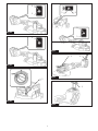
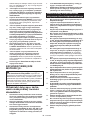
► Fig.19: 1. Lock nut 2. Abrasive cut-off wheel / dia-
mond wheel 3. Inner flange 4. Wheel guard
for abrasive cut-off wheel / diamond wheel
For Australia and New Zealand
► Fig.20: 1. Lock nut 2. Outer flange 78 3. Abrasive
cut-off wheel / diamond wheel 4. Inner
flange 78 5. Wheel guard for abrasive cut-
off wheel / diamond wheel
Installing wire cup brush
Optional accessory
Installing or removing Ezynut
Optional accessory
Only for tools with M14 spindle thread.
► Fig.21: 1. Wire cup brush
Remove the battery cartridge and place the tool upside
down allowing easy access to spindle.
Remove any accessories on spindle. Thread wire cup
brush onto spindle and tighten with supplied wrench.
Installing wire wheel brush
Optional accessory
Mount inner flange, abrasive wheel and Ezynut onto the
spindle so that Makita Logo on Ezynut faces outside.
► Fig.15: 1. Ezynut 2. Abrasive wheel 3. Inner flange
4. Spindle
Press shaft lock firmly and tighten Ezynut by turning the
abrasive wheel clockwise as far as it turns.
► Fig.16: 1. Shaft lock
To loosen the Ezynut, turn the outside ring of Ezynut
counterclockwise.
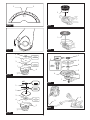
► Fig.22: 1. Wire wheel brush
Remove the battery cartridge and place the tool upside
down allowing easy access to spindle.
Remove any accessories on spindle. Thread wire wheel
brush onto spindle and tighten with the wrenches.
► Fig.17: 1. Arrow 2. Notch
► Fig.18
16
ENGLISH
NOTE: Ezynut can be loosened by hand as long
as the arrow points the notch. Otherwise a lock nut
wrench is required to loosen it. Insert one pin of the
wrench into a hole and turn Ezynut counterclockwise.
CAUTION: Do not use wire wheel brush that
is damaged, or which is out of balance. Use of
damaged wire wheel brush could increase potential
for injury from contact with broken wires.
CAUTION: ALWAYS use guard with wire
wheel brushes, assuring diameter of wheel fits
inside guard. Wheel can shatter during use and
guard helps to reduce chances of personal injury.
CAUTION: Do not use Ezynut with Super
Flange or angle grinder with “F” on the end of
the model No. Those flanges are so thick that the
entire thread cannot be retained by the spindle.
CAUTION: Do not use brush that is damaged,
or which is out of balance. Use of damaged brush
could increase potential for injury from contact with
broken brush wires.
NOTE: Use sander accessories specified in this man-
ual. These must be purchased separately.
WARNING: When using an abrasive cut-off
/ diamond wheel, be sure to use only the special
wheel guard designed for use with cut-off wheels.
(In some European countries, when using a diamond
wheel, the ordinary guard can be used. Follow the
regulations in your country.)
WARNING: NEVER use cut-off wheel for side
grinding.
WARNING: Always use supplied guard when
flex wheel is on tool. Wheel can shatter during use
and guard helps to reduce chances of personal injury.
Installing abrasive cut-off / diamond
wheel

Installing offset diamond wheel
Optional accessory
With optional accessories, you can use this tool for
planing concrete surface.
Grinding and sanding operation
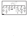
► Fig.25
Turn the tool on and then apply the wheel or disc to the
workpiece.
In general, keep the edge of the wheel or disc at an
angle of about 15° to the workpiece surface.
During the break-in period with a new wheel, do not
work the grinder in forward direction or it may cut into
the workpiece. Once the edge of the wheel has been
rounded off by use, the wheel may be worked in both
forward and backward direction.
Remove the battery cartridge and install the dust col-
lecting wheel guard for the offset diamond wheel.
Mount the inner flange onto the spindle. Fit the offset diamond
wheel on the inner flange and tighten the lock nut onto the spindle.
► Fig.23: 1. Lock nut 2. Convex section 3. Offset
diamond wheel 4. Inner flange 5. Spindle
6. Dust collecting wheel guard for the offset
diamond wheel 7. Shaft lock
Connecting a vacuum cleaner
Optional accessory
Optional accessory
To avoid dusty environment caused by masonry cutting,
use a dust collecting wheel guard and a vacuum cleaner.
Refer to the instruction manual attached to the dust
collecting wheel guard for assembling and using it.
► Fig.24: 1. Dust collecting wheel guard 2. Hose of
the vacuum cleaner
OPERATION
Usage example: operation with abrasive cut-off
wheel
► Fig.26
Usage example: operation with diamond wheel
► Fig.27
17
ENGLISH
WARNING: It should never be necessary to
force the tool. The weight of the tool applies ade-
quate pressure. Forcing and excessive pressure
could cause dangerous wheel breakage.
WARNING: ALWAYS replace wheel if tool is
dropped while grinding.
WARNING: NEVER bang or hit grinding disc
or wheel onto work.
WARNING: Avoid bouncing and snagging
the wheel, especially when working corners,
sharp edges etc. This can cause loss of control and
kickback.
WARNING: NEVER use tool with wood cutting
blades and other saw blades. Such blades when
used on a grinder frequently kick and cause loss of
control leading to personal injury.
WARNING: Do not "jam" the wheel or apply
excessive pressure. Do not attempt to make an
excessive depth of cut. Overstressing the wheel
increases the loading and susceptibility to twisting
or binding of the wheel in the cut and the possibility
of kickback, wheel breakage and overheating of the
motor may occur.
WARNING: Do not start the cutting operation
in the workpiece. Let the wheel reach full speed
and carefully enter into the cut moving the tool
forward over the workpiece surface. The wheel
may bind, walk up or kickback if the power tool is
started in the workpiece.
WARNING: During cutting operations, never
change the angle of the wheel. Placing side pres-
sure on the cut-off wheel (as in grinding) will cause
the wheel to crack and break, causing serious per-
sonal injury.
WARNING: A diamond wheel shall be oper-
ated perpendicular to the material being cut.
WARNING: Never vacuum metal particles cre-
ated by grinding/cutting/sanding operation. Metal
particles created by such operation are so hot that they
ignite dust and the filter inside the vacuum cleaner.
Operation with abrasive cut-off /
diamond wheel
CAUTION:
Dust collecting wheel guard for the offset
diamond wheel is only for use in planing concrete surface
with a offset diamond wheel. Do not use this guard with
any other cutting accessory or for any other purpose.
CAUTION: Before operation, make sure that a
vacuum cleaner is connected to the tool and turned on.
WARNING: For offset diamond wheels that
are 7 mm or thinner, place the convex section of
the lock nut upwards and attach to the spindle.
CAUTION: Never switch on the tool when it
is in contact with the workpiece, it may cause an
injury to operator.
CAUTION: Always wear safety goggles or a
face shield during operation.
CAUTION: After operation, always switch off
the tool and wait until the wheel has come to a
complete stop before putting the tool down.
CAUTION: ALWAYS hold the tool firmly with
one hand on housing and the other on the side
grip (handle).

Operation with wire cup brush
Optional accessory
1. Open the lid on the tool as shown in the figure.
► Fig.31: 1. Lid
2.
Insert the wireless unit to the slot and then close the lid.
When inserting the wireless unit, align the projections
with the recessed portions on the slot.
► Fig.32: 1. Wireless unit 2. Projection 3. Lid
4. Recessed portion
When removing the wireless unit, open the lid slowly. The hooks on
the back of the lid will lift the wireless unit as you pull up the lid.
► Fig.33: 1. Wireless unit 2. Hook 3. Lid
After removing the wireless unit, keep it in the supplied
case or a static-free container.
Usage example: operation with wire cup brush
► Fig.28
Operation with wire wheel brush
Optional accessory
Usage example: operation with wire wheel brush
► Fig.29
Tool
registration
for
the
vacuum
cleaner
The wireless activation function enables clean and com-
fortable operation. By connecting a supported vacuum
cleaner to the tool, you can run the vacuum cleaner
automatically along with the switch operation of the tool.
► Fig.30
To
use
the
wireless
activation
function,
prepare
following
items:
If you wish to activate the vacuum cleaner along with the switch
operation of the tool, finish the tool registration beforehand.
1.
Install the batteries to the vacuum cleaner and the tool.
2.
Set
the
stand-by
switch
on
the
vacuum
cleaner
to
"AUTO".
► Fig.34: 1. Stand-by switch
3.
Press the wireless activation button on the vacuum cleaner for
3 seconds until the wireless activation lamp blinks in green. And then
press the wireless activation button on the tool in the same way.
► Fig.35: 1. Wireless activation button 2. Wireless
activation lamp
If the vacuum cleaner and the tool are linked success-
fully, the wireless activation lamps will light up in green
for 2 seconds and start blinking in blue.
•
•
A wireless unit (optional accessory)
A vacuum cleaner which supports the wireless
activation function
The overview of the wireless activation function setting is
as follows. Refer to each section for detail procedures.
1.
2.
3.
Installing the wireless unit
Tool registration for the vacuum cleaner
Starting the wireless activation function
Installing the wireless unit
Optional accessory
18
ENGLISH
CAUTION: Place the tool on a flat and stable
surface when installing the wireless unit.
NOTE:
The wireless activation lamps finish blinking in green
after 20 seconds elapsed. Press the wireless activation button
on the tool while the wireless activation lamp on the cleaner is
blinking. If the wireless activation lamp does not blink in green,
push the wireless activation button briefly and hold it down again.
NOTE:
When performing two or more tool registrations for
one vacuum cleaner, finish the tool registration one by one.
What you can do with the wireless
activation function
NOTE:
A Makita vacuum cleaner supporting the wireless
activation function is required for the tool registration.
NOTE: Finish installing the wireless unit to the tool
before starting the tool registration.
NOTE:
During the tool registration, do not pull the switch
trigger
or
turn
on
the
power
switch
on
the
vacuum
cleaner.
NOTE: Refer to the instruction manual of the vacuum
cleaner, too.
WIRELESS ACTIVATION
FUNCTION
NOTICE: Always use the hooks on the back of
the lid when removing the wireless unit. If the
hooks do not catch the wireless unit, close the lid
completely and open it slowly again.
NOTICE:
Avoid applying too much pressure which
causes over bending of wires when using wire
wheel brush. It may lead to premature breakage.
CAUTION: Check operation of wire wheel
brush by running tool with no load, insuring that no
one is in front of or in line with the wire wheel brush.
NOTICE: Avoid applying too much pressure
which causes over bending of wires when using
brush. It may lead to premature breakage.
CAUTION: Check operation of brush by run-
ning tool with no load, insuring that no one is in
front of or in line with brush.
NOTICE:
Clean the dust and dirt on the tool before
installing the wireless unit. Dust or dirt may cause
malfunction if it comes into the slot of the wireless unit.
NOTICE:
To prevent the malfunction caused by static,
touch a static discharging material, such as a metal part
of the tool, before picking up the wireless unit.
NOTICE:
When installing the wireless unit, always
be sure that the wireless unit is inserted in the cor-
rect direction and the lid is completely closed.

5. Pull the switch trigger of the tool. Check if the vac-
uum cleaner runs while the switch trigger is being pulled.
To stop the wireless activation of the vacuum cleaner,
push the wireless activation button on the tool.
After registering a tool to the vacuum cleaner, the vacuum cleaner
will automatically runs along with the switch operation of the tool.
1. Install the wireless unit to the tool.
2.
Connect the hose of the vacuum cleaner with the tool.
► Fig.36
3.
Set the stand-by switch on the vacuum cleaner to "AUTO".
► Fig.37: 1. Stand-by switch
4. Push the wireless activation button on the tool
briefly. The wireless activation lamp will blink in blue.
► Fig.38: 1. Wireless activation button 2. Wireless
activation lamp
► Fig.39: 1. Wireless activation lamp
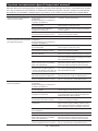
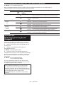
The wireless activation lamp shows the status of the wireless activation function. Refer to the table below for the
meaning of the lamp status.
If the cancellation is performed successfully, the wire-
less activation lamps will light up in red for 2 seconds
and start blinking in blue.
Perform the following procedure when cancelling the
tool registration for the vacuum cleaner.
1.
Install the batteries to the vacuum cleaner and the tool.
2.
Set
the
stand-by
switch
on
the
vacuum
cleaner
to
"AUTO".
► Fig.40: 1. Stand-by switch
3. Press the wireless activation button on the vac-
uum cleaner for 6 seconds. The wireless activation
lamp blinks in green and then become red. After that,
press the wireless activation button on the tool in the
same way.
► Fig.41: 1. Wireless activation button 2. Wireless
activation lamp 19
ENGLISH
NOTE: The wireless activation lamps finish blinking in
red after 20 seconds elapsed. Press the wireless acti-
vation button on the tool while the wireless activation
lamp on the cleaner is blinking. If the wireless acti-
vation lamp does not blink in red, push the wireless
activation button briefly and hold it down again.
Cancelling tool registration for the
vacuum cleaner
Status
Wireless activation lamp
Description
Color
On
Blinking
Duration
Standby
Blue
2 hours
The wireless activation of the vacuum cleaner is available. The
lamp will automatically turn off when no operation is performed
for 2 hours.
When
the tool is
running.
The wireless activation of the vacuum cleaner is available and the
tool is running.
Tool
registration
Green
20 seconds
Ready for the tool registration. Waiting for the registration by the
vacuum cleaner.
2 seconds
The tool registration has been finished. The wireless activation
lamp will start blinking in blue.
Cancelling
tool
registration
Red
20 seconds
Ready for the cancellation of the tool registration. Waiting for the
cancellation by the vacuum cleaner.
2 seconds
The cancellation of the tool registration has been finished. The
wireless activation lamp will start blinking in blue.
Others
Red
3 seconds
The power is supplied to the wireless unit and the wireless activa-
tion function is starting up.
Off
-
-
The wireless activation of the vacuum cleaner is stopped.
Description of the wireless activation lamp status
NOTE: The wireless activation lamp on the tool will
stop blinking in blue when there is no operation for
2 hours. In this case, set the stand-by switch on the
vacuum cleaner to "AUTO" and push the wireless
activation button on the tool again.
NOTE: The vacuum cleaner starts/stops with a delay.
There is a time lag when the vacuum cleaner detects
a switch operation of the tool.
NOTE:
The transmission distance of the wireless unit may
vary
depending
on
the
location
and
surrounding
circumstances.
NOTE: When two or more tools are registered to one
vacuum cleaner, the vacuum cleaner may start run-
ning even if you do not pull the switch trigger because
another user is using the wireless activation function.
NOTE: Finish the tool registration for the vacuum
cleaner prior to the wireless activation.
NOTE: Refer to the instruction manual of the vacuum
cleaner, too.
Starting the wireless activation function

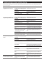
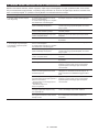
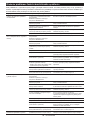
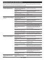
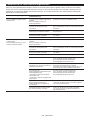
Before asking for repairs, conduct your own inspection first. If you find a problem that is not explained in the manual,
do not attempt to dismantle the tool. Instead, ask Makita Authorized Service Centers, always using Makita replace-
ment parts for repairs.
20 ENGLISH
State of abnormality
Probable cause (malfunction)
Remedy
The wireless activation lamp does
not light/blink.
The wireless unit is not installed into the tool.
The wireless unit is improperly installed
into the tool.
Install the wireless unit correctly.
The terminal of the wireless unit and/or
the slot is dirty.
Gently wipe off dust and dirt on the terminal of the
wireless unit and clean the slot.
The wireless activation button on the
tool has not been pushed.
Push the wireless activation button on the tool
briefly.
The stand-by switch on the vacuum
cleaner is not set to "AUTO".
Set the stand-by switch on the vacuum cleaner to
"AUTO".
No power supply
Supply
the
power
to
the
tool
and
the
vacuum
cleaner.
Cannot finish tool registration / can-
celling tool registration successfully.
The wireless unit is not installed into the tool.
The wireless unit is improperly installed
into the tool.
Install the wireless unit correctly.
The terminal of the wireless unit and/or
the slot is dirty.
Gently wipe off dust and dirt on the terminal of the
wireless unit and clean the slot.
The stand-by switch on the vacuum
cleaner is not set to "AUTO".
Set the stand-by switch on the vacuum cleaner to
"AUTO".
No power supply
Supply
the
power
to
the
tool
and
the
vacuum
cleaner.
Incorrect operation
Push the wireless activation button briefly and perform
the tool registration/cancellation procedures again.
The tool and vacuum cleaner are away
from each other (out of the transmission
range).
Get the tool and vacuum cleaner closer to each other.
The maximum transmission distance is approximately 10
m however it may vary according to the circumstances.
Before
finishing
the
tool
registration/cancellation;
-
the switch
trigger on
the tool
is pulled
or;
-
the power button on the vacuum
cleaner is turned on.
Push the wireless activation button briefly and
perform the tool registration/cancellation procedures
again.
The tool registration procedures for the
tool or vacuum cleaner have not finished.
Perform the tool registration procedures for both the
tool and the vacuum cleaner at the same timing.
Radio disturbance by other appliances
which generate high-intensity radio waves.
Keep the tool and vacuum cleaner away from the appli-
ances such as Wi-Fi devices and microwave ovens.
The vacuum cleaner does not run
along with the switch operation of
the tool.
The wireless unit is not installed into the tool.
The wireless unit is improperly installed
into the tool.
Install the wireless unit correctly.
The terminal of the wireless unit and/or
the slot is dirty.
Gently wipe off dust and dirt on the terminal of the
wireless unit and clean the slot.
The wireless activation button on the
tool has not been pushed.
Push the wireless activation button briefly and make
sure that the wireless activation lamp is blinking in blue.
The stand-by switch on the vacuum
cleaner is not set to "AUTO".
Set the stand-by switch on the vacuum cleaner to
"AUTO".
More than 10 tools are registered to the
vacuum cleaner.
Perform
the
tool
registration
again.
If more than 10 tools are registered to the vacuum cleaner,
the tool registered earliest will be cancelled automatically.
The vacuum cleaner erased all tool
registrations.
Perform the tool registration again.
No power supply
Supply the power to the tool and the vacuum
cleaner.
The tool and vacuum cleaner are away
from each other (out of the transmission
range).
Get the tool and vacuum cleaner closer each other.
The maximum transmission distance is approxi-
mately 10 m however it may vary according to the
circumstances.
Radio disturbance by other appliances
which generate high-intensity radio
waves.
Keep the tool and vacuum cleaner away from the
appliances such as Wi-Fi devices and microwave
ovens.
The vacuum cleaner runs while the
tool's switch trigger is not pulled.
Other users are using the wireless
activation of the vacuum cleaner with
their tools.
Turn off the wireless activation button of the other
tools or cancel the tool registration of the other
tools.
Troubleshooting for wireless activation function
Pagina se încarcă...
Pagina se încarcă...
Pagina se încarcă...
Pagina se încarcă...
Pagina se încarcă...
Pagina se încarcă...
Pagina se încarcă...
Pagina se încarcă...
Pagina se încarcă...
Pagina se încarcă...
Pagina se încarcă...
Pagina se încarcă...
Pagina se încarcă...
Pagina se încarcă...
Pagina se încarcă...
Pagina se încarcă...
Pagina se încarcă...
Pagina se încarcă...
Pagina se încarcă...
Pagina se încarcă...
Pagina se încarcă...
Pagina se încarcă...
Pagina se încarcă...
Pagina se încarcă...
Pagina se încarcă...
Pagina se încarcă...
Pagina se încarcă...
Pagina se încarcă...
Pagina se încarcă...
Pagina se încarcă...
Pagina se încarcă...
Pagina se încarcă...
Pagina se încarcă...
Pagina se încarcă...
Pagina se încarcă...
Pagina se încarcă...
Pagina se încarcă...
Pagina se încarcă...
Pagina se încarcă...
Pagina se încarcă...
Pagina se încarcă...
Pagina se încarcă...
Pagina se încarcă...
Pagina se încarcă...
Pagina se încarcă...
Pagina se încarcă...
Pagina se încarcă...
Pagina se încarcă...
Pagina se încarcă...
Pagina se încarcă...
Pagina se încarcă...
Pagina se încarcă...
Pagina se încarcă...
Pagina se încarcă...
Pagina se încarcă...
Pagina se încarcă...
Pagina se încarcă...
Pagina se încarcă...
Pagina se încarcă...
Pagina se încarcă...
Pagina se încarcă...
Pagina se încarcă...
Pagina se încarcă...
Pagina se încarcă...
Pagina se încarcă...
Pagina se încarcă...
Pagina se încarcă...
Pagina se încarcă...
Pagina se încarcă...
Pagina se încarcă...
Pagina se încarcă...
Pagina se încarcă...
Pagina se încarcă...
Pagina se încarcă...
Pagina se încarcă...
Pagina se încarcă...
Pagina se încarcă...
Pagina se încarcă...
Pagina se încarcă...
Pagina se încarcă...
Pagina se încarcă...
Pagina se încarcă...
Pagina se încarcă...
Pagina se încarcă...
Pagina se încarcă...
Pagina se încarcă...
Pagina se încarcă...
Pagina se încarcă...
Pagina se încarcă...
Pagina se încarcă...
Pagina se încarcă...
Pagina se încarcă...
Pagina se încarcă...
Pagina se încarcă...
Pagina se încarcă...
Pagina se încarcă...
Pagina se încarcă...
Pagina se încarcă...
Pagina se încarcă...
Pagina se încarcă...
Pagina se încarcă...
Pagina se încarcă...
Pagina se încarcă...
Pagina se încarcă...
Pagina se încarcă...
Pagina se încarcă...
Pagina se încarcă...
Pagina se încarcă...
Pagina se încarcă...
Pagina se încarcă...
Pagina se încarcă...
Pagina se încarcă...
Pagina se încarcă...
Pagina se încarcă...
Pagina se încarcă...
Pagina se încarcă...
-
 1
1
-
 2
2
-
 3
3
-
 4
4
-
 5
5
-
 6
6
-
 7
7
-
 8
8
-
 9
9
-
 10
10
-
 11
11
-
 12
12
-
 13
13
-
 14
14
-
 15
15
-
 16
16
-
 17
17
-
 18
18
-
 19
19
-
 20
20
-
 21
21
-
 22
22
-
 23
23
-
 24
24
-
 25
25
-
 26
26
-
 27
27
-
 28
28
-
 29
29
-
 30
30
-
 31
31
-
 32
32
-
 33
33
-
 34
34
-
 35
35
-
 36
36
-
 37
37
-
 38
38
-
 39
39
-
 40
40
-
 41
41
-
 42
42
-
 43
43
-
 44
44
-
 45
45
-
 46
46
-
 47
47
-
 48
48
-
 49
49
-
 50
50
-
 51
51
-
 52
52
-
 53
53
-
 54
54
-
 55
55
-
 56
56
-
 57
57
-
 58
58
-
 59
59
-
 60
60
-
 61
61
-
 62
62
-
 63
63
-
 64
64
-
 65
65
-
 66
66
-
 67
67
-
 68
68
-
 69
69
-
 70
70
-
 71
71
-
 72
72
-
 73
73
-
 74
74
-
 75
75
-
 76
76
-
 77
77
-
 78
78
-
 79
79
-
 80
80
-
 81
81
-
 82
82
-
 83
83
-
 84
84
-
 85
85
-
 86
86
-
 87
87
-
 88
88
-
 89
89
-
 90
90
-
 91
91
-
 92
92
-
 93
93
-
 94
94
-
 95
95
-
 96
96
-
 97
97
-
 98
98
-
 99
99
-
 100
100
-
 101
101
-
 102
102
-
 103
103
-
 104
104
-
 105
105
-
 106
106
-
 107
107
-
 108
108
-
 109
109
-
 110
110
-
 111
111
-
 112
112
-
 113
113
-
 114
114
-
 115
115
-
 116
116
-
 117
117
-
 118
118
-
 119
119
-
 120
120
-
 121
121
-
 122
122
-
 123
123
-
 124
124
-
 125
125
-
 126
126
-
 127
127
-
 128
128
-
 129
129
-
 130
130
-
 131
131
-
 132
132
-
 133
133
-
 134
134
-
 135
135
-
 136
136


Makita GA037G, GA038G Cordless Angle Grinder Manual de utilizare
- Tip
- Manual de utilizare
în alte limbi
Lucrări înrudite
-
Makita GA037G Manual de utilizare
-
Makita GA039G Manual de utilizare
-
Makita CE002G Manual de utilizare
-
-
-
Makita GA027G Manual de utilizare
-
Makita GA021G Manual de utilizare
-
-
Makita CE001G Manual de utilizare
-
Makita GA042G Manual de utilizare