Mellanox Technologies
www.mellanox.com
Mellanox SwitchX and SwitchX®-2
1U Switch Systems Hardware User
Manual
Models: SX1012/SX1012X/SX1016/SX1024/SX1036/SX1400
Rev 1.4

Mellanox Technologies
350 Oakmead Parkway Suite 100
Sunnyvale, CA 94085
U.S.A.
www.mellanox.com
Tel: (408) 970-3400
Fax: (408) 970-3403
© Copyright 2017. Mellanox Technologies Ltd . All Rights Reserved .
Mellanox®, Mellanox logo, Accelio®, BridgeX®, CloudX logo, CompustorX®, Connect -IB®, ConnectX®,
CoolBox®, CORE-Direct® , EZchip®, EZchip logo, EZappliance®, EZdesign® , EZdriver®, EZsystem®,
GPUDirect®, InfiniHost®, InfiniBridge®, InfiniScale®, Kotura®, Kotura logo, Mellanox CloudRack® , Mellanox
CloudXMellanox® , Mellanox Federal Systems® , Mellanox HostDirect® , Mellanox Multi-Host®, Mellanox Open
Ethernet®, Mellanox OpenCloud® , Mellanox OpenCloud Logo® , Mellanox PeerDirect® , Mellanox ScalableHPC® ,
Mellanox StorageX®, Mellanox TuneX® , Mellanox Connect Accelerate Outperform logo , Mellanox Virtual Modular
Switch®, MetroDX®, MetroX®, MLNX-OS®, NP-1c®, NP-2®, NP-3®, Open Ethernet logo, PhyX®, PlatformX®,
PSIPHY®, SiPhy®, StoreX®, SwitchX®, Tilera®, Tilera logo, TestX®, TuneX®, The Generation of Open Ethernet
logo, UFM®, Unbreakable Link® , Virtual Protocol Interconnect®, Voltaire® and Voltaire logo are registered
trademarks of Mellanox Technologies , Ltd.
All other trademarks are property of their respective owners .
For the most updated list of Mellanox trademarks, visit http://www.mellanox.com/page/trademarks
NOTE:
THIS HARDWARE, SOFTWARE OR TEST SUITE PRODUCT (“PRODUCT(S)”) AND ITS RELATED
DOCUMENTATION ARE PROVIDED BY MELLANOX TECHNOLOGIES “AS-IS” WITH ALL FAULTS OF ANY
KIND AND SOLELY FOR THE PURPOSE OF AIDING THE CUSTOMER IN TESTING APPLICATIONS THAT
USE THE PRODUCTS IN DESIGNATED SOLUTIONS. THE CUSTOMER'S MANUFACTURING TEST
ENVIRONMENT HAS NOT MET THE STANDARDS SET BY MELLANOX TECHNOLOGIES TO FULLY
QUALIFY THE PRODUCT(S) AND/OR THE SYSTEM USING IT. THEREFORE, MELLANOX TECHNOLOGIES
CANNOT AND DOES NOT GUARANTEE OR WARRANT THAT THE PRODUCTS WILL OPERATE WITH THE
HIGHEST QUALITY. ANY EXPRESS OR IMPLIED WARRANTIES, INCLUDING, BUT NOT LIMITED TO, THE
IMPLIED WARRANTIES OF MERCHANTABILITY, FITNESS FOR A PARTICULAR PURPOSE AND
NONINFRINGEMENT ARE DISCLAIMED. IN NO EVENT SHALL MELLANOX BE LIABLE TO CUSTOMER OR
ANY THIRD PARTIES FOR ANY DIRECT, INDIRECT, SPECIAL, EXEMPLARY, OR CONSEQUENTIAL
DAMAGES OF ANY KIND (INCLUDING, BUT NOT LIMITED TO, PAYMENT FOR PROCUREMENT OF
SUBSTITUTE GOODS OR SERVICES; LOSS OF USE, DATA, OR PROFITS; OR BUSINESS INTERRUPTION)
HOWEVER CAUSED AND ON ANY THEORY OF LIABILITY, WHETHER IN CONTRACT , STRICT LIABILITY,
OR TORT (INCLUDING NEGLIGENCE OR OTHERWISE) ARISING IN ANY WAY FROM THE USE OF THE
PRODUCT(S) AND RELATED DOCUMENTATION EVEN IF ADVISED OF THE POSSIBILITY OF SUCH
DAMAGE.
Doc #: MLNX-15-4048
2Mellanox Technologies

Rev 1.4 3Mellanox Technologies
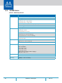
Table of Contents
Revision History . . . . . . . . . . . . . . . . . . . . . . . . . . . . . . . . . . . . . . . . . . . . . . . . . . 8
About this Manual . . . . . . . . . . . . . . . . . . . . . . . . . . . . . . . . . . . . . . . . . . . . . . . . 9
Chapter 1 Introduction to Mellanox SX10XX/SX1X00 Systems . . . . . . . . . . . 10
1.1 Overview . . . . . . . . . . . . . . . . . . . . . . . . . . . . . . . . . . . . . . . . . . . . . . . . . . . . 10
1.2 Speed and Switching . . . . . . . . . . . . . . . . . . . . . . . . . . . . . . . . . . . . . . . . . . 10
1.3 Management Interfaces and FRUs . . . . . . . . . . . . . . . . . . . . . . . . . . . . . . . 11
1.4 Features. . . . . . . . . . . . . . . . . . . . . . . . . . . . . . . . . . . . . . . . . . . . . . . . . . . . . 11
1.4.1 Network Management Feature . . . . . . . . . . . . . . . . . . . . . . . . . . . . . . . . . . 11
1.5 Certifications . . . . . . . . . . . . . . . . . . . . . . . . . . . . . . . . . . . . . . . . . . . . . . . . . 11
1.6 Ordering Information . . . . . . . . . . . . . . . . . . . . . . . . . . . . . . . . . . . . . . . . . . 12
Chapter 2 Installation . . . . . . . . . . . . . . . . . . . . . . . . . . . . . . . . . . . . . . . . . . . . 17
2.1 Safety Warnings . . . . . . . . . . . . . . . . . . . . . . . . . . . . . . . . . . . . . . . . . . . . . . 17
2.2 Air Flow . . . . . . . . . . . . . . . . . . . . . . . . . . . . . . . . . . . . . . . . . . . . . . . . . . . . . 18
2.3 Package Contents . . . . . . . . . . . . . . . . . . . . . . . . . . . . . . . . . . . . . . . . . . . . . 20
2.4 Mounting Options . . . . . . . . . . . . . . . . . . . . . . . . . . . . . . . . . . . . . . . . . . . . 21
2.4.1 19” Systems Mounting . . . . . . . . . . . . . . . . . . . . . . . . . . . . . . . . . . . . . . . . . 21
2.4.2 Side-by-Side . . . . . . . . . . . . . . . . . . . . . . . . . . . . . . . . . . . . . . . . . . . . . . . . . . 26
2.4.3 Table Top . . . . . . . . . . . . . . . . . . . . . . . . . . . . . . . . . . . . . . . . . . . . . . . . . . . . 31
2.5 Grounding . . . . . . . . . . . . . . . . . . . . . . . . . . . . . . . . . . . . . . . . . . . . . . . . . . . 33
2.6 Cable Installation . . . . . . . . . . . . . . . . . . . . . . . . . . . . . . . . . . . . . . . . . . . . . 34
2.6.1 Using a Breakout Cable. . . . . . . . . . . . . . . . . . . . . . . . . . . . . . . . . . . . . . . . . 34
2.7 SFP+ Removal Tool . . . . . . . . . . . . . . . . . . . . . . . . . . . . . . . . . . . . . . . . . . . . 37
2.8 Initial Power On . . . . . . . . . . . . . . . . . . . . . . . . . . . . . . . . . . . . . . . . . . . . . . 39
2.9 System Bring-Up . . . . . . . . . . . . . . . . . . . . . . . . . . . . . . . . . . . . . . . . . . . . . 41
2.9.1 Configuring Network Attributes. . . . . . . . . . . . . . . . . . . . . . . . . . . . . . . . . . 41
2.9.2 Remote Connection . . . . . . . . . . . . . . . . . . . . . . . . . . . . . . . . . . . . . . . . . . . 45
2.10 FRU Replacements . . . . . . . . . . . . . . . . . . . . . . . . . . . . . . . . . . . . . . . . . . . . 46
2.10.1 Power Supply and Fans . . . . . . . . . . . . . . . . . . . . . . . . . . . . . . . . . . . . . . . . 46
Chapter 3 Interfaces . . . . . . . . . . . . . . . . . . . . . . . . . . . . . . . . . . . . . . . . . . . . . 49
3.1 Supported Interfaces . . . . . . . . . . . . . . . . . . . . . . . . . . . . . . . . . . . . . . . . . . 49
3.2 Data Interfaces . . . . . . . . . . . . . . . . . . . . . . . . . . . . . . . . . . . . . . . . . . . . . . . 49
3.2.1 Speed . . . . . . . . . . . . . . . . . . . . . . . . . . . . . . . . . . . . . . . . . . . . . . . . . . . . . . . 49
3.2.2 RS232 (Console). . . . . . . . . . . . . . . . . . . . . . . . . . . . . . . . . . . . . . . . . . . . . . . 50
3.2.3 Management . . . . . . . . . . . . . . . . . . . . . . . . . . . . . . . . . . . . . . . . . . . . . . . . . 50
3.2.4 USB . . . . . . . . . . . . . . . . . . . . . . . . . . . . . . . . . . . . . . . . . . . . . . . . . . . . . . . . . 50

Rev 1.44 Mellanox Technologies
3.2.5 I2C. . . . . . . . . . . . . . . . . . . . . . . . . . . . . . . . . . . . . . . . . . . . . . . . . . . . . . . . . . 50
3.2.6 Reset Button . . . . . . . . . . . . . . . . . . . . . . . . . . . . . . . . . . . . . . . . . . . . . . . . . 51
3.3 LEDs . . . . . . . . . . . . . . . . . . . . . . . . . . . . . . . . . . . . . . . . . . . . . . . . . . . . . . . . 51
3.3.1 LED Notifications . . . . . . . . . . . . . . . . . . . . . . . . . . . . . . . . . . . . . . . . . . . . . . 51
3.4 Inventory Pull-out Tab . . . . . . . . . . . . . . . . . . . . . . . . . . . . . . . . . . . . . . . . . 56
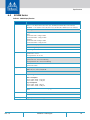
Chapter 4 Software Management . . . . . . . . . . . . . . . . . . . . . . . . . . . . . . . . . . 70
4.1 Upgrading Software . . . . . . . . . . . . . . . . . . . . . . . . . . . . . . . . . . . . . . . . . . . 70
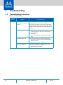
Chapter 5 Troubleshooting . . . . . . . . . . . . . . . . . . . . . . . . . . . . . . . . . . . . . . . . 74
5.1 Troubleshooting Instructions. . . . . . . . . . . . . . . . . . . . . . . . . . . . . . . . . . . . 74
Chapter 6 Specifications . . . . . . . . . . . . . . . . . . . . . . . . . . . . . . . . . . . . . . . . . . 80
6.1 SX1012 Series . . . . . . . . . . . . . . . . . . . . . . . . . . . . . . . . . . . . . . . . . . . . . . . . 80
6.2 SX1016 Series . . . . . . . . . . . . . . . . . . . . . . . . . . . . . . . . . . . . . . . . . . . . . . . . 81
6.3 SX1024 Series . . . . . . . . . . . . . . . . . . . . . . . . . . . . . . . . . . . . . . . . . . . . . . . . 82
6.4 SX1036 Series . . . . . . . . . . . . . . . . . . . . . . . . . . . . . . . . . . . . . . . . . . . . . . . . 83
Appendix A Accessory and Replacement Parts . . . . . . . . . . . . . . . . . . . . . . . 97
Appendix B Thermal Threshold Definitions . . . . . . . . . . . . . . . . . . . . . . . . . . 98
Appendix C Interface Specifications . . . . . . . . . . . . . . . . . . . . . . . . . . . . . . . . 99
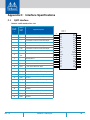
C.1 QSFP Interface . . . . . . . . . . . . . . . . . . . . . . . . . . . . . . . . . . . . . . . . . . . . . 99
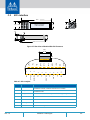
C.2 SFP+ Interface . . . . . . . . . . . . . . . . . . . . . . . . . . . . . . . . . . . . . . . . . . . . 101
C.3 RJ-45 CONSOLE and I2C Interface . . . . . . . . . . . . . . . . . . . . . . . . . . . . 103
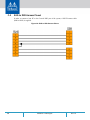
C.4 RJ45 to DB9 Harness Pinout . . . . . . . . . . . . . . . . . . . . . . . . . . . . . . . . . 104
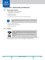
Appendix D Disassembly and Disposal . . . . . . . . . . . . . . . . . . . . . . . . . . . . . 105
D.1 Disassembly Procedure . . . . . . . . . . . . . . . . . . . . . . . . . . . . . . . . . . . . . 105
D.2 Disposal . . . . . . . . . . . . . . . . . . . . . . . . . . . . . . . . . . . . . . . . . . . . . . . . . 105
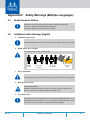
Appendix E Safety Warnings (Multiple Languages) . . . . . . . . . . . . . . . . . . . 107
E.1 Nordic Countries Notices . . . . . . . . . . . . . . . . . . . . . . . . . . . . . . . . . . . 107
E.2 Installation Safety Warnings (English) . . . . . . . . . . . . . . . . . . . . . . . . . 107
E.3 ?????? ?????? ?????? )????? ). . . . . . . . . . . . . . . . . . . . . . . . . . . . . . . . 110
E.4 安裝安全性警告 (Chinese) . . . . . . . . . . . . . . . . . . . . . . . . . . . . . . . . . 113
E.5 Avertissements de sécurité pour l'installation (French). . . . . . . . . . . 116
E.6 Installation Sicherheitshinweise(German). . . . . . . . . . . . . . . . . . . . . . 120
E.7 Advertencias de seguridad de instalación (Spanish) . . . . . . . . . . . . . 123
E.8 Предупреждения по технике безопасности при установке (Russian) 126
E.9 Avertismente privind siguranţa la instalare (Romanian) . . . . . . . . . . 129
E.10 Sigurnosna upozorenja za instaliranje (Croatian) . . . . . . . . . . . . . . . . 132
E.11 Avvertenze di sicurezza per l’installazione (italiano) . . . . . . . . . . . . . 135
E.12 Montaj Güvenlik Uyarıları (Türkçe) . . . . . . . . . . . . . . . . . . . . . . . . . . . 139

Rev 1.4 5Mellanox Technologies
List of Figures
Figure 1: Ethernet Systems Family Front Side View . . . . . . . . . . . . . . . . . . . . . . . . . . . . . . . . . . . . . . 10
Figure 2: Air Flow Direction Marking - Connector Side Inlet to Power Side Outlet . . . . . . . . . . . . . 19
Figure 3: Air Flow Direction Marking - Power Side Inlet to Connector Side Outlet . . . . . . . . . . . . . 19
Figure 4: Rack Rail Kit Parts . . . . . . . . . . . . . . . . . . . . . . . . . . . . . . . . . . . . . . . . . . . . . . . . . . . . . . . . . 22
Figure 5: Screwing on the Rail . . . . . . . . . . . . . . . . . . . . . . . . . . . . . . . . . . . . . . . . . . . . . . . . . . . . . . . 23
Figure 6: Inserting the Caged Nuts . . . . . . . . . . . . . . . . . . . . . . . . . . . . . . . . . . . . . . . . . . . . . . . . . . . .23
Figure 7: Slide the Rail into the Rail Slide . . . . . . . . . . . . . . . . . . . . . . . . . . . . . . . . . . . . . . . . . . . . . . 24
Figure 8: Installing the Slides . . . . . . . . . . . . . . . . . . . . . . . . . . . . . . . . . . . . . . . . . . . . . . . . . . . . . . . . 24
Figure 9: System Placement in the Rack . . . . . . . . . . . . . . . . . . . . . . . . . . . . . . . . . . . . . . . . . . . . . . . 25
Figure 10: Installation Completed . . . . . . . . . . . . . . . . . . . . . . . . . . . . . . . . . . . . . . . . . . . . . . . . . . . . .26
Figure 11: Installation Kit Parts for a Side by Side Installation . . . . . . . . . . . . . . . . . . . . . . . . . . . . . . 27
Figure 12: Screw on the System Mounted Rails . . . . . . . . . . . . . . . . . . . . . . . . . . . . . . . . . . . . . . . . . . 28
Figure 13: Two Systems Frame . . . . . . . . . . . . . . . . . . . . . . . . . . . . . . . . . . . . . . . . . . . . . . . . . . . . . . .29
Figure 14: Placement of Frame in the Rack . . . . . . . . . . . . . . . . . . . . . . . . . . . . . . . . . . . . . . . . . . . . . . 29
Figure 15: Placing the Spacer in the Rack . . . . . . . . . . . . . . . . . . . . . . . . . . . . . . . . . . . . . . . . . . . . . . . 30
Figure 16: Using the Spacer Bushings . . . . . . . . . . . . . . . . . . . . . . . . . . . . . . . . . . . . . . . . . . . . . . . . . . 30
Figure 17: Insert System into Frame . . . . . . . . . . . . . . . . . . . . . . . . . . . . . . . . . . . . . . . . . . . . . . . . . . . 31
Figure 18: Placing the Bumpers . . . . . . . . . . . . . . . . . . . . . . . . . . . . . . . . . . . . . . . . . . . . . . . . . . . . . . . 32
Figure 19: Cable Orientation . . . . . . . . . . . . . . . . . . . . . . . . . . . . . . . . . . . . . . . . . . . . . . . . . . . . . . . . . 34
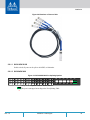
Figure 20: Breakout or Fanout Cable . . . . . . . . . . . . . . . . . . . . . . . . . . . . . . . . . . . . . . . . . . . . . . . . . . . 35
Figure 21: SX1024/SX1400 Port Splitting Options . . . . . . . . . . . . . . . . . . . . . . . . . . . . . . . . . . . . . . . . 35
Figure 22: SX1036 Port Splitting Options . . . . . . . . . . . . . . . . . . . . . . . . . . . . . . . . . . . . . . . . . . . . . . . 36
Figure 23: Examples of Port Mapping Assignment . . . . . . . . . . . . . . . . . . . . . . . . . . . . . . . . . . . . . . . . 37
Figure 24: SFP+ Removal and Insertion Tool . . . . . . . . . . . . . . . . . . . . . . . . . . . . . . . . . . . . . . . . . . . . . 38
Figure 25: System Status LEDs 5 Minutes After Power On . . . . . . . . . . . . . . . . . . . . . . . . . . . . . . . . . 40
Figure 26: Two Power Inlets - Electric Caution Notifications . . . . . . . . . . . . . . . . . . . . . . . . . . . . . . . . 41
Figure 27: Power Supply Unit Extraction . . . . . . . . . . . . . . . . . . . . . . . . . . . . . . . . . . . . . . . . . . . . . . . 47
Figure 28: PS Unit Pulled Out . . . . . . . . . . . . . . . . . . . . . . . . . . . . . . . . . . . . . . . . . . . . . . . . . . . . . . . . . 47
Figure 29: Fan Module Latches . . . . . . . . . . . . . . . . . . . . . . . . . . . . . . . . . . . . . . . . . . . . . . . . . . . . . . .48
Figure 30: System Status LEDs - Front and Rear sides . . . . . . . . . . . . . . . . . . . . . . . . . . . . . . . . . . . . . 52
Figure 31: Fan Status LED - Front and Rear sides . . . . . . . . . . . . . . . . . . . . . . . . . . . . . . . . . . . . . . . . . 53
Figure 32: Power Status LED . . . . . . . . . . . . . . . . . . . . . . . . . . . . . . . . . . . . . . . . . . . . . . . . . . . . . . . . . . 54
Figure 33: Rear Side Panel . . . . . . . . . . . . . . . . . . . . . . . . . . . . . . . . . . . . . . . . . . . . . . . . . . . . . . . . . . . 54
Figure 34: SFP+ Port LED Assignment . . . . . . . . . . . . . . . . . . . . . . . . . . . . . . . . . . . . . . . . . . . . . . . . . . 56

Rev 1.46 Mellanox Technologies
Figure 35: Port LEDs . . . . . . . . . . . . . . . . . . . . . . . . . . . . . . . . . . . . . . . . . . . . . . . . . . . . . . . . . . . . . . . . 56
Figure 36: Pull-out Tab . . . . . . . . . . . . . . . . . . . . . . . . . . . . . . . . . . . . . . . . . . . . . . . . . . . . . . . . . . . . . . 57
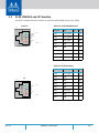
Figure 37: Rear View of Module With Pin Placement . . . . . . . . . . . . . . . . . . . . . . . . . . . . . . . . . . . . 101
Figure 38: RJ45 to DB9 Harness Pinout . . . . . . . . . . . . . . . . . . . . . . . . . . . . . . . . . . . . . . . . . . . . . . . . 104

Rev 1.4 7Mellanox Technologies
List of Tables
Table 1: Revision History Table . . . . . . . . . . . . . . . . . . . . . . . . . . . . . . . . . . . . . . . . . . . . . . . . . 8
Table 2: References . . . . . . . . . . . . . . . . . . . . . . . . . . . . . . . . . . . . . . . . . . . . . . . . . . . . . . . . . . 9
Table 3: Speed and Switching Capabilities . . . . . . . . . . . . . . . . . . . . . . . . . . . . . . . . . . . . . . . 10
Table 4: Management Interfaces and FRUs . . . . . . . . . . . . . . . . . . . . . . . . . . . . . . . . . . . . . . 11
Table 5: Ordering Part Numbers (OPNs) . . . . . . . . . . . . . . . . . . . . . . . . . . . . . . . . . . . . . . . . 12
Table 6: Air Flow Label Legend . . . . . . . . . . . . . . . . . . . . . . . . . . . . . . . . . . . . . . . . . . . . . . . . 18
Table 7: Installation Kit Options . . . . . . . . . . . . . . . . . . . . . . . . . . . . . . . . . . . . . . . . . . . . . . . 21
Table 8: Port Splitting Options . . . . . . . . . . . . . . . . . . . . . . . . . . . . . . . . . . . . . . . . . . . . . . . . 36
Table 9: Serial Terminal Program Configuration . . . . . . . . . . . . . . . . . . . . . . . . . . . . . . . . . . 42
Table 10: Configuration Wizard Session - DHCP . . . . . . . . . . . . . . . . . . . . . . . . . . . . . . . . . . . 42
Table 11: Configuration Wizard Session - Static IP Configuration . . . . . . . . . . . . . . . . . . . . . 44
Table 12: Status LEDs . . . . . . . . . . . . . . . . . . . . . . . . . . . . . . . . . . . . . . . . . . . . . . . . . . . . . . . . . 52
Table 13: System Status LED Assignments . . . . . . . . . . . . . . . . . . . . . . . . . . . . . . . . . . . . . . . . 53
Table 14: Fan Status LED Assignments . . . . . . . . . . . . . . . . . . . . . . . . . . . . . . . . . . . . . . . . . . . 53
Table 15: Power Supply Unit Status LED Assignments . . . . . . . . . . . . . . . . . . . . . . . . . . . . . . 55
Table 16: Bad Port LED Assignments . . . . . . . . . . . . . . . . . . . . . . . . . . . . . . . . . . . . . . . . . . . . 55
Table 17: Port LEDs in Ethernet System Mode . . . . . . . . . . . . . . . . . . . . . . . . . . . . . . . . . . . . 56
Table 18: Port LEDs in InfiniBand System Mode . . . . . . . . . . . . . . . . . . . . . . . . . . . . . . . . . . . 56
Table 19: Troubleshooting. . . . . . . . . . . . . . . . . . . . . . . . . . . . . . . . . . . . . . . . . . . . . . . . . . . . .74
Table 20: SX1012/SX1012X Specifications . . . . . . . . . . . . . . . . . . . . . . . . . . . . . . . . . . . . . . . . 80
Table 21: SX1016 Specifications . . . . . . . . . . . . . . . . . . . . . . . . . . . . . . . . . . . . . . . . . . . . . . . . 81
Table 22: SX1024 Specifications . . . . . . . . . . . . . . . . . . . . . . . . . . . . . . . . . . . . . . . . . . . . . . . . 82
Table 23: SX1036 Specifications . . . . . . . . . . . . . . . . . . . . . . . . . . . . . . . . . . . . . . . . . . . . . . . . 83
Table 24: OPNs for Replacement Parts. . . . . . . . . . . . . . . . . . . . . . . . . . . . . . . . . . . . . . . . . . . 97
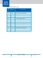
Table 25: QSFP Interface Pins 1-23 . . . . . . . . . . . . . . . . . . . . . . . . . . . . . . . . . . . . . . . . . . . . . . 99
Table 26: QSFP Interface Pins 24-38 . . . . . . . . . . . . . . . . . . . . . . . . . . . . . . . . . . . . . . . . . . . .100
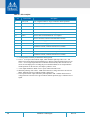
Table 27: SFP+ Interface . . . . . . . . . . . . . . . . . . . . . . . . . . . . . . . . . . . . . . . . . . . . . . . . . . . . .101
Table 28: RJ-45 CONSOLE Pinout . . . . . . . . . . . . . . . . . . . . . . . . . . . . . . . . . . . . . . . . . . . . . .103
Table 29: RJ-45 I2C Pinout . . . . . . . . . . . . . . . . . . . . . . . . . . . . . . . . . . . . . . . . . . . . . . . . . . . .103

Rev 1.48 Mellanox Technologies
Revision History
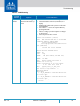
Table 1 - Revision History Table
Date Revision Description
May 2017 1.4 Updated “Specifications”
Edited
“Unit Identification LED”
September 2016 1.3 Added SX1012X
May 2017 1.4 Edited
“Unit Identification LED”
June 2015 1.2 Added Hebrew safety warnings
Added Japan VCCI Statement
Removed SX1700Updated “Specifications”
Updated “Mounting Options”
c
January 2015 1.1 Minor formatting edits
January 2015 1.0 First release of the new edition

Rev 1.4 9Mellanox Technologies
About this Manual
This manual describes the installation and basic use of the Mellanox Ethernet systems.
Intended Audience
This manual is intended for IT managers and system administrators.
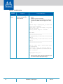
References
Table 2 - References
Document Description
SwitchX® Switch System
Hardware Release Notes
For possible hardware issues see the switch support product page. This
document can be found on the support web page for this product.
MLNX-OS® User Manual This document contains information regarding configuring and managing
MLNX-OS software-
see http://www.mellanox.com/page/mlnx_os.
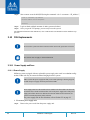
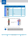
Conventions
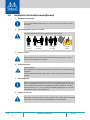
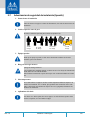
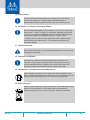
The following icons are used throughout this document to indicate information that is
important to the user.
This icon makes recommendations to the user.
This icon indicates information that is helpful to the user.
This icon indicates a situation that can potentially cause personal injury or damage to
hardware or software.
Risk of electric shock!

Rev 1.410 Mellanox Technologies
1 Introduction to Mellanox SX10XX/SX1X00 Systems
1.1 Overview
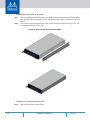
Mellanox Ethernet System Family delivers the highest performance and port density with a com-
plete chassis and fabric management solution enabling
converged data centers to operate at any
scale while reducing operational costs and infrastructure complexity. This family includes a
broad portfolio of Top-of-Rack (TOR) systems that range from 12 to 64 ports, and support 10/40/
56Gb/s per port. These systems allow IT managers to build cost-effective and scalable system
fabrics for small to large clusters up to 10's-of-thousands of nodes.
Mellanox makes fabric management as easy as it can
by providing the lowest latency and highest
bandwidth. This allows IT managers to deal with serving the company's business needs, while
solving typical networking issues such as congestion and the inefficiencies generated by adding
unnecessary rules and limitations when the network resources are sufficient.
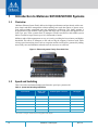
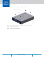
Figure 1: Ethernet Systems Family Front Side View
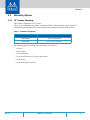
1.2 Speed and Switching
Table 3 describes maximum throughput and interface speed per system model.
Table 3 - Speed and Switching Capabilities
System Model
10GbE* SFP+
Interfaces
40/56GbE QSFP+ Interfaces Throughput
SX1012 N/A 12 1.34Tb/s
SX1012X 12 N/A 1.34Tb/s
SX1016 64 N/A 1.28Tb/s
SX1024 48 12 1.92Tb/s
SX1036 N/A 36 4.03Tb/s
SX1400 48 12 1.92Tb/s
*The switches can support 10Gb/s interfaces using QSFP to SFP adapters

Introduction to Mellanox SX10XX/SX1X00 Systems
Rev 1.4
11Mellanox Technologies
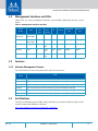
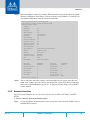
1.3 Management Interfaces and FRUs
Table 4 lists the various management interfaces and available replacement parts per system
model.
Table 4 - Management Interfaces and FRUs
System
Model
USB
MGT
Ports
Qty.
MGT
Ports
Location
I
2
C
Console
Replaceable
PSU
Replaceable
Fan
SX1012/
SX1012X
Front
(mini-USB)
1 Front Rear Front N/A N/A
SX1016 Front
(mini-USB)
1 Front N/A Front N/A N/A
SX1024 Rear 2 Front
Rear
Rear Front 2 FRUs 2 FRUs
SX1036 Front 2 Front
(x2)
Rear Front 2 FRUs 1 FRU
SX1400 Rear 2 Front
Rear
Rear Front 2 FRUs 2 FRUs
1.4 Features
1.4.1 Network Management Feature
For a full feature list, refer to the product brief of the relevant system:
System
Model
USB
SX1012 http://www.mellanox.com/related-docs/prod_eth_switches/PB_SX1012.pdf
SX1012X http://www.mellanox.com/related-do
cs/prod_eth_switches/PB_SX1012X.pdf
SX1016 http://www.mellanox.com/related-do
cs/prod_eth_switches/PB_SX1016.pdf
SX1024 http://www.mellanox.com/related-do
cs/prod_eth_switches/PB_SX1024.pdf
SX1036 http://www.mellanox.com/related-do
cs/prod_eth_switches/PB_SX1036.pdf
SX1400 http://www.mellanox.com/related-do
cs/prod_eth_switches/PB_SX1400.pdf
1.5 Certifications
The list of certifications (such as EMC, Safety and others) per system for different regions of the
world is located on the Mellanox website at:
http://www.mellanox.co
m/page/environmental_compliance

Rev 1.412 Mellanox Technologies
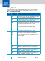
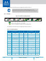
1.6 Ordering Information
the following table lists ordering information for the available systems. Please pay attention to
the airflow direction when ordering your system. For more details, see
“Air Flow” on page 18._
Table 5 - Ordering Part Numbers (OPNs)
System
Model
OPN Description
SX1012 MSX1012B-
1BFS
SwitchX®-2 based 40GbE, 1U Open Ethernet Switch with MLNX-OS,
12 QSFP+ ports, 1 Power Supply (AC), short depth, PPC460, Connector
airflow out, Rail Kit must be purchased separately, RoHS6
MSX1012B-
2BFS
SwitchX®-2 based 40GbE, 1U Open Ethernet Switch with MLNX-OS,
12 QSFP+ ports, 2 Power Supplies (AC), short depth, PPC460, Connector
airflow out, Rail Kit must be purchased separately, RoHS6
MSX1012B-
2BRS
SwitchX®-2 based 40GbE, 1U Open Ethernet Switch with MLNX-OS,
12 QSFP+ ports, 2 Power Supplies (AC), short depth, PPC460, Connector
airflow in, Rail Kit must be purchased separately, RoHS6
SX1012X SX1012X-2BFS SwitchX®-2 based, 1U Open Ethernet Switch with MLNX-OS, 12
QSFP+ ports, 2 Power Supplies (AC), short depth, PPC460, Connector
airflow out, Rail Kit must be purchased separately, RoHS6
SX1012X-2BRS SwitchX®-2 based, 1U Open Ethernet Switch with MLNX-OS, 12
QSFP+ ports, 2 Power Supplies (AC), short depth, PPC460, Connector
airflow in, Rail Kit must be purchased separately, RoHS6
SX1016 MSX1016X-
2BFR
SwitchX® based 64-port SFP+ 10GbE, 1U Ethernet switch. 2PS, Short
depth, PSU side to Connector side airflow, Rail kit and ROHS6
MSX1016X-
2BFS
SwitchX®-2 based 10GbE, 1U Open Ethernet Switch with MLNX-OS,
64 SFP+ ports, 2 Power Supplies (AC), Short depth, PPC460, C2P air
-
flow, Rail kit, RoHS6
MSX1016X-
2BRR
SwitchX® based 64-port SFP+ 10GbE. 1U Ethernet switch. 2PS, Short
depth, Connector side to PSU side airflow, Rail kit and ROHS6
MSX1016X-
2BRS
SwitchX®-2 based 10GbE, 1U Open Ethernet Switch with MLNX-OS,
64 SFP+ ports, 2 Power Supplies (AC), Short depth, PPC460, P2C air
-
flow, Rail kit, RoHS6
SX1024 MSX1024B-
1BFS
SwitchX®-2 based10GbE/40GbE, 1U Open Ethernet Switch with
MLNX-OS, 48 SFP+ ports, 12 QSFP+ ports, 1 Power Supply (AC),
PPC460, short depth, C2P airflow, Rail kit, RoHS6
MSX1024B-
1BRS
SwitchX®-2 based10GbE/40GbE, 1U Open Ethernet Switch with
MLNX-OS, 48 SFP+ ports, 12 QSFP+ ports, 1 Power Supply (AC),
PPC460, short depth, P2C airflow, Rail kit, RoHS6
MSX1024B-
2BFS
SwitchX®-2 based10GbE/40GbE, 1U Open Ethernet Switch with
MLNX-OS, 48 SFP+ ports, 12 QSFP+ ports, 2 Power Supplies (AC),
PPC460, short depth, C2P airflow, Rail kit, RoHS6
MSX1024B-
2BRS
SwitchX®-2 based10GbE/40GbE, 1U Open Ethernet Switch with
MLNX-OS, 48 SFP+ ports, 12 QSFP+ ports, 2 Power Supplies (AC),
PPC460, short depth, P2C airflow, Rail kit, RoHS6

Introduction to Mellanox SX10XX/SX1X00 Systems
Rev 1.4
13Mellanox Technologies
SX1400 MSX1400-BS2F2 SwitchX®-2 based 10GbE/40GbE, 1U Open Ethernet Switch with
MLNX-OS, 48 SFP+ ports, 12 QSFP+ ports, 2 Power Supplies (AC), x86
quad core, standard depth, C2P airflow, Rail kit, RoHS6
MSX1400-BS2R2 SwitchX®-2 based 10GbE/40GbE, 1U Open Ethernet Switch with
MLNX-OS, 48 SFP+ ports, 12 QSFP+ ports, 2 Power Supplies (AC), x86
quad core, standard depth, P2C airflow, Rail kit, RoHS6
SX1036 MSX1036B-
1BRR
SwitchX® based 36-port QSFP 40GbE 1U Ethernet Switch, 36 QSFP
ports, 1 PS, Short depth, Connector side to PSU side airflow, Rail Kit and
RoHS6
MSX1036B-
1BRS
SwitchX®-2 based 40GbE, 1U Open Ethernet Switch with MLNX-OS,
36 QSFP+ ports, 1 Power Supply (AC), PPC460, short depth, P2C air
-
flow, Rail Kit, RoHS6
MSX1036B-
1SFR
SwitchX® based 36-port QSFP 40GbE 1U Ethernet Switch, 36 QSFP
ports, 1 PS, Standard depth, PSU side to Connector side airflow, Rail Kit
and RoHS6
MSX1036B-1SFS SwitchX®-2 based 40GbE, 1U Open Ethernet Switch with MLNX-OS,
36 QSFP+ ports, 1 Power Supply (AC), PPC460, standard depth, C2P air
-
flow, Rail Kit, RoHS6
MSX1036B-
2BRS
SwitchX®-2 based 40GbE, 1U Open Ethernet Switch with MLNX-OS,
36 QSFP+ ports, 2 Power Supplies (AC), PPC460, short depth, P2C air
-
flow, Rail Kit, RoHS6
MSX1036B-2SFS SwitchX®-2 based 40GbE, 1U Open Ethernet Switch with MLNX-OS,
36 QSFP+ ports, 2 Power Supplies (AC), PPC460, standard depth, C2P
airflow, Rail Kit, RoHS6
Table 5 - Ordering Part Numbers (OPNs)
System
Model
OPN Description

Installation
Rev 1.4
17Mellanox Technologies
2 Installation
Installation and initialization of the system require attention to the normal mechanical, power,
and thermal precautions for rack-mounted equipment.
The installation procedure for the Metrox s
ystem involves the following phases:
1. Follow the safety warnings in Section E.2,“Installation Safety Warnin
gs (English),” on page
107.
2. Pay attention to the air flow consideration within the
system and rack - refer to “Air Flow” on
page 18.
3. Make sure that none of the package contents is missing or damaged - see “Package Contents”
on page 20
4. Mount the system to the rack - see “Mounting Options” on page 21.
5. Ground the system, refer to “Grounding” on page 33.
6. Power on the system - refer to “Initial Power On” on page 39
7. Perform system bring-up - see “System Bring-Up” on page 41
FRU replacements are described in Section 2.10 on page 46.
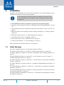
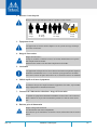
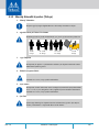
2.1 Safety Warnings
Prior to the installation, please review the safety warnings as follows:
For Nordic Countries Notices, see .Section E.1,“Nordic Countries Notices,” on page 107
For Safety Warnings in English, see Section E.2,“Installation Safety W
arnings (English),” on
page 107.
For Safety Warnings in Hebrew, see Section E.3, “(תירבע) הנקתהב תו
חיטב תורהזא,” on page 73.
For Safety Warnings
in Chinese, see page 113.
For Safety Warnings in French, see Section E.5, “Avertissements de sécurité pour l'installation
(French),” on page 116.
For Safety Warnings in German, Section E.6, “Installation Sicherheitshinweise(German),” on
page 120.
For Safety Warnings in Spanish,
see Section E.7, “Advertencias de seguridad de instalación
(Spanish),” on page 123.
For Safety Warnings in Russian, see Section E.8, “Пре
дупреждения по технике безопасности
при уст
ановке (Russian),” on page 126.
For Safety Warnings in Romanian, see Section E.9, “Avertismente privind siguranţa l
a instalare
(Romanian),” on page 129.
The rack mounting holes conform to the EIA-310 standard for 19-inch racks. Take
precautions to guarantee proper ventilation in order to maintain good airflow at ambi-
ent temperature.

Rev 1.418 Mellanox Technologies
For Safety Warnings in Croatian, see Section E.10, “Sigurnosna upozorenja za instaliranje (Croa-
tian),” on page 132.
For Safety Warnings in Italian, see Section E.11, “Avvertenze di sicurezza per l’installazione
(italiano),” on page 135.
For Safety Warnings in Turkish see Section E.12, “Montaj Güvenlik Uyarıları (Türk
çe),” on
page 139.
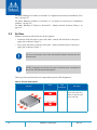
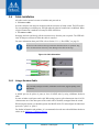
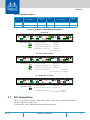
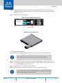
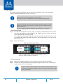
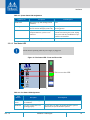
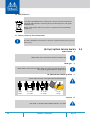
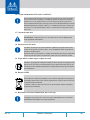
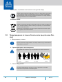
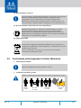
2.2 Air Flow
Mellanox systems are offered with two air flow patterns:
• Connector (front) side inlet to power side outlet -
marked with red labels on the power
supply side as shown in Figure 2.
• Power (rear) side inlet to connector side outlet
- marked with blue labels on the power
supply side as shown in Figure 3.
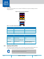
Table 6 provides an air flow label color legend and respective OPN designations,
All servers and systems in the same rack should be planned with the same air-
flow direction.
All FRU components need to have the same air flow direction. A mismatch in
the air flow will affect the heat dissipation.
Table 6 - Air Flow Label Legend
Direction
Label OPN
Designation
Description
R Connector side inlet to
power side outlet. Red
labels are placed on the
power inlet side.

Installation
Rev 1.4
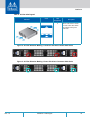
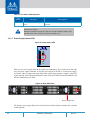
19Mellanox Technologies
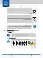
Figure 2: Air Flow Direction Marking - Connector Side Inlet to Power Side Outlet
Figure 3: Air Flow Direction Marking - Power Side Inlet to Connector Side Outlet
OK
!
!
OK
OK
!
!
OK
I2C
OK
!
!
OK
OK
!
!
OK
I2C
F Power side inlet to connec-
tor side outlet. Blue labels
are
placed on the power
inlet side.
Table 6 - Air Flow Label Legend
Direction
Label OPN
Designation
Description

Rev 1.420 Mellanox Technologies
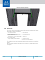
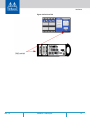
2.3 Package Contents
Before installing your new system, unpack the system, and check, against the parts list below,
that all the parts have been sent. Check the parts for visible damage that may have occurred
during shipping.
The system package content is as follows:
• 1 – System
• 1 – Rail kit (not applicable for half-width systems)
• 1 – Power cable for each power supply unit – Type C13-C14
• 1 – Harness: HAR000028 – Harness RS232 2M ca
ble – DB9 to RJ-45
• 1 – Quick Start Guide
The rear view shown in the above figures does not apply to SX1012/SX1012X,
SX1016 and SX1024.
If anything is damaged or missing, contact your sales representative at support@mella-
nox.com.

Installation
Rev 1.4
21Mellanox Technologies
2.4 Mounting Options
2.4.1 19” Systems Mounting
This section is applicable for 19” systems.
There are two installation kit optio
ns: standard and short. Standard depth systems should be
mounted using the standard rail kit; short systems can be mounted using either of the rail kits.
Table 7 - Installation Kit Options
Kit OPN Rack Size
MSX60-BKIT 40-60 cm deep (Short)
MSX60-SKIT 60-80 cm deep (Standard)
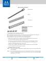
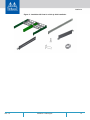
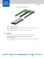
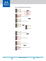
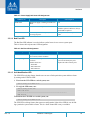
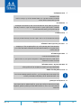
The following parts are included in the rail kit rack (see Figure 4):
• Two rails
• Two rail slides
• Two system slides
• 16 recessed flat head (6-32) screws (with extras)
• 10 caged nuts
• 10 pan head (M6) screw bolts

Rev 1.422 Mellanox Technologies
Figure 4: Rack Rail Kit Parts
System slide x2
Rail x2
Rail slide x2
Nuts and bolts
Screws
Planning the system’s placement in the rack
Before mounting the system to the rack, select the
way you wish to place the system. Pay atten-
tion to the airflow within the rack co
oling, connector and cabling options.
While planning how to place the system, review the following points:
• Make sure the system air flow is compatible with your installation selection. It is
import-
ant to keep the airflow within the rack in the
same direction.
• In case there are cables that cannot bend within
the rack or in case more space is needed
for cable bending radius, it is possible to recess the connector side or the FRU side by 2”
(5.08cm) by optional placement of the system’s rails.
• The FRU side is extractable. Mounting the sliding
rail inverted to the system will allow
you to slide the FRU side of the system, in and out.
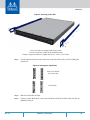
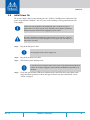
Mounting the slides to the system
Step 1. The recession feature is bi-directional, meaning that you can recess the system either back-
ward or forward.
Step 2. Screw the system slides onto the system. Use 5 flat head 6-32 screws for a short system and
7 screws for a standard depth system to connect each system slide. The recommended tight-
ening torque is 1.5±0.2 Nm.

Installation
Rev 1.4
23Mellanox Technologies
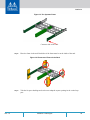
Figure 5: Screwing on the Rail
5 screws per side are needed for the short system.
7 screws per side are needed for the standard system.
If using a torque screwdriver to tighten the screws, set it to 1.5±0.2 Nm.
Step 3. Clip the caged nuts into the holes in the rack on the side of the rack you will be sliding the
system into.
Figure 6: Inserting the Caged Nuts
Side you will slide
the system into
Second side
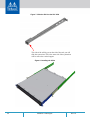
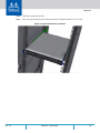
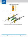
Step 4. Slide the rail into the rail slide.
Step 5. Using two of the M6 bolts for each corner, install the rails and rail slides in the rack. Do not
tighten the bolts yet.
Pagina se încarcă...
Pagina se încarcă...
Pagina se încarcă...
Pagina se încarcă...
Pagina se încarcă...
Pagina se încarcă...
Pagina se încarcă...
Pagina se încarcă...
Pagina se încarcă...
Pagina se încarcă...
Pagina se încarcă...
Pagina se încarcă...
Pagina se încarcă...
Pagina se încarcă...
Pagina se încarcă...
Pagina se încarcă...
Pagina se încarcă...
Pagina se încarcă...
Pagina se încarcă...
Pagina se încarcă...
Pagina se încarcă...
Pagina se încarcă...
Pagina se încarcă...
Pagina se încarcă...
Pagina se încarcă...
Pagina se încarcă...
Pagina se încarcă...
Pagina se încarcă...
Pagina se încarcă...
Pagina se încarcă...
Pagina se încarcă...
Pagina se încarcă...
Pagina se încarcă...
Pagina se încarcă...
Pagina se încarcă...
Pagina se încarcă...
Pagina se încarcă...
Pagina se încarcă...
Pagina se încarcă...
Pagina se încarcă...
Pagina se încarcă...
Pagina se încarcă...
Pagina se încarcă...
Pagina se încarcă...
Pagina se încarcă...
Pagina se încarcă...
Pagina se încarcă...
Pagina se încarcă...
Pagina se încarcă...
Pagina se încarcă...
Pagina se încarcă...
Pagina se încarcă...
Pagina se încarcă...
Pagina se încarcă...
Pagina se încarcă...
Pagina se încarcă...
Pagina se încarcă...
Pagina se încarcă...
Pagina se încarcă...
Pagina se încarcă...
Pagina se încarcă...
Pagina se încarcă...
Pagina se încarcă...
Pagina se încarcă...
Pagina se încarcă...
Pagina se încarcă...
Pagina se încarcă...
Pagina se încarcă...
Pagina se încarcă...
Pagina se încarcă...
Pagina se încarcă...
Pagina se încarcă...
Pagina se încarcă...
Pagina se încarcă...
Pagina se încarcă...
Pagina se încarcă...
Pagina se încarcă...
Pagina se încarcă...
Pagina se încarcă...
Pagina se încarcă...
Pagina se încarcă...
Pagina se încarcă...
Pagina se încarcă...
Pagina se încarcă...
Pagina se încarcă...
Pagina se încarcă...
Pagina se încarcă...
-
 1
1
-
 2
2
-
 3
3
-
 4
4
-
 5
5
-
 6
6
-
 7
7
-
 8
8
-
 9
9
-
 10
10
-
 11
11
-
 12
12
-
 13
13
-
 14
14
-
 15
15
-
 16
16
-
 17
17
-
 18
18
-
 19
19
-
 20
20
-
 21
21
-
 22
22
-
 23
23
-
 24
24
-
 25
25
-
 26
26
-
 27
27
-
 28
28
-
 29
29
-
 30
30
-
 31
31
-
 32
32
-
 33
33
-
 34
34
-
 35
35
-
 36
36
-
 37
37
-
 38
38
-
 39
39
-
 40
40
-
 41
41
-
 42
42
-
 43
43
-
 44
44
-
 45
45
-
 46
46
-
 47
47
-
 48
48
-
 49
49
-
 50
50
-
 51
51
-
 52
52
-
 53
53
-
 54
54
-
 55
55
-
 56
56
-
 57
57
-
 58
58
-
 59
59
-
 60
60
-
 61
61
-
 62
62
-
 63
63
-
 64
64
-
 65
65
-
 66
66
-
 67
67
-
 68
68
-
 69
69
-
 70
70
-
 71
71
-
 72
72
-
 73
73
-
 74
74
-
 75
75
-
 76
76
-
 77
77
-
 78
78
-
 79
79
-
 80
80
-
 81
81
-
 82
82
-
 83
83
-
 84
84
-
 85
85
-
 86
86
-
 87
87
-
 88
88
-
 89
89
-
 90
90
-
 91
91
-
 92
92
-
 93
93
-
 94
94
-
 95
95
-
 96
96
-
 97
97
-
 98
98
-
 99
99
-
 100
100
-
 101
101
-
 102
102
-
 103
103
-
 104
104
-
 105
105
-
 106
106
-
 107
107


Mellanox Technologies SX1012X Manual de utilizare
- Tip
- Manual de utilizare
în alte limbi
Lucrări înrudite
-
Mellanox Technologies MSX1024B-2BFS Manual de utilizare
-
-
-
Mellanox Technologies SX6025 Manual de utilizare
-
-
-
Mellanox Technologies MSX6036G-2SRS Manual de utilizare
-