Makita BTD129 Manual de utilizare
- Categorie
- Unelte electrice
- Tip
- Manual de utilizare

1
GB
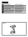
Cordless Impact Driver INSTRUCTION MANUAL
UA
PL
Akumulatorowy Wkrtak Udarowy INSTRUKCJA OBSUGI
RO
Main de înurubat cu impact cu acumulator
MANUAL DE INSTRUCIUNI
DE
Akku-Schlagschrauber BEDIENUNGSANLEITUNG
HU
Akkumulátoros ütvecsavarbehajtó HASZNÁLATI KÉZIKÖNYV
SK
Akumulátorový rázový uahova NÁVOD NA OBSLUHU
CZ
Akumulátorový rázový utahovák NÁVOD K OBSLUZE
BTD129

2
1
2
3
1 012781
1
2 012128
1
3 012782
1
4 012783
1
AB
5 012784 6 004521
1
2
7 011406
1
23
8 011407
1
2
3
9 012787
10 012788
1
11 012912

3
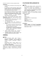
ENGLISH (Original instructions)
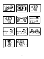
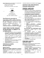
Explanation of general view
1-1. Red indicator
1-2. Button
1-3. Battery cartridge
2-1. Star marking
3-1. Switch trigger
4-1. Lamp
5-1. Reversing switch lever
7-1. Bit
7-2. Sleeve
8-1. Bit
8-2. Bit-piece
8-3. Sleeve
9-1. Groove
9-2. Hook
9-3. Screw
11-1. Vent
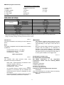
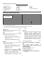
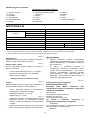
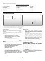
SPECIFICATIONS
Model BTD129
Machine screw 4 mm - 8 mm
Standard bolt 5 mm - 14 mm
Capacities
High tensile bolt 5 mm - 12 mm
No load speed (min
-1
) 0 - 2,500
Impacts per minute 0 - 3,200
Overall length 147 mm
Battery cartridge BL1815 BL1830
Net weight 1.3 kg 1.5 kg
Rated voltage D.C.18 V
• Due to our continuing program of research and development, the specifications herein are subject to change without notice.
• Specifications and battery cartridge may differ from country to country.
• Weight, with battery cartridge, according to EPTA-Procedure 01/2003
ENE033-1
Intended use
The tool is intended for screw driving in wood, metal and
plastic.
ENG905-1
Noise
The typical A-weighted noise level determined according
to EN60745:
Sound pressure level (L
pA
) : 94 dB(A)
Sound power level (L
WA
) : 105 dB(A)
Uncertainty (K) : 3 dB(A)
Wear ear protection
ENG900-1
Vibration
The vibration total value (tri-axial vector sum)
determined according to EN60745:
Work mode : impact tightening of fasteners of the
maximum capacity of the tool
Vibration emission (a
h
) : 15.0 m/s
2
Uncertainty (K) : 1.5 m/s
2
ENG901-1
•
The declared vibration emission value has been
measured in accordance with the standard test
method and may be used for comparing one tool
with another.
• The declared vibration emission value may also be
used in a preliminary assessment of exposure.
WARNING:
• The vibration emission during actual use of the
power tool can differ from the declared emission
value depending on the ways in which the tool is
used.
• Be sure to identify safety measures to protect the
operator that are based on an estimation of
exposure in the actual conditions of use (taking
account of all parts of the operating cycle such as
the times when the tool is switched off and when it
is running idle in addition to the trigger time).
ENH101-15
For European countries only
EC Declaration of Conformity
We Makita Corporation as the responsible
manufacturer declare that the following Makita
machine(s):
Designation of Machine:
Cordless Impact Driver
Model No./ Type: BTD129
are of series production and
Conforms to the following European Directives:
2006/42/EC
And are manufactured in accordance with the following
standards or standardised documents:
EN60745

4
The technical documentation is kept by our authorised
representative in Europe who is:
Makita International Europe Ltd.
Michigan Drive, Tongwell,
Milton Keynes, Bucks MK15 8JD, England
24.11.2011
000230
Tom oyasu Kat o
Director
Makita Corporation
3-11-8, Sumiyoshi-cho,
Anjo, Aichi, 446-8502, JAPAN
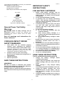
GEA010-1
General Power Tool Safety
Warnings
WARNING Read all safety warnings and all
instructions. Failure to follow the warnings and
instructions may result in electric shock, fire and/or
serious injury.
Save all warnings and instructions for
future reference.
GEB054-1
CORDLESS IMPACT DRIVER
SAFETY WARNINGS
1. Hold power tool by insulated gripping
surfaces, when performing an operation
where the fastener may contact hidden wiring.
Fasteners contacting a "live" wire may make
exposed metal parts of the power tool "live" and
could give the operator an electric shock.
2. Always be sure you have a firm footing.
Be sure no one is below when using the tool in
high locations.
3. Hold the tool firmly.
4. Wear ear protectors.
SAVE THESE INSTRUCTIONS.
WARNING:
DO NOT let comfort or familiarity with product
(gained from repeated use) replace strict adherence
to safety rules for the subject product.
MISUSE or failure to follow the safety rules stated in
this instruction manual may cause serious personal
injury.
ENC007-7
IMPORTANT SAFETY
INSTRUCTIONS
FOR BATTERY CARTRIDGE
1. Before using battery cartridge, read all
instructions and cautionary markings on (1)
battery charger, (2) battery, and (3) product
using battery.
2. Do not disassemble battery cartridge.
3. If operating time has become excessively
shorter, stop operating immediately. It may
result in a risk of overheating, possible burns
and even an explosion.
4. If electrolyte gets into your eyes, rinse them
out with clear water and seek medical
attention right away. It may result in loss of
your eyesight.
5. Do not short the battery cartridge:
(1) Do not touch the terminals with any
conductive material.
(2) Avoid storing battery cartridge in a
container with other metal objects such as
nails, coins, etc.
(3) Do not expose battery cartridge to water
or rain.
A battery short can cause a large current flow,
overheating, possible burns and even a
breakdown.
6. Do not store the tool and battery cartridge in
locations where the temperature may reach or
exceed 50 C (122 F).
7. Do not incinerate the battery cartridge even if
it is severely damaged or is completely worn
out. The battery cartridge can explode in a fire.
8. Be careful not to drop or strike battery.
9. Do not use a damaged battery.
SAVE THESE INSTRUCTIONS.
Tips for maintaining maximum battery life
1. Charge the battery cartridge before
completely discharged.
Always stop tool operation and charge the
battery cartridge when you notice less tool
power.
2. Never recharge a fully charged battery
cartridge.
Overcharging shortens the battery service life.
3. Charge the battery cartridge with room
temperature at 10 C - 40 C (50 F - 104 F).
Let a hot battery cartridge cool down before
charging it.
4. Charge the battery cartridge once in every six
months if you do not use it for a long period of
time.

5
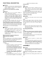
FUNCTIONAL DESCRIPTION
CAUTION:
• Always be sure that the tool is switched off and the
battery cartridge is removed before adjusting or
checking function on the tool.
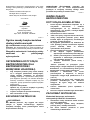
Installing or removing battery cartridge
Fig.1
CAUTION:
• Always switch off the tool before installing or
removing of the battery cartridge.
• Hold the tool and the battery cartridge firmly when
installing or removing battery cartridge. Failure to
hold the tool and the battery cartridge firmly may
cause them to slip off your hands and result in
damage to the tool and battery cartridge and a
personal injury.
To remov e t he b at te ry ca rt rid ge, s lide it f ro m th e t ool
while sliding the button on the front of the cartridge.
To i ns tall th e ba tter y c ar tr idge , ali gn th e t on gue on the
battery cartridge with the groove in the housing and slip
it into place. Insert it all the way until it locks in place with
a little click. If you can see the red indicator on the upper
side of the button, it is not locked completely.
CAUTION:
• Always install the battery cartridge fully until the
red indicator cannot be seen. If not, it may
accidentally fall out of the tool, causing injury to
you or someone around you.
• Do not install the battery cartridge forcibly. If the
cartridge does not slide in easily, it is not being
inserted correctly.
Battery protection system (Lithium-ion
battery with star marking)
Fig.2
Lithium-ion batteries with a star marking are equipped
with a protection system. This system automatically cuts
off power to the tool to extend battery life.
The tool will automatically stop during operation if the
tool and/or battery are placed under one of the following
conditions:
• Overloaded:
The tool is operated in a manner that causes
it to draw an abnormally high current.
In this situation, release the switch trigger on
the tool and stop the application that caused
the tool to become overloaded. Then pull the
switch trigger again to restart.
If the tool does not start, the battery is
overheated. In this situation, let the battery
cool before pulling the switch trigger again.
• Low battery voltage:
The remaining battery capacity is too low and
the tool will not operate. In this situation,
remove and recharge the battery.
Switch action
Fig.3
CAUTION:
• Before inserting the battery cartridge into the tool,
always check to see that the switch trigger
actuates properly and returns to the "OFF" position
when released.
To sta rt t he t ool , s impl y p ull the s wi tch t ri gger. To ol
speed is increased by increasing pressure on the switch
trigger. Release the switch trigger to stop.
Lighting up the lamp
CAUTION:
• Do not look in the light or see the source of light
directly.
Fig.4
Pull the switch trigger to light up the lamp. The lamp
keeps on lighting while the switch trigger is being pulled.
The lamp goes out just after the switch trigger is
released.
NOTE:
• Use a dry cloth to wipe the dirt off the lens of lamp.
Be careful not to scratch the lens of lamp, or it may
lower the illumination.
Reversing switch action
Fig.5
This tool has a reversing switch to change the direction
of rotation. Depress the reversing switch lever from the A
side for clockwise rotation or from the B side for
counterclockwise rotation.
When the reversing switch lever is in the neutral position,
the switch trigger cannot be pulled.
CAUTION:
• Always check the direction of rotation before
operation.
• Use the reversing switch only after the tool comes
to a complete stop. Changing the direction of
rotation before the tool stops may damage the tool.
• When not operating the tool, always set the
reversing switch lever to the neutral position.
ASSEMBLY
CAUTION:
• Always be sure that the tool is switched off and the
battery cartridge is removed before carrying out
any work on the tool.
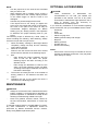
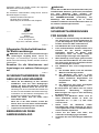
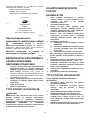
Installing or removing driver bit or socket bit
Fig.6
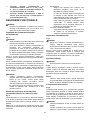
Use only bits that has inserting portion shown in the
figure.

6
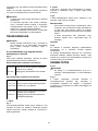
For tool with shallow bit hole
A=12mm
B=9mm
Use only these type of bit. Follow the
procedure (1).
(Note) Bit-piece is not necessary.
006348
For tool with deep bit hole
To ins ta ll th es e typ es o f b it s, fo ll ow
the procedure (1).
To ins ta ll th es e typ es o f b it s, fo ll ow
the procedure (2).
(Note) Bit-piece is necessary for
installing the bit.
A=17mm
B=14mm
A=12mm
B=9mm
011405
Procedure (1)
Fig.7
To i nsta ll th e bi t, pu ll the s le eve in t he d irec tion of the
arrow and insert the bit into the sleeve as far as it will go.
Then release the sleeve to secure the bit.
Procedure (2)
In addition to the procedure(1) above, insert the bit-piece
into the sleeve with its pointed end facing in.
Fig.8
To rem ove t he b it, p ull t he sl eeve in th e di rec ti on of th e
arrow and pull the bit out.
NOTE:
• If the bit is not inserted deep enough into the
sleeve, the sleeve will not return to its original
position and the bit will not be secured. In this case,
try re-inserting the bit according to the instructions
above.
• After inserting the bit, make sure that it is firmly
secured. If it comes out, do not use it.
Hook
Fig.9
The hook is convenient for temporarily hanging the tool.
This can be installed on either side of the tool.
To i ns ta ll t he ho ok, in se rt i t in to a groove i n th e too l
housing on either side and then secure it with a screw.
To re mo ve , loos en the sc re w an d th en ta ke i t out.
OPERATION
Fig.10
CAUTION:
• Do not cover vents, or it may cause overheating
and damage to the tool.
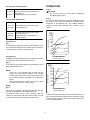
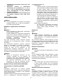
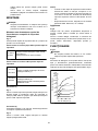
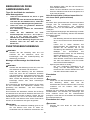
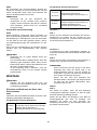
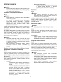
Fig.11
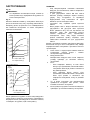
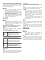
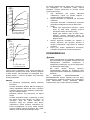
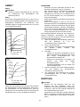
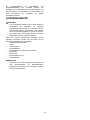
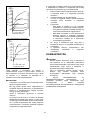
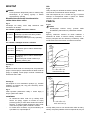
The proper fastening torque may differ depending upon
the kind or size of the screw/bolt, the material of the
workpiece to be fastened, etc. The relation between
fastening torque and fastening time is shown in the
figures.
120
100
80
60
40
20
0 1.0 2.0 3.0
M14
M12
M10
M8
(M14)
(M12)
(M10)
(M8)
Standard bolt
N m
Fastening torque
Fastening time (S)
Proper fastening torque
(kgf cm)
(1224)
(1020)
(816)
(612)
(408)
(204)
006255
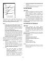
120
(1224)
100
(1020)
80
(816)
60
(612)
40
(408)
20
(204)
0 1.0 2.0 3.0
M12
M10
M8
(M12)
(M10)
(M8)
N m
Fastening torque
Fastening time (S)
Proper fastening torque
(kgf cm)
High tensile bolt
006257
Hold the tool firmly and place the point of the driver bit in
the screw head. Apply forward pressure to the tool to the
extent that the bit will not slip off the screw and turn the
tool on to start operation.

7
NOTE:
• Use the proper bit for the head of the screw/bolt
that you wish to use.
• When fastening M8 or smaller screw, choose a
proper impact force and carefully adjust pressure
on the switch trigger so that the screw is not
damaged.
• Hold the tool pointed straight at the screw.
• If the impact force is too strong you tighten the
screw for a time longer than shown in the figures,
the screw or the point of the driver bit may be
overstressed, stripped, damaged, etc. Before
starting your job, always perform a test operation
to determine the proper fastening time for your
screw.
The fastening torque is affected by a wide variety of
factors including the following. After fastening, always
check the torque with a torque wrench.
1. When the battery cartridge is discharged almost
completely, voltage will drop and the fastening
torque will be reduced.
2. Driver bit or socket bit
Failure to use the correct size driver bit or socket
bit will cause a reduction in the fastening torque.
3. Bolt
• Even though the torque coefficient and the
class of bolt are the same, the proper
fastening torque will differ according to the
diameter of bolt.
• Even though the diameters of bolts are the
same, the proper fastening torque will differ
according to the torque coefficient, the class of
bolt and the bolt length.
4. The manner of holding the tool or the material of
driving position to be fastened will affect the
torque.
5. Operating the tool at low speed will cause a
reduction in the fastening torque.
MAINTENANCE
CAUTION:
• Always be sure that the tool is switched off and the
battery cartridge is removed before attempting to
perform inspection or maintenance except for the
following troubleshooting related to the light.
• Never use gasoline, benzine, thinner, alcohol or
the like. Discoloration, deformation or cracks may
result.
To mai ntain pr od uc t SA FET Y an d RE LIABI LI TY, repa irs,
any other maintenance or adjustment should be
performed by Makita Authorized Service Centers,
always using Makita replacement parts.
OPTIONAL ACCESSORIES
CAUTION:
• These accessories or attachments are
recommended for use with your Makita tool
specified in this manual. The use of any other
accessories or attachments might present a risk of
injury to persons. Only use accessory or
attachment for its stated purpose.
If you need any assistance for more details regarding
these accessories, ask your local Makita Service Center.
• Screw bits
• Hook
• Socket bits
• Plastic carrying case
• Makita genuine battery and charger
• Bit-piece
• Battery protector
• Drill bits with1/4"
• Drill chuck assembly
NOTE:
• Some items in the list may be included in the tool
package as standard accessories. They may differ
from country to country.

8
( )
1-1.
1-2.
1-3.
2-1.
3-1.
4-1.
5-1.
7-1.
7-2.
8-1.
8-2.
8-3.
9-1.
9-2.
9-3.
11-1.
BTD129
4 - 8
5 - 14
5 - 12
(.
-1
) 0 - 2500
0 - 3200
147
BL1815 BL1830
1,3 1,5
18 .
• ' , ,
.
• .
• EPTA-Procedure 01/2003
ENE033-1
, .
ENG905-1
,
EN60745:
(L
pA
): 94 (A)
(L
WA
): 105 (A)
(K) : 3 (A)
ENG900-1
( )
EN60745:
:
(a
) : 15,0 /
2
(): 1,5 /
2
ENG901-1
•
.
•
.
:
•
.
•
,
(
, ,
).
ENH101-15
, Makita Corporation,
, ,
Makita:
:
/ : BTD129
:
2006/42/EC

9
:
EN60745
, :
Makita International Europe Ltd.
Michigan Drive, Tongwell,
Milton Keynes, Bucks MK15 8JD,
000230
Tom oyasu Kat o
Makita Corporation
3-11-8, Sumiyoshi-cho,
Anjo, Aichi, 446-8502,
GEA010-1
!
.
/ .
.
GEB054-1
1.
,
.
.
2. .
, .
3. .
4.
.
:
( );
.
, ,
.
ENC007-7
1.
,
(1)
, (2)
(3) ,
.
2. .
3. ,
.
,
.
4.
,
.
.
5. .
(1)
.
(2)
, ,
..
(3)
.
,
.
6.
,
50. C (122
F).
7.
,
.
.
8. .
9.
.
.
1.
, .

10
,
.
2.
.
.
3.
10 C - 40 C (50 F -
104 F).
.
4.
,
.
:
• ,
, ,
.
.
Fig.1
:
•
.
•
.
,
,
.
,
,
.
,
. ,
.
, ,
.
:
• ,
.
,
, .
•
. ,
, .
(-
)
Fig.2
-
.
.
, /
:
• :
.
,
.
, .
,
, .
,
.
• :
,
.
.
.
Fig.3
:
• ,
,
,
".", .
, ,
.
.
.
:
•
.
Fig.4
,
. ,
.
,
.

11
:
•
. ,
,
.
-.
Fig.5
.
-
"",
- "".
-
, .
:
•
.
•
.
.
• ,
-
.
:
• ,
, ,
, -
.
Fig.6
,
, .
A=12мм
B=9мм
Використовуйте тільки наконечник
цього типа. Виконайте процедуру (1).
(Примітка) Наконечник не потрібен
006348
Для встановлення свердел цього
типа слід виконати процедуру (1).
Для встановлення свердел цього
типа слід виконати процедуру (2).
(Примітка) Для встановлення
свердла потрібен наконечник.
A=17мм
B=14мм
A=12мм
B=9мм
011405
(1)
Fig.7
.
, .
(2)
(1), ,
,
.
Fig.8
, .
:
•
,
,
.
.
•
. ,
.
Fig.9
. -
.
, ,
-
. ,
, .

12
Fig.10
:
• ,
.
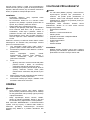
Fig.11
/,
, .
.
120
100
80
60
40
20
0 1,0 2,0 3,0
M14
M12
M10
M8
(M14)
(M12)
(M10)
(M8)
Стандартний болт
Н м
Момент затягування
Час закріплення (с)
Належний момент затягування
(кгс cм)
(1224)
(1020)
(816)
(612)
(408)
(204)
006255
120
(1224)
100
(1020)
80
(816)
60
(612)
40
(408)
20
(204)
0 1,0 2,0 3,0
M12
M10
M8
(M12)
(M10)
(M8)
Н м
Момент затягування
Час закріплення (с)
Належний момент затягування
(кгс cм)
Високоміцний болт
006257
. ,
, ,
, .
:
•
/,
.
• 8
, .
•
.
•
, ,
,
, ,
.
,
.
,
.
.
1.
,
.
2.
.
3.
•
,
.
•
,
,
.
4. ,
,
.
5.
.

13
:
• ,
,
,
, ' .
• , ,
, .
,
.
,
, ,
"",
"".
:
•
"",
.
.
.
,
"".
•
•
•
•
•
Makita
•
•
• 1/4"
•
:
•
.
.

14
POLSKI (Oryginalna instrukcja)
Objanienia do widoku ogólnego
1-1. Czerwony element
1-2. Przycisk
1-3. Akumulator
2-1. Znak gwiazdki
3-1. Spust przecznika
4-1. Lampka
5-1. Dwignia przecznika obrotów
wstecznych
7-1. Wierto
7-2. Tuleja
8-1. Wierto
8-2. Kocówka
8-3. Tuleja
9-1. Bruzda
9-2. Hak
9-3. ruba
11-1. Otwór wentylacyjny
SPECYFIAKCJE
Model BTD129
Wkrt do elementów metalowych
4 mm - 8 mm
ruba zwyka 5 mm - 14 mm
Wydajno
ruba o wysokiej wytrzymaoci
5 mm - 12 mm
Prdko bez obcienia (min
-1
) 0 - 2 500
Liczba udarów na minut 0 - 3 200
Dugo cakowita 147 mm
Akumulator BL1815 BL1830
Ciar netto 1,3 kg 1,5 kg
Napicie znamionowe Prd stay 18 V
• Ze wzgldu na stale prowadzone prace badawczo-rozwojowe, podane tu dane techniczne mog ulec zmianie bez powiadomienia.
• W innych krajach urzdzenie moe mie odmienne parametry techniczne I moe by wyposaone w inny akumulator.
• Waga urzdzenia wraz z akumulatorem obliczona zgodnie z procedur EPTA 01/2003
ENE033-1
Przeznaczenie
Narzdzie przeznaczone jest do osadzania wkrtów w
drewnie, metalu i tworzywach sztucznych.
ENG905-1
Poziom haasu i drga
Typowy równowany poziom dwiku A okrelony w
oparciu o EN60745:
Poziom cinienia akustycznego (L
pA
): 94 dB(A)
Poziom mocy akustycznejl (L
WA
): 105 dB(A)
Niepewno (K): 3 dB(A)
Naley stosowa ochraniacze na uszy
ENG900-1
Drgania
Cakowita warto poziomu drga (suma wektorów w 3
osiach) okrelona zgodnie z norm EN60745:
Praca : dokrcanie udarowe z wykorzystaniem
maksymalnych moliwoci narzdzia
Wytwarzanie drga (a
h
) : 15,0 m/s
2
Niepewno (K) : 1,5 m/s
2
ENG901-1
•
Deklarowana warto wytwarzanych drga zostaa
zmierzona zgodnie ze standardow metod
testow i mona j wykorzysta do porównywania
narzdzi.
• Deklarowan warto wytwarzanych drga mona
take wykorzysta we wstpnej ocenie naraenia.
OSTRZEENIE:
• Drgania wytwarzane podczas rzeczywistego
uytkowania elektronarzdzia mog si róni od
wartoci deklarowanej, w zalenoci od sposobu
jego uytkowania.
• W oparciu o szacowane naraenie w
rzeczywistych warunkach uytkowania naley
okreli rodki bezpieczestwa w celu ochrony
operatora (uwzgldniajc wszystkie elementy
cyklu dziaania, tj. czas, kiedy narzdzie jest
wyczone i kiedy pracuje na biegu jaowym, a
take czas, kiedy jest wczone).
ENH101-15
Dotyczy tylko krajów europejskich
Deklaracja zgodnoci UE
Niniejszym firma Makita Corporation jako
odpowiedzialny producent owiadcza, i opisywane
urzdzenie marki Makita:
Opis maszyny:
Akumulatorowy Wkrtak Udarowy
Model nr/ Typ: BTD129
jest produkowane seryjnie oraz
jest zgodne z wymogami okrelonymi w
nastpujcych dyrektywach europejskich:
2006/42/EC
Jest produkowane zgodnie z nastpujcymi normami
lub dokumentami normalizacyjnymi:
EN60745

15
Dokumentacja techniczna przechowywana jest przez
naszego autoryzowanego przedstawiciela na Europ,
którym jest:
Makita International Europe Ltd.
Michigan Drive, Tongwell,
Milton Keynes, Bucks MK15 8JD, Anglia
000230
Tom oyasu Kat o
Dyrektor
Makita Corporation
3-11-8, Sumiyoshi-cho,
Anjo, Aichi, 446-8502, JAPONIA
GEA010-1
Ogólne zasady bezpieczestwa
obsugi elektronarzdzi
OSTRZEENIE Przeczytaj wszystkie ostrzeenia i
instrukcje.
Nie przestrzeganie ich moe prowadzi do
porae prdem, poarów i/lub powanych obrae ciaa.
Wszystkie ostrzeenia i instrukcje naley
zachowa do póniejszego
wykorzystania.
GEB054-1
OSTRZEENIA DOTYCZCE
BEZPIECZESTWA (DLA
BEZPRZEWODOWEJ
WKRTARKI UDAROWEJ)
1. Gdy narzdzie podczas pracy moe zetkn
si z ukrytymi przewodami elektrycznymi,
naley trzyma urzdzenie za izolowane
uchwyty. Zetknicie z przewodem elektrycznym
pod napiciem powoduje, e równie odsonite
elementy metalowe narzdzia znajd si pod
napiciem, groc poraeniem operatora prdem
elektrycznym.
2. Zapewni stae podoe.
Upewni si, czy nikt nie znajduje si poniej
miejsca pracy na wysokoci.
3. Trzyma narzdzie w sposób niezawodny.
4. No ochraniacze na uszy.
ZACHOWA INSTRUKCJE.
OSTRZEENIE:
NIE WOLNO pozwoli, aby wygoda lub rutyna
(nabyta w wyniku wielokrotnego uywania
narzdzia) zastpiy cise przestrzeganie zasad
bezpieczestwa obsugi.
NIEWACIWE UYTKOWANIE narzdzia lub
niestosowanie si do zasad bezpieczestwa
podanych w niniejszej instrukcji obsugi moe
prowadzi do powanych obrae ciaa.
ENC007-7
WANE ZASADY
BEZPIECZESTWA
DOTYCZCE AKUMULATORA
1. Przed uyciem akumulatora zapozna si z
wszystkimi zaleceniami i znakami
ostrzegawczymi na (1) adowarce, (2)
akumulatorze i (3) wyrobie, w którym bdzie
uywany akumulator.
2. Akumulatora nie wolno rozbiera.
3. Jeeli czas pracy uleg znacznemu skróceniu,
naley natychmiast przerwa prac. Moe
bowiem doj do przegrzania, ewentualnych
poparze, a nawet eksplozji.
4. W przypadku przedostania si elektrolitu do
oczu, przemy je wod i niezwocznie uzyska
pomoc lekarsk. Moe on bowiem
spowodowa utrat wzroku.
5. Nie doprowadza do zwarcia akumulatora:
(1)
Nie dotyka styków przedmiotami
wykonanymi z materiaów przewodzcych.
(2) Unika przechowywania akumulatora w
pojemniku z metalowymi przedmiotami,
typu gwodzie, monety itp.
(3) Chroni akumulator przed wod i
deszczem.
Zwarcie prowadzi do przepywu prdu
elektrycznego o duym nateniu i przegrzania
akumulatora, co w konsekwencji moe grozi
poparzeniami a nawet awari urzdzenia.
6. Narzdzia i akumulatora nie wolno
przechowywa w miejscach, w których
temperatura osiga bd przekracza 50 C
(122 F).
7. Akumulatorów nie wolno pali, równie tych
powanie uszkodzonych lub cakowicie
zuytych. W ogniu mog one bowiem
eksplodowa.
8. Chroni akumulator przed upadkiem i
uderzeniami.
9.
Nie wolno uywa uszkodzonego akumulatora.
ZACHOWA INSTRUKCJE.
Wskazówki dotyczce zachowania
maksymalnej trwaoci akumulatora
1. Akumulator naley naadowa zanim zostanie
do koca rozadowany.
Gdy zauwaysz spadek mocy narzdzia,
przerwij prac i naaduj akumulator.
2. Nie wolno adowa powtórnie w peni
naadowanego akumulatora.

16
Przeadowanie akumulatora skraca jego czas
eksploatacji.
3. Akumulator adowa w temperaturze
mieszczcej si w przedziale 10 C - 40 C
(50 F - 104 F). Gdy akumulator jest gorcy,
przed przystpieniem do jego adowania
odczeka, a ostygnie.
4. aduj akumulator raz na sze miesicy, jeli
nie uywasz urzdzenia przez dugi okres
czasu.
OPIS DZIAANIA
UWAGA:
• Przed przystpieniem do regulacji lub przegldu
narzdzia upewni si, czy jest ono wyczone i
czy zosta wyjty akumulator.
Wkadanie i wyjmowanie akumulatora
Rys.1
UWAGA:
• Przed montaem lub demontaem akumulatora
naley wycza narzdzie
• Podczas wkadania lub wyjmowania akumulatora
naley mocno trzyma narzdzie i akumulator. W
przeciwnym razie mog one wylizgn si z rk,
powodujc uszkodzenie narzdzia lub
akumulatora i obraenia ciaa.
Aby wyj akumulator, naley przesun przycisk
znajdujcy si w przedniej jego czci i wysun
akumulator.
Aby zamontowa akumulator, wystarczy wyrówna
wystp na akumulatorze z rowkiem w obudowie i
wsun go na swoje miejsce. Akumulator naley
wsuwa do oporu, a si zablokuje, co jest
sygnalizowane delikatnym klikniciem. Jeli jest
widoczny czerwony wskanik w górnej czci przycisku,
akumulator nie zosta cakowicie zablokowany.
UWAGA:
• Naley go zamontowa cakowicie, tak aby
czerwony wskanik nie by widoczny. W
przeciwnym razie moe przypadkowo wypa z
urzdzenia, ranic operatora lub osoby postronne.
• Nie montowa akumulatora na si. Jeli
akumulator nie daje si swobodnie wsun,
prawdopodobnie zosta woony nieprawidowo.
System ochrony akumulatora (akumulator
litowo-jonowy ze znakiem gwiazdki)
Rys.2
Akumulatory litowo-jonowe ze znakiem gwiazdki
posiadaj w system ochrony. System ten automatycznie
odcina dopyw prdu do narzdzia w celu wyduenia
ywotnoci akumulatora.
Narzdzie zostanie automatycznie zatrzymane podczas
pracy w nastpujcych sytuacjach zwizanych z
narzdziem/akumulatorem:
• Przecienie:
Narzdzie pracuje w sposób przyczyniajcy
si do niezwykle wysokiego wzrostu napicia.
W takiej sytuacji naley zwolni jzyk
spustowy przecznika narzdzia i zatrzyma
wykonywan prac, która doprowadzia do
przecienia narzdzia. Nastpnie ponownie
pocign jzyk spustowy przecznika w
celu ponownego uruchomienia narzdzia.
Jeeli narzdzie nie wczy si, akumulator
uleg przegrzaniu. W takiej sytuacji naley
poczeka, a akumulator ostygnie przed
ponownym pocigniciem za jzyk spustowy
przecznika.
• Niskie napicie akumulatora:
Za niski poziom naadowania akumulatora,
aby narzdzie mogo pracowa. W takiej
sytuacji naley wyj akumulator i go
naadowa.
Wczanie
Rys.3
UWAGA:
• Przed woeniem akumulatora do narzdzia
zawsze sprawd, czy jzyk spustowy wycznika
dziaa prawidowo i po zwolnieniu powraca do
pooenia „OFF".
Aby uruchomi narzdzie, naley pocign za jzyk
spustowy przecznika. Prdko narzdzia ronie wraz
ze zwikszaniem nacisku na jzyk spustowy. W celu
zatrzymania urzdzenia wystarczy zwolni jzyk
spustowy przecznika.
Wczanie owietlenia
UWAGA:
• Nie patrze na wiato ani bezporednio na ródo
wiata.
Rys.4
W celu zapalenia lampki naley pocign za jzyk
spustowy. Lampka wieci dopóki jzyk spustowy
przecznika jest naciskany. Lampka ganie od razu po
zwolnieniu jzyka spustowego.
UWAGA:
• Uy suchej tkaniny aby zetrze zanieczyszczenia
z osony lampki. Uwaa, aby nie zarysowa
osony lampki, gdy moe to zmniejszy natenie
owietlenia.
Wczanie obrotów wstecznych.
Rys.5
Omawiane narzdzie jest wyposaone w przecznik
umoliwiajcy zmian kierunku obrotów. W celu
uzyskania obrotów zgodnych z ruchem wskazówek
zegara naley nacisn dwigni przecznika zmiany
kierunku obrotów po stronie A, natomiast by uzyska

17
obroty przeciwne do ruchu wskazówek zegara,
wystarczy nacisn dwigni przecznika po stronie B.
Gdy dwignia przecznika zmiany kierunku obrotów
znajduje si w pooeniu neutralnym, jzyk spustowy
przecznika jest zablokowany.
UWAGA:
• Przed uruchomieniem narzdzia naley zawsze
sprawdzi ustawienie kierunku obrotów.
• Kierunek obrotów mona zmienia tylko wówczas,
gdy urzdzenie cakowicie si zatrzyma. Zmiana
kierunku obrotów przed zatrzymaniem si
narzdzia grozi jego uszkodzeniem.
• Gdy narzdzie nie bdzie uywane, naley zawsze
ustawi dwigni przecznika zmiany kierunku
obrotów w pooeniu neutralnym.
MONTA
UWAGA:
• Przed przystpieniem do jakichkolwiek czynnoci
zwizanych z obsug narzdzia naley koniecznie
upewni si, czy jest ono wyczone i czy
akumulator zosta wyjty.
Monta i demonta tradycyjnej kocówki do
wkrcania lub kocówki nasadowej
Rys.6
Naley uywa wycznie kocówek posiadajcych
trzonki takie jak na rysunku.
Do narzdzia z pytkim otworem kocówki
A=12mm
B=9mm
Używaj końcówek tylko tego typu.
Postępuj zgodnie z procedurą (1).
(Uwaga) Adapter końcówki nie jest
wymagany.
006348
Do narzdzia z gbokim otworem kocówki
Aby montować końcówki tych typów
postępuj zgodnie z procedurą (1).
Aby montować końcówki tego typu,
postępuj zgodnie z procedurą (2).
(Uwaga) Adapter końcówki jest
wymagany do zamontowania tej końcówki.
A=17mm
B=14mm
A=12mm
B=9mm
011405
Procedura (1)
Rys.7
Aby zainstalowa kocówk pocignij za tulej w kierunku
strzaki i wsu kocówk jak najgbiej do tulei. Nastpnie
zwolnij tulej, aby zamocowa w niej kocówk.
Procedura (2)
Poza procedur (1) opisan powyej, naley wsun
kocówk do tulei ostrym kocem do wewntrz.
Rys.8
Aby wyj kocówk, pocignij tulej w kierunku strzaki
i zdecydowanym ruchem wycignij z niej kocówk.
UWAGA:
• Jeeli kocówka nie bdzie wsadzona
wystarczajco gboko do tulei, tuleja nie wróci do
swojego pierwotnego pooenia i kocówka nie
bdzie dobrze zamocowana. W takim przypadku
spróbuj ponownie woy kocówk zgodnie z
powyszymi instrukcjami.
• Po wsuniciu kocówki, naley sprawdzi, czy
trzyma si silnie w uchwycie. Jeli si wysuwa, nie
naley jej uywa.
Hak
Rys.9
Zaczep jest wygodny, aby na chwil zawiesi narzdzie.
Mona go zamontowa z jednej lub z drugiej strony
narzdzia.
Aby zamontowa zaczep, wsu go w rowek w obudowie
znajdujcy si z obu stron, a nastpnie przykr go
wkrtem. Aby zdemontowa zaczep, poluzuj wkrt i
cignij zaczep.
DZIAANIE
Rys.10
UWAGA:
• Nie zasania otworów wentylacyjnych. W
przeciwnym wypadku moe to doprowadzi do
przegrzania lub uszkodzenia narzdzia.
Rys.11
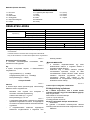
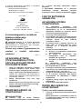
Odpowiedni moment dokrcania zaley od rodzaju i
wielkoci wkrtu/ruby, materiau, z jakiego wykonany
jest wkrcany element, itp. Zaleno momentu
dokrcania i czasu dokrcania pokazano na rysunkach.

18
120
100
80
60
40
20
0 1,0 2,0 3,0
M14
M12
M10
M8
(M14)
(M12)
(M10)
(M8)
Śruba zwykła
N m
Moment dokręcania
Czas dokręcania (S)
Właściwy moment dokręcania
(kgf cm)
(1224)
(1020)
(816)
(612)
(408)
(204)
006255
120
(1224)
100
(1020)
80
(816)
60
(612)
40
(408)
20
(204)
0 1,0 2,0 3,0
M12
M10
M8
(M12)
(M10)
(M8)
N m
Moment dokręcania
Czas dokręcania (S)
Właściwy moment dokręcania
(kgf cm)
Śruba o wysokiej wytrzymałości
006257
Trzymaj mocno narzdzie i wsu ostrze kocówki do
wkrcania do gniazda w bie wkrtu. Docinij narzdzie
w takim stopniu, aby kocówka nie wylizgna si z
gniazda wkrtu, i uruchom narzdzie, aby rozpocz
operacj wkrcania.
UWAGA:
• Do wybranego wkrtu/ruby dobierz waciw
kocówk.
• Podczas wkrcania wkrtów M8 lub mniejszych,
naley odpowiednio dobra si udaru i ostronie
wywiera nacisk na jzyk spustowy przecznika,
aby nie uszkodzi wkrtu.
• Narzdzie powinno by skierowane na wprost
wkrtu.
• Podczas wkrcania wkrtu z ustawion za du
si udaru przez czas duszy ni podany na
rysunkach, wkrt lub ostrze kocówki do
wkrcania mog by poddane zbyt duym
napreniom, zosta zerwane, uszkodzone itp.
Przed przystpieniem do pracy naley zawsze
wykona próbn operacj wkrcania, aby ustali
waciwy czas wkrcania dla danego wkrtu.
Na moment dokrcania ma wpyw wiele czynników, w
tym nastpujce. Po dokrceniu naley zawsze
sprawdzi moment dokrcenia za pomoc klucza
dynamometrycznego.
1. Gdy akumulator jest prawie cakowicie
rozadowany, pojawi si spadek napicia i
moment dokrcania zmniejszy si.
2. Zwyk
a kocówka do wkrcania lub kocówka
nasadowa
Stosowanie kocówki o niewaciwym rozmiarze
spowoduje zmniejszenie momentu dokrcania.
3. ruba
• Nawet jeli wspóczynnik momentu i klasa
ruby s takie same, waciwy moment
dokrcania zaley od rednicy ruby.
• Nawet jeli rednice rub s takie same,
waciwy moment dokrcania zaley od
wspóczynnika momentu, klasy ruby oraz od
dugoci ruby.
4. Sposób trzymania narzdzia lub materia, z
którego wykonany jest skrcany element w
miejscu przykrcania, maj wpyw na wielko
momentu.
5. Praca przy niskich prdkociach obrotowych
powoduje zmniejszenie momentu dokrcania.
KONSERWACJA
UWAGA:
• Przed przystpieniem do przegldu narzdzia lub
jego konserwacji (za wyjtkiem omówionych niej
rozwizywania problemów zwizanych z
owietleniem) upewnij si, czy jest ono wyczone i
czy akumulator zosta wyjty.
• Nie wolno uywa benzyny, benzenu,
rozpuszczalnika, alkoholu itp. Substancje takie
mog spowodowa odbarwienia, odksztacenia lub
pknicia.
Dla zachowania BEZPIECZESTWA i
NIEZAWODNOCI wyrobu, naprawy oraz inne prace
konserwacyjne i regulacyjne powinny by wykonywane
przez Autoryzowane Centra Serwisowe Makita,
wycznie przy uyciu czci zamiennych Makita.

19
AKCESORIA OPCJONALNE
UWAGA:
• Zaleca si stosowanie wymienionych akcesoriów i
dodatków razem z elektronarzdziem Makita
opisanym w niniejszej instrukcji. Stosowanie
jakichkolwiek innych akcesoriów i dodatków moe
stanowi ryzyko uszkodzenia ciaa. Stosowa
akcesoria i dodatki w celach wycznie zgodnych z
ich przeznaczeniem.
W razie potrzeby, wszelkiej pomocy i szczegóowych
informacji na temat niniejszych akcesoriów udziel
Pastwu lokalne Centra Serwisowe Makita.
• Kocówki do wkrtów
• Hak
• Kocówki
• Walizka z tworzywa sztucznego
• Oryginalny akumulator i adowarka firmy Makita
• Kocówka
• Zabezpieczenie akumulatora
• Kocówki wierta 1/4”
• Uchwyt wiertarski
UWAGA:
• Niektóre pozycje znajdujce si na licie mog by
doczone do pakietu narzdziowego jako
akcesoria standardowe. Mog to by róne
pozycje, w zalenoci od kraju.

20
ROMÂN (Instruciuni originale)
Explicitarea vederii de ansamblu
1-1. Indicator rou
1-2. Buton
1-3. Cartuul acumulatorului
2-1. Marcaj în stea
3-1. Trgaciul întreruptorului
4-1. Lamp
5-1. Levier de inversor
7-1. Scul
7-2. Manon
8-1. Scul
8-2. Portscul
8-3. Manon
9-1. Canelur
9-2. Agtoare
9-3. urub
11-1. Fant
SPECIFICAII
Model BTD129
urub cu cap 4 mm - 8 mm
Bulon standard 5 mm - 14 mm
Capaciti
Bulon de mare rezisten la traciune
5 mm - 12 mm
Turaia în gol (min
-1
) 0 - 2.500
Bti pe minut 0 - 3.200
Lungime total 147 mm
Cartuul acumulatorului BL1815 BL1830
Greutate net 1,3 kg 1,5 kg
Ten siune nomina l 18 V cc.
• Datorit programului nostru continuu de cercetare i dezvoltare, specificaiile din prezentul document pot fi modificate fr o
notificare prealabil.
• Specificaiile i ansamblul baterie pot diferi de la ar la ar.
• Greutatea, cu ansamblul baterie, conform procedurii EPTA 01/2003
ENE033-1
Destinaia de utilizare
Maina este destinat înurubrii în lemn, metal i
plastic.
ENG905-1
Emisie de zgomot
Nivelul de zgomot normal ponderat A determinat în
conformitate cu EN60745:
Nivel de presiune acustic (L
pA
): 94 dB(A)
Nivel putere sonor (L
WA
): 105 dB(A)
Eroare (K): 3 dB(A)
Purtai mijloace de protecie a auzului
ENG900-1
Vibraii
Valoarea total a vibraiilor (suma vectorilor tri-axiali)
determinat conform EN60745:
Mod de funcionare: strângerea cu oc a
elementelor de îmbinare la capacitatea maxim a
uneltei
Emisia de vibraii (a
h
): 15,0 m/s
2
Incertitudine (K): 1,5 m/s
2
ENG901-1
•
Nivelul de vibraii declarat a fost msurat în
conformitate cu metoda de test standard i poate fi
utilizat pentru compararea unei unelte cu alta.
• Nivelul de vibraii declarat poate fi, de asemenea,
utilizat într-o evaluare preliminar a expunerii.
AVERTISMENT:
• Nivelul de vibraii în timpul utilizrii reale a uneltei
electrice poate diferi de valoarea nivelului declarat,
în funcie de modul în care unealta este utilizat.
• Asigurai-v c identificai msurile de siguran
pentru a proteja operatorul, acestea fiind bazate pe
o estimare a expunerii în condiii reale de utilizare
(luând în considerare toate prile ciclului de
operare, precum timpii în care unealta a fost oprit,
sau a funcionat în gol, pe lâng timpul de
declanare).
ENH101-15
Numai pentru rile europene
Declaraie de conformitate CE
Noi, Makita Corporation ca productor responsabil,
declarm c urmtorul(oarele) utilaj(e):
Destinaia utilajului:
Main de înurubat cu impact cu acumulator
Modelul nr. / Tipul: BTD129
este în producie de serie i
Este în conformitate cu urmtoarele directive
europene:
2006/42/EC
i este fabricat în conformitate cu urmtoarele
standarde sau documente standardizate:
EN60745
Pagina se încarcă ...
Pagina se încarcă ...
Pagina se încarcă ...
Pagina se încarcă ...
Pagina se încarcă ...
Pagina se încarcă ...
Pagina se încarcă ...
Pagina se încarcă ...
Pagina se încarcă ...
Pagina se încarcă ...
Pagina se încarcă ...
Pagina se încarcă ...
Pagina se încarcă ...
Pagina se încarcă ...
Pagina se încarcă ...
Pagina se încarcă ...
Pagina se încarcă ...
Pagina se încarcă ...
Pagina se încarcă ...
Pagina se încarcă ...
Pagina se încarcă ...
Pagina se încarcă ...
Pagina se încarcă ...
Pagina se încarcă ...
Pagina se încarcă ...
Pagina se încarcă ...
Pagina se încarcă ...
Pagina se încarcă ...
-
 1
1
-
 2
2
-
 3
3
-
 4
4
-
 5
5
-
 6
6
-
 7
7
-
 8
8
-
 9
9
-
 10
10
-
 11
11
-
 12
12
-
 13
13
-
 14
14
-
 15
15
-
 16
16
-
 17
17
-
 18
18
-
 19
19
-
 20
20
-
 21
21
-
 22
22
-
 23
23
-
 24
24
-
 25
25
-
 26
26
-
 27
27
-
 28
28
-
 29
29
-
 30
30
-
 31
31
-
 32
32
-
 33
33
-
 34
34
-
 35
35
-
 36
36
-
 37
37
-
 38
38
-
 39
39
-
 40
40
-
 41
41
-
 42
42
-
 43
43
-
 44
44
-
 45
45
-
 46
46
-
 47
47
-
 48
48


Makita BTD129 Manual de utilizare
- Categorie
- Unelte electrice
- Tip
- Manual de utilizare
în alte limbi
- slovenčina: Makita BTD129 Používateľská príručka
- polski: Makita BTD129 Instrukcja obsługi
- Deutsch: Makita BTD129 Benutzerhandbuch
Lucrări conexe
-
Makita DTD155 Manual de utilizare
-
Makita BTD200 Manual de utilizare
-
-
-
-
-
-
-
-
Alte documente
-
Ferm CDM1101 Manualul proprietarului
-
-
-
-
-
Maktec MT690 Manual de utilizare
-
Milwaukee M12 ONEFTR12 Original Instructions Manual
-
 JBM 52076 Manualul utilizatorului
