Eaton DL1-34061 Series Instruction Leaflet
- Tip
- Instruction Leaflet

Emergency On Call Service: Local representative (www.eaton.eu/aftersales) or +49 (0)180 5223822 (de, en) 1/12
07/16 IL04020013Z
Instruction Leaflet
Montageanweisung
Notice d’installation
Instrucciones de montaje
Istruzioni per il montaggio
安安装装说说明明
Инструкция по монтажу
Montagehandleiding
Montagevejledning
Οδηγίες εγκατάστασης
Instruções de montagem
Monteringsanvisning
Asennusohje
Návod k montáži
Paigaldusjuhend
Szerelési utasítás
Montāžas instrukcija
Montavimo instrukcija
Instrukcja montażu
Navodila za montažo
Návod na montáž
Монтажни инструкции
Instrucţiuni de montaj
Upute za montažu
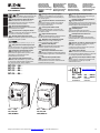
Electric current! Danger to life!
Only skilled or instructed persons may
carry out the following operations.
Lebensgefahr durch elektrischen Strom!
Nur Elektrofachkräfte und elektrotechnisch
unterwiesene Personen dürfen die im Folgenden
beschriebenen Arbeiten ausführen.
Tension électrique dangereuse !
Seules les personnes qualifiées et averties doivent
exécuter les travaux ci-après.
¡Corriente eléctrica! ¡Peligro de muerte!
El trabajo a continuación descrito debe ser realizado
por personas cualificadas y advertidas.
Tensione elettrica: Pericolo di morte!
Solo persone abilitate equalificatepossono eseguire
le operazioni di seguito riportate.
触触电电危危险险!!
只允许专业人员和受过专业训练的人员进行下列工作。
Электрический ток! Опасно для жизни!
Только специалисты или проинструктированные
лица могут выполнять следующие операции.
Levensgevaar door elektrische stroom!
Uitsluitend deskundigen in elektriciteit en
elektrotechnisch geïnstrueerde personen is het
toegestaan, de navolgend beschreven
werkzaamheden uit te voeren.
Livsfare på grund af elektrisk strøm!
Kun uddannede el-installatører og personer der
e instruerede i elektrotekniske arbejdsopgaver,
må udføre de nedenfor anførte arbejder.
en
de
fr
es
it
zh
ru
nl
da
Προσοχή, κίνδυνος ηλεκτροπληξίας!
Οι εργασίες που αναφέρονται στη συνέχεια θα
πρέπει να εκτελούνται μόνο από ηλεκτρολόγους
και ηλεκτροτεχνίτες.
Perigo de vida devido a corrente eléctrica!
Apenas electricistas e pessoas com formação
electrotécnica podem executar os trabalhos
que a seguir se descrevem.
Livsfara genom elektrisk ström!
Endast utbildade elektriker och personer som
undervisats i elektroteknik får utföra de arbeten
som beskrivs nedan.
Hengenvaarallinen jännite!
Vain pätevät sähköasentajat ja opastusta saaneet
henkilöt saavat suorittaa seuraavat työt.
Nebezpečí úrazu elektrickým proudem!
Níže uvedené práce smějí provádět pouze
osoby s elektrotechnickým vzděláním.
Eluohtlik! Elektrilöögioht!
Järgnevalt kirjeldatud töid tohib teostada ainult
elektriala spetsialist vői elektrotehnilise
instrueerimise läbinud personal.
Életveszély az elektromos áram révén!
Csak elektromos szakemberek és elektrotechnikában
képzett személyek végezhetik el a következőkben leírt
munkákat.
Elektriskā strāva apdraud dzīvību!
Tālāk aprakstītos darbus drīkst veikt tikai
elektrospeciālisti un darbam ar elektrotehniskām
iekārtām instruētās personas!
el
pt
sv
fi
cs
et
hu
lv
Pavojus gyvybei dėl elektros srovės!
Tik elektrikai ir elektrotechnikos specialistai gali
atlikti žemiau aprašytus darbus.
Porażenie prądem elektrycznym stanowi
zagrożenie dla życia!
Opisane poniżej prace mogą przeprowadzać tylko
wykwalifikowani elektrycy oraz osoby odpowiednio
poinstruowane w zakresie elektrotechniki.
Življenjska nevarnost zaradi
električnega toka!
Spodaj opisana dela smejo izvajati samo
elektrostrokovnjaki in elektrotehnično poučene osebe.
Nebezpečenstvo ohrozenia života
elektrickým prúdom!
Práce, ktoré sú nižšie opísané, smú vykonávat’
iba elektroodborníci a osoby s elektrotechnickým
vzdelaním.
Опасност за живота от електрически ток!
Операциите, описани в следващите раздели,
могат да се извършват само от
специалисти-електротехници и инструктиран
електротехнически персонал.
Atenţie! Pericol electric!
Toate lucrările descrise trebuie efectuate numai
de personal de specialitate calificat şi de persoane
cu cunoştiinţe profunde în electrotehnică.
Opasnost po život uslijed električne struje!
Radove opisane u nastavku smiju obavljati samo
stručni električari i osobe koje su prošle
elektrotehničku obuku.
lt
pl
sl
sk
bg
ro
hr
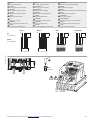
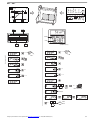
DC1-1D…-A6…
DC1-12…-A6…
DC1-32…-A6…
DC1-34…-A6…
DC1-…-A6S…
FS1, FS2, FS3
IP66, NEMA 4x
DC1-…-A66…
FS1, FS2, FS3
IP66, NEMA 4x
www.eaton.eu/powerxl
DC1-…-A6SN
DC1-…-A66N
MN04020003Z…
MN04020003Z…
DC1-…-A6SCE1
DC1-…-A66CE1
MN040022…
MN040023…
a
PWR
OFF
ON
REV
FWD
0

2/12Emergency On Call Service: Local representative (www.eaton.eu/aftersales) or +49(0) 1805223822 (de, en)
07/16 IL04020013Z
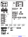
[mm (in)]
Mains (TN, TT)
TN-S TN-C TT
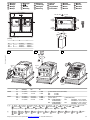
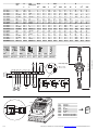
Dimensions and weights
Abmessungen und Gewichte
Encombrements et poids
Dimensiones y pesos
Dimensioni e pesi
尺尺寸寸和和重重量量
Размеры и вес
Afmetingen en gewichten
Mål og vægt
Διαστάσεις και βάρη
Medições e pesos
Dimensioner och vikter
Mitat ja painot
Rozměry a hmotnosti
Mõõtmed ja kaalud
Méretek és Súly
Izmēri un svars
Matmenys ir svoriai
Wymiary i masy
Dimenzije in teže
Rozmery a hmotnosti
Размери и тегло
Dimensiuni şi greutăţi
Dimenzije i težina
FS aa1b b1 b2 cc1⌀1⌀2
kg (lbs)
FS1 DC1-12…
DC1-32…
DC1-34…
DC1-1D…
161 (6.34) 148.5 (5.85) 232 (9.13)189 (7.44) 25 (0.98)184 (7.24) 3.5 (0.14) 4 (0.15) 8 (0.31) 2.8 (6.17)
FS2 DC1-12…
DC1-32…
DC1-34…
DC1-1D…
188 (7.4)176 (6.93) 257 (10.12) 200 (7.87) 28 (1.1) 192 (7.56) 3.5 (0.14) 4.2 (0.16) 8.5 (0.33) 5 (11.02)
FS3 DC1-12…
DC1-32…
DC1-34…
210 (8.27)197.5 (7.78) 310 (12.2)252 (9.92) 33 (1.3) …CE1: 240 (9.45)
…N: 234 (9.21)
3.5 (0.14) 4.2 (0.16) 8.5 (0.33) 8.2 (18.08)
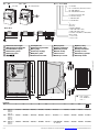
DC1-…-A66…
66 = IP66
DC1-…-A6S…
6S = IP66, switched
PWR
OFF
ON
REV
FWD
0
DC1-x yzzz F N-A66 N
N = Standard
CE1 =Coated Board, Enhanced, Version 1
66 = IP66, NEMA 4x
6S = IP66, NEMA 4x switched
B = Brake chopper (DC+, BR)
N = No Brake chopper
F = EMC Filter (RFI)
N = No EMC Filter
l
e
2D2 = 2.2 A
024 = 24 A
U
LN
(Mains), 50/60Hz
2 = 230 V (200 - 240 V ±10 %)
4 = 400 V (380 - 480 V ±10 %)
D = Doubler: 110 V (Mains) → 230 V (Motor)
Mains → Motor
1 = 1 AC → 3 AC
3 = 3 AC → 3 AC
L2
N
L1
L3
PE
L2
PEN
L1
L3
L2
N
L1
L3
en
de
fr
es
it
zh
ru
nl
da
el
pt
sv
fi
cs
et
hu
lv
lt
pl
sl
sk
bg
ro
hr
REV FWD
0
ON
OFF
PWR
b
a c
a1
c1
b1b2
a1
b1
⌀ 1
⌀ 2
a1
b1
→
1 inch = 25.4mm
1 mm = 0.0394 inch
1 inch = 1’’

Emergency On Call Service: Local representative (www.eaton.eu/aftersales) or +49 (0)180 5223822 (de, en) 3/12
07/16 IL04020013Z
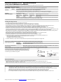
a, c Plastic – Kunststoff – Matière isolante – Plástico – Plastica – 塑料 – пластмасса – Kunststof – Kunststof –
Πλαστικό – Plástico – Plast – Muovi – Plast – Plastmaterjal– Műanyag – Plastmasa – Plastikas –
Tworzywo sztuczne – Umetna masa – Umelá hmota – Пластмаса – Plastic – Plastika
b Metal – Metall – Métal – Metal – Metallo – 金属 – металл – Metaal – Metal – Μέταλλο – Metal –
Metall – Metalli – Kov – Metall – Fém – Metāls – Metalas – Metall – Kovina – Kov – Метал –
Metal – Metal
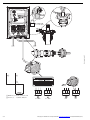
Mounting
Montage
Montage
Montaje
Montaggio
安
安装装
Монтаж
Montering
Montering
Τοποθέτηση
Montagem
Montering
Asennus
Montáž
Paigaldamine
Felszerelése
Montāža
Montavimas
Montaż
Montaža
Montáž
Монтаж
Montarea
Montaža
FS ⌀ mm (in) PG M
Control FS1
FS2
FS3
2 x 22 (0.87)
1 x 25 (0.98)
2 x PG 13.5
1 x PG 16
2 x M20
1 x M25
c LAPP SKINTOP CLICK (LAPP KABEL)
M20: 53112687
M25: 53112688
Power FS1 3 x 22 (0.87) 3 x PG 13.5 3 x M20 Cooper Crouse-Hinds GmbH
a Plastic (Mains)
M20: GHG9601955R0003 +
GHG9601941R0033
M25: GHG9601955R0004 +
GHG9601941R0034
b
Metal/EMC (Motor)
M20: CAP189202 (6 - 13 mm) + DKA12E
CAP189552 (4.5 - 10 mm) + DKA12E
M25: CAP189252 (10 - 18 mm) + DKA13E
CAP189562 (6 - 13 mm) + DKA13E
FS2
FS3
1 x 22 (0.87)
2 x 25 (0.98)
1 x PG 13.5
2 x PG 16
1 x M20
2 x M25
en
de
fr
es
it
zh
ru
nl
da
el
pt
sv
fi
cs
et
hu
lv
lt
pl
sl
sk
bg
ro
hr
c
a
c
REV FWD
0
ON
OFF
PWR
b
a
= 4 x M4
1 Nm (8.85 lb-in)
FS1, FS2, FS3
≦ 30°
≦ 30°
≦ 30°
≦ 30°
[mm (in)]
ab c
FS1 012.5 (0.49) 150 (5.91)
FS2 012.0 (0.47) 150 (5.91)
FS3 013.0 (0.51) 150 (5.91)
1 2
③
Control
PZ 2
1
2
3
③
Control
L2N
L3
U
V
W
L1N
1 2 3 4 5 6 7 8 9 10
1 2 3 4 5 6 7 8 9 10 11
Mains
Motor
①
②
en de fr es it zh ru nl da
el pt sv fi cs et hu lv lt
pl sl sk bg ro hr
en de fr es it zh ru nl da el pt
sv fi cs et hu lv lt pl sl sk bg
ro hr

4/12Emergency On Call Service: Local representative (www.eaton.eu/aftersales) or +49(0) 1805223822 (de, en)
07/16 IL04020013Z
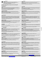
U1 V1 W1
W2 U2 V2
U
LN
= 230 V
U1 V1 W1
W2 U2 V2
U
LN
= 400 V
U1 V1 W1
W2 U2 V2
U1 V1 W1
W2 U2 V2
M
FWD
M
REV
②①
≧100 mm
(≧ 3.94")
① Power: L1, L2, L3, N, PE, U, V, W, DC+, BR
② Control: 1, 2, … 11, Modbus, CANopen
1410 mi n
230/400 V3.2/1.9 A
50 Hz
-1
0,75 KW
cosϕ 0.79
REV FWD
0
ON
OFF
PWR
1 2 3 4 5 6 7 8 9 10 11
PWR
OFF
ON
PES
⌀ = 5 mm → 2x
(⌀ = 0.20" → 2x)
⌀
Metal/EMC
UVWL1/N L2/N L3
⏚⏚

Emergency On Call Service: Local representative (www.eaton.eu/aftersales) or +49 (0)180 5223822 (de, en) 5/12
07/16 IL04020013Z
NOTICE
Connect only in voltage-free state!
VIGTIGT
Må kun tilsluttes i spændingsfri tilstand!
UZMANĪBU
Pieslēgt tikai tad, kad nenotiek sprieguma padeve!
ACHTUNG
Nur im spannungsfreien Zustand anschließen!
ΕΠΑΓΡΥΠΝΗΣΗ
Συνδέστε μόνο όταν δεν επικρατεί τάση!
DĖMESIO
Prijungti tik tada, kai išjungta įtampa!
ATTENTION
Raccordez l’appareil uniquement hors tension !
ADVERTÊNCIA
Ligar apenas com a tensão desligada!
UWAGA
Podłączać zawsze po uprzednimodłączeniuod zasilania elektrycznego!
CUIDADO
¡Conectar únicamente en estado sin tensión!
OBSERVERA
Får endast anslutas i spänningsfritt tillstånd!
POZOR
Napravo priključite le, ko ni pod napetostjo!
AVVISO
Collegare solo in assenza di tensione!
ILMOITUS
Kytke vain jännitteettömässä tilassa!
UPOZORNRNIE
Napájat˙ len v stave bez napätia!
注意
必须在断电状态下进行连接!
UPOZORNÉNÍ
Připojujte jen při zcela odpojeném napájení!
ПРЕДУПРЕЖДЕНИЕ
Свързвайте само, когато уреда не е под напрежение!
ВНИМАНИЕ
Подключать только в обесточенном состоянии!
TÄHELEPANU
Ühendada ainult pingevabas olekus!
ATENTJE
Conectaţi doar când aparatul nu se află sub tensiune!
OPGELET
Alleen in spanningsloze toestand aansluiten!
FIGYELEM
Csak feszültségmentes állapotban csatlakoztassa!
POZOR
Priključujte samo u beznaponskom stanju!
Mains 1 ~Mains 3 ~Motor Brake Resistor
FS1
A1 = 8 mm (0.31")
FS2, FS3
A1 = 10 mm (0.39")
en da lv
de el lt
fr pt pl
es sv sl
it fi sk
zh cs bg
ru et ro
nl hu hr
PE
A1
PE
A1
PE
A1
PE
A1
UVWL1/N L2/N L3
⏚⏚
≧ 90 mm
(≧ 3.54")
MotorMain
PES
L2N
L3
U
V
W
L1N
1 2 3 4 5 6 7 8 9 10
1 2 3 4 5 6 7 8 9 10 11
PH2
1 Nm
(8.85 lb-in)

6/12Emergency On Call Service: Local representative (www.eaton.eu/aftersales) or +49(0) 1805223822 (de, en)
07/16 IL04020013Z
Framel
LN
F1/Q1Mains l
2
Motor PR
B
SizeMCB (type B)
AA mm
2
AWGA mm
2
AWGkWHP Ω mm
2
AWG
DC1-12011…FS2 19.2 25 41010.5 1.5 16 2.2 3501.5 16
DC1-12015…FS3 29.2 40 6815.3 2.5 14 4525 1.5 16
DC1-122D3… FS1 3.7 10 (6) 1.5 16 2.3 1.5 16 0.370.5 ---
DC1-124D3… FS1, FS27.5 10 1.5 16 4.31.5 16 0.75 1100 1.5 16
DC1-127D0… FS1, FS212.9 16 (17.5) 2.5147 1.5 16 1.5 2100 1.5 16
DC1-1D2D3…FS1 7.8 10 2.5 14 2.3 2.5140.370.5 ---
DC1-1D4D3…FS1 15.8 25 4104.3 4120.751 ---
DC1-1D5D8…FS2 21.9 32 (30)6 85.8 6101.1 1.5100 1.5 16
DC1-32018… FS3 20.9 32 (30) 6818 2.5 14 4525 1.5 16
DC1-322D3… FS1 3.4 61.5 16 2.3 1.5 16 0.370.5 ---
DC1-324D3… FS1, FS25.6 10 1.5 16 4.31.5 16 0.75 1100 1.5 16
DC1-327D0… FS1, FS29.5 16 (15)1.5 16 71.5 16 1.52 1001.5 16
DC1-327D0… FS2 12.1 16 (17.5) 2.5 14 10.5 1.5 16 2.2 3501.5 16
DC1-34014… FS3 17.2 25 410142.5 14 5.5 7.5 1002.5 14
DC1-34018… FS3 21.2 32 (30) 410182.5 14 7.5 10 80 2.5 14
DC1-342D2… FS1, FS23.5 61.5 16 2.2 1.5 16 0.75 1501.5 16
DC1-344D1…FS1, FS25.6 10 1.5 16 4.1 1.5161.5 2250 1.5 16
DC1-345D8…FS2 7.516 (10) 1.5 16 5.8 1.5162.2 3200 1.5 16
DC1-349D5… FS211.5 16 (15) 2.5 14 9.5 1.5 16 451201.5 16
→
M2.5
mm
2
mm
2
AWG mm in Nm lb-in mm
0.2 - 2.5 0.2 - 1.5 24 - 12 5 0.2 0.4 3.54 0.4 x 2.5
≦ 20 m (≦ 65.62 ft)
≧ 120 mm (≧ 4.72")
5
+10 VAI1 0 V
Drive relay output
250 V ∼ ≦ 6 A
30 V ⎓ ≦ 5 A
DI2 DI3
6734
4K7
+24 V
≦ 20 m
(≦ 65.62 ft)
DI1
12
10 11
98
f-Out
+
0...+10 V
0 V
K13
K14
AO
< 20 mA
+
-
Run
I
K1
AC
DC
AC
Varistor
(+)
(
-
)
DC
Diode
AC
RC filter
PES
MM
FWD REV
RJ45
X1
PIN 8
(PIN 2)
PIN 7
(PIN 1)
RS485
L2N
L3
U
V
W
L1N
1 2 3 45 6789 10
1 2 3 4 5 6 7 8 9 10 11
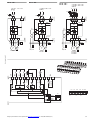
PIN 1CANopen -
PIN 2CANopen +
PIN 30V
PIN 4OP-Bus -
PIN 5OP-Bus +
PIN 6+24 V
PIN 7Modbus RTU (A), RS485-
PIN 8Modbus RTU (B), RS485+

Emergency On Call Service: Local representative (www.eaton.eu/aftersales) or +49 (0)180 5223822 (de, en) 7/12
07/16 IL04020013Z
DC1-1D…-A66… DC1-12…-A66…
L1/L
L2/N
VAR
3 AC 230 V
WVU
M
I
2
3 ~
1 AC 110 V - 115 V ± 10%
50/60 Hz
L
F1
N
PES
I
2
DC+
BR
3 AC 230 V
EMC
VAR
PES
①
WVU
①
FS2, FS3
M
3 ~
L
F1
N
L1/L
L2/N
1 AC 200 V - 240 V ± 10%
50/60 Hz
I
2
DC+
BR
3 AC 230 V
3 AC 400 V
3 AC 460 V
EMC
VAR
PES
①
L1/L
L3
L2/N
3 AC 200 V - 240 V ± 10%
3 AC 380 V - 480 V ± 10%
50/60 Hz
WVU
①
FS2, FS3
M
3 ~
L1 L2 L3
Q1
III
DC1-32…-A66…
DC1-34…-A66…
2
DI1
FWD
+24 V
3
DI2
REV
4
DI3
AI2
FF1
5
+10 V Out
< 10 mA
+10 V
6
AI1
DI4
f-Soll
7
0 V
1
+24 V Out
< 100 mA
8
0...+10 V
< 20 mA AO
+24 V DO
f-Out
+
9
0 V
PIN 8
(PIN 2)
PIN 7
(PIN 1)
10 11
RUN
6 A, 250 VAC
5 A, 30 VDC
RS485
CPU
0...+10 V
X1
1 2 3 4 5 6 7 8 9 10 11
12345678910 11
+24 V
DI1
AI1
0 V
DI2
DI3
AO1
0 V
K13
K14
+10 V

8/12Emergency On Call Service: Local representative (www.eaton.eu/aftersales) or +49(0) 1805223822 (de, en)
07/16 IL04020013Z
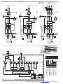
DC1-1D…-A6S… DC1-12…-A6S…
L1/L
L2/N
VAR
3 AC 230 V
WVU
M
I
2
3 ~
1 AC 110 V - 115 V ± 10%
50/60 Hz
L
F1
PWR
N
PES
EMC
VAR
WVU
M
I
2
3 ~
PES
I
2
DC+
BR
L1/L
L2/N
1 AC 200 V - 240 V ± 10%
50/60 Hz
L
F1
N
3 AC 230 V
PWR
I
2
DC+
BR
3 AC 230 V
3 AC 400 V
3 AC 460 V
EMC
VAR
PES
①
L1/L
L3
L2/N
3 AC 200 V - 240 V ± 10%
3 AC 380 V - 480 V ± 10%
50/60 Hz
WVU
①
FS2, FS3
M
3 ~
L1 L2 L3
Q1
III
PWR
DC1-32…-A6S…
DC1-34…-A6S…
2
DI1
FWD
24 V
3
DI2
REV
4
DI3
AI2
5
+10 V Out
< 10 mA
10 V
6
AI1
DI4
f-Soll
7
0 V
1
+24 V Out
< 100 mA
REV
OFF
FWD
8
0...+10 V
< 20 mA AO
+24 V DO
9
0 V
10 11
6 A, 250 VAC
5 A, 30 VDC
CPU
0...+10 V
①
②
PIN 8
(PIN 2)
PIN 7
(PIN 1)
RS485
X1
1 2 3 4 5 6 7 8 9 10 11
12345678910 11
+24 V
DI1
AI1
0 V
DI2
DI3
AO1
0 V
K13
K14
+10 V
BK
WH
GN
YE
BU
RD
→ DIN IEC 304, DIN IEC 60 757
1RD2
2BU6
3YE4
5GN5
6WH9
7BK0

Emergency On Call Service: Local representative (www.eaton.eu/aftersales) or +49 (0)180 5223822 (de, en) 9/12
07/16 IL04020013Z
DC1-…-A66…
DC1
U
Boost
[%]
U
Motor
[V]
P-08
I
Motor
[A]
P-09
f
Motor
[Hz]
P-01
f
max
[Hz]
P-02
f
min
[Hz]
P-11
P-07
P-03 acc [s]
1 2
34
567
8
9
10 11
DI1: FWD
DI2: REV
DI3: FF1
+24 V/100 mA
+10 V/10 mA
AI1: f-Ref.
0 V
AO: f-Out
30 V DC/5 A
250 V AC/6 A
0 V
4.7 kΩ
0 -10 V
20 mA
DC1
1410 min
230/400 V3.2/1.9 A
50 Hz
-1
0.75 kW
cosϕ 0.79
P-07
P-08
P-10
P-09
START
STOP
Speed/Frequency
Stop
> 1 s
4 x
> 1 s
1
Enable
(Example)
Herz Ampere Herz
2
or
12
STOP
Motor
> 1 s
1 x
> 1 s
n x
START
Motor
Motor Start FWD
STOP

10/12 Emergency On Call Service: Local representative (www.eaton.eu/aftersales) or +49(0) 1805223822 (de, en)
07/16 IL04020013Z
DC1-…-A6S…
Thermistor
Thermistor
Thermistance
Termistor
Termistore
热热敏敏电电阻阻
Термистор
Thermistor
Thermistor
Θερμίστορ
Thermistance
Termistor
Termistori
Termistor
Termistor
Termisztor
Termistors
Termistorius
Termistor
Termistor
Te
rm
isto
r
Термистор
Termistor
Termistor
DC1
U
Boost
[%]
U
Motor
[V]
P-08
I
Motor
[A]
P-09
f
Motor
[Hz]
P-01
f
max
[Hz]
P-02
f
min
[Hz]
P-11
P-07
P-03 acc [s]
REV FWD
0
ON
OFF
PWR
Speed Reference
f
min -
f
max
P-02 - P-01
(0 - 50 Hz)
RUN
Reverse
RUN
Forward
Mains switch
1410 min
230/400 V3.2/1.9 A
50 Hz
-1
0.75 kW
cosϕ 0.79
P-07
P-08
P-10 P-09
(Example)
or
STOP
Motor
n x
Motor Start FWD
Ampere Herz
STOP
REV FWD
0
n x
Motor Start REV
REV FWD
0
Herz
REV FWD
0
0
> 1 s
4 x
> 1 s
en
de
fr
es
it
zh
ru
nl
da
el
pt
sv
fi
cs
et
hu
lv
lt
pl
sl
sk
bg
ro
hr
T1 T2
M3∼
Thermoclick sensor
ϑ
ϑ
UVWPE
PTC type
≧ 2.5 kΩ trip level
≦ 1.9 kΩ Reset
PES
1234567891011
+
P-
+
P-
→→ →
Error: External Fault
P-12 = 0
P-15 = 3, 6, 7, 13
Terminal 4: DI3
E-triP

Emergency On Call Service: Local representative (www.eaton.eu/aftersales) or +49 (0)180 5223822 (de, en) 11/12
07/16 IL04020013Z
Additional Information for UL
®
Approved Installations
→ Refer to Manual MN04020003Z-EN and MN040023EN.
DC1 is designed to meet the UL requirements. In order to ensure full compliance, the following must be fully observed.
–For 1 phase supply, power should be connected to L1/2 and L2/N.
–For 3 phase supplies, power should be connected to L1, L2, and L3. Phase sequence is not important.
–For compliance with CE and C Tick EMC requirements, a symmetrical shielded cable is recommended.
–Afixed installation is required according to IEC61800-5-1 with a suitable disconnecting device installed between the DC1 and the AC Power Source.
The disconnecting device must conform to the local safety code/regulations (e. g. within Europe, EN60204-1, Safety of machinery).
–The cables should be dimensioned according to any local codes or regulations. Guideline dimensions are given on page6.
–Suitable fuses to provide wiring protection of the input power cable should be installed in the incoming supply line, according to the data on page6.
The fuses must comply with any local codes or regulations in place. In general, type gG (IEC 60269) or UL Class CC or Class J fuses are suitable; however in some
cases type aR fuses may be required. The operating time of the fuses must be below 0.5 seconds. The max. voltage rating for fuses is 600 V.
–Where allowed by local regulations, suitably dimensioned type B MCB circuit breakers of equivalent rating may be utilised in place of fuses, providing that the
clearing capacity is sufficient for the installation. The max. voltage rating for breakers is 480 V.
–When the power supply is removed from the drive, a minimum of 30 seconds should be allowed before re-applying the power.
A minimum of 5 minutes should be allowed before removing the terminal covers or connection.
–The maximum permissible short circuit current at the DC1 Power terminals as defined in IEC60439-1 is 100 kA.
–An optional Input Choke is recommended to be installed in the supply line for drives where any of the following conditions occur:
– The incoming supply impedance is low or the fault level/short circuit current is high.
– The supply is prone to dips or brown outs.
– An imbalance exists on the supply (3 phase drives).
–In all other installations, an input choke is recommended to ensure protection of the drive against power supply faults.
Input Power Supply Requirements
Supply Voltage DC1-12… 200 - 240 RMS Volts for 230 Volt rated units, ±10 % variation allowed. 240 Volt RMS Maximum
DC1-34… 380 - 480 Volts for 400 Volt rated units, ±10 % variation allowed, Maximum 500 Volts RMS
Imbalance Maximum 3 % voltage variation between phase – phase voltages allowed
All DC1 units have phase imbalance monitoring. A phase imbalance of > 3 % will result in the drive tripping.
For input supplies which have supply imbalance greater than 3 % Eaton Drives recommends the installation of input line reactors.
Frequency 50 - 60 Hz ±5 % Variation
Short Circuit Capacity Voltage Rating Min. kW (HP) Max. kW (HP) Maximum supply short-circuit current
230 V7.5 (10) 11 (15) 100 kA rms (AC)
400/460 V15 (20) 22 (30) 100 kA rms (AC)
All the drives in the above table are suitablefor use on a circuit capable of delivering not more than the above specified maximum
short-circuit Amperes symmetrical with the specified maximum supply voltage.
Incoming power supply connection
All DC1 units are intended for indoor installation within controlled environments which meet the condition limits.
Ambient temperature range Operational -10 °C to 50 °C (14 °F to 122 °F), to 60 °C (140 °F) with derating
Storage and
Transportation
-40 °C to 60 °C (-40 °F to 140 °F)
Max. altitude for rated operation 1000 m (Refer to Manual for Derating for Altitude Information). Installation above 2000 m is not UL approved.
Relative Humidity < 95 % (non condensing). Drive must be Frost and moisture free at all times.
Branch circuit protection must be installed according to the relevant national codes. Fuse ratings and types are shown on page 6.
Suitable Power and motor cables should be selected according to the data.
Power cable connections and tightening torques are shown on page 6.
Only a single conductor type is allowed in each field wiring terminal when
connected in group installation arrangement.
Motor Overload Protection
DC1 provides motor overload protection in accordance with the National Electrical Code (US).
–Where a motor thermistor is not fitted, or not utilised, Thermal Overload Memory Retention must be enabled by setting P-51 = 0
Set the parameters P1-08 „Current Limit“ on motor current.
–Where a motor thermistor is fitted and connected to the drive, connection must be carried out according to the information, refer to Manual.
→
–Ratings shown above apply to 50 °C (122 °F) Ambient temperature. For derating information, refer to Manual.
–The maximum motor cable length stated applies to using a shielded motor cable. When using an unshielded cable, the maximum cable length limit may be
increased by 50 %. When using the Eaton Drives recommended output choke, the maximum cable length may be increased by 100 %
–The PWM output switching from any inverter when used with a long motor cable length can cause an increase in the voltage at the motor terminals,
depending on the motor cable length and inductance. The rise time and peak voltage can affect the service life of the motor.
Eaton Drives recommend using an output choke for motor cable lengths of 50 m or more to ensure good motor service life
–For UL compliant installation, use Copper wire with a minimum insulation temperature rating of 75 °C (167 °F), UL Class CC or Class J fuses.
Terminal (ring lug)
Cable
Cable support
Cable
Cable
PE

12/12 Emergency On Call Service: Local representative (www.eaton.eu/aftersales) or +49(0) 1805223822 (de, en)
07/16 IL04020013Z
Eaton Industries GmbH, Hein-Moeller-Straße 7-11, 53115 Bonn, Germany
©2013 by Eaton Industries GmbH,
www.eaton.eu/documentation
All Rights Reserved
07/16 IL04020013Z ETN
Printed in the UK (07/16)
CAUTION
In the territory of the EU Directive the frequency-controlled devices
andtheir accessories must be taken into operation only when the machine
has been determined to filfil the protection requirements of
Machinery Safety Directive 89/392/EEC.
HUOMIO
EU-direktiivien voimassaoloalueella taajuusohjatut laitteet ja niiden varusteet saa ottaa
käyttöön vain silloin, kun todetaan, että kone täyttää konedirektiivin 89/392/ETY
suojausvaatimukset.
EMC-mukainen rakenne. Ohjaus- ja verkkojohdot on asennettava tilaulotteisesti erotettuina.
Johdonsuoja on liitettävä laajasti maadoitukseen
p
.
Ensure EMC-compliant installation. Lay control and communication cables spatially
separated from the motor cable. Ensure a large contact area connection between
p
cable screen and PE.
VORSICHT
Im Geltungsbereich der EG-Richtlinien dürfen die frequenzgesteuerten Geräte und deren
Zubehör nur dann in Betrieb genommen werden, wenn festgestellt wird,dass die Maschine die
Schutzanforderungen der Maschinenrichtlinie 89/392/EWG erfüllt.
EMV-gerechter Aufbau. Steuer- und Netzleitungen räumlich getrennt von der Motorleitung
verlegen.
p
Leitungsschirm großflächig mit PE verbinden.
POZOR
V rozsahuplatnostisměrnicESsmíbýtfrekvenčně řízenépřístroje a jejich příslušenstvíuvedeny
do provozu jedině tehdy, pokud je zjištěno, že stroj splňuje požadavky ochrany stanovené
směrnicí 89/392/EHS o strojních zařízeních.
Nástavba odpovídající směrnici EMC. Řídicí a sít’ová vedení pokládejte prostorově oddělená od
vedení motoru.
p
Stínění vedení spojte velkoplošně s PE.
AVERTISSEMENT
En application des directives européennes, les convertisseurs de fréquence et leurs
accessoires ne doivent être mis en service que s’il a été vérifié que la machine répond aux
exigences de la directive machines 89/392/CEE.
Montage conforme aux règles de la CEM. Eloigner les câbles de commande et de réseau des
câbles puissance. Relier le blindage au PE en assurant de grandes surfaces de contact.
ETTEVAATUST
EÜ-direktiivi kehtivuspiirkonnas võib sagedusjuhitavaid seadmeid ja nende lisaseadmeid
kasutusele võtta ainult siis, kui on kindlaks tehtud, et masin vastab masinadirektiivi 89/392/EMÜ
kaitsenõuetele.
Elektomagnetilisele ühilduvusele vastav ehitus. Juhtimis- ja võrgukaablid paigaldada mootori
toitekaablist ruumiliselt eraldatuna.
p
Kaabli kaitseekraan ühendada ulatuslikult
talitlusmaandusega.
ATENCIÒN
En el campo de aplicaciónde la normativa CE, los dispositivos controlados por frecuencia y sus
correspondientes accesorios sólo deberán ponerse en marcha cuando se asegure que la
máquina cumple con las exigencias de seguridad de la normativa de máquinas 89/392/CEE.
El montaje debe cumplir CEM. Los cables de mando y de conexión a red se deben instalar
independientementedel cable de conexión al motor. El cable apantallado
p
se debeconectar
a masa utilizando una amplia superficie de contacto.
VIGYÁZAT
Az EK irányelvek hatályossági területén a frekvenciavezérelt készülékeket és azok tartozékait
csak akkor szabad üzembe helyezni, ha megállapítást nyert, hogy a gép megfelel a gépek
biztonságáról szóló, 89/392/EGK számú irányelv biztonsági követelményeinek.
Elektromágnesesen összeférhető kivitelt biztosítson. A motorvezetékektől térben elkülönítve
vezesse vezérlő és hálózati vezetékeket.
p
Nagy felületen csatlakoztassa a védőföldeléshez
a vezetékárnyékolást.
ATTENZIONE
Nel campo di validitàdelle direttive CE, gli apparecchia controllo di frequenza e i loro accessori
possono essere messi in esercizio soltanto se si verifica che la macchina soddisfa i requisiti di
sicurezza della direttiva macchine 89/392/CEE
Montaggio secondo CEM. Disporre i cavi comandi e di alimentazione separati dal cavo del
motore. Collegare lo schermo del cavo
p
con PE con un’ampia superficie.
IEVĒROT PIESARDZĪBU
Valstīs, kurās ir spēkā EK direktīvas, ierīču ar frekvenčvadību un to piederumu ekspluatāciju
drīkst sākt tikai tad, ja ir konstatēta iekārtas atbilstība Mašīnu direktīvā 89/392/EEK ietvertajām
aizsardzības prasībām.
EMS atbilstoša uzbūve. Vadības un tīkla kabeļus izvietot atsevišķi no motora kabeļa.
p
Vada ekrānu plašā virsmā savienot ar PE.
小小心心
根据欧盟设备一致性规范,安装频率控制设备及其配件时,应确保设备满足机器规
范89/392/EWG 中关于设备保护的要求。
p
按照电磁兼容规范正确安装。应将控制电缆和电源电缆与电机电缆分开。
大面积采用PE包裹电缆。
ATSARGIAI
EB direktyvų taikymo srityje dažniniu būdu valdomus įrenginius ir jų priedus leidžiama pradėti
naudoti tik tada, kai nustatoma, kad įrenginys atitinka Mašinų direktyvos 89/392/EEB keliamus
apsaugos reikalavimus.
MontažasturiatitiktiEMSreikalavimus.Valdymoirduomenų tinklo kabelius išdėstyti atokiai nuo
variklio kabelio.
p
Kabelio ekraną dideliu paviršiumi sujungti su įžeminimu.
ОСТОРОЖНО
В сфере действия директив ЕС устройства с частотным управлением и их оснащение
должны вводиться в эксплуатацию только в том случае, если установлено, что данное
оборудование соответствует требованиям по защите Директивы о машинном
оборудовании 89/392/EWG.
Сборка соответственно электромагнитной совместимости. Линии управления и
электросети прокладывать в пространственном отношении отдельно от линии двигателя.
p
cиловой экран соединять с PE по большой площади.
OSTROŻNIE
Na obszarze obowiązywania dyrektyw WE urządzenia sterowane częstotliwościowo wolno
wprowadzać do eksploatacji tylko wtedy, gdy zostanie stwierdzone, że maszyna spełnia
wymagania ochronne dyrektywy maszynowej 89/392/EWG.
Konstrukcja zgodna z dyrektywą w sprawie kompatybilności elektromagnetycznej (EMC).
Przewody sterowania i zasilania elektrycznego należy układać oddzielnie od przewodu silnika.
p
Ekranowanie połączyć z przewodem uziemiającym na większej powierzchni.
VOORZICHTIG
Binnen het geldigheidsgebied van de EC-richtlijnen mogen de frequentiegeregelde apparaten
en de toebehoren daarvan alleen in bedrijf worden genomen, wanneer wordt vastgesteld, dat
de machine aan de veiligheidseisen van de machinerichtlijn 89/392/EWG voldoet.
EMC-conforme constructie. Besturings- en netkabels ruimtelijk gescheiden van de motorkabel
leggen.
p
Kabelafscherming over groot oppervlak met PE verbinden.
PREVIDNO
Na območju veljavnosti direktiv ES je zagon frekvenčno krmiljenih naprav in
njihovega pribora dovoljen le tedaj, ko je bilo ugotovljeno, da stroj ustreza varnostnim zagtevam
Direktive o strojih 89/392/EGS.
Montaža v skladu z EMZ. Krmilne in omrežne vodnike napeljite ločeno od vodnikov motorja.
p
Oklep vodnika na veliki površini povežite z zaščitnim vodnikom.
FORSIGTIG
I det område, hvor EF-direktiverne er gældende, må det frekvensstyrede udstyr og dets tilbehør
kun tages i anvendelse, hvis det konstateres, at maskinen opfylder beskyttelseskravene i
maskindirektivet 89/392/EØF.
EMC-korrekt installation. Træk styre- og netledninger rumligt adskilt fra motorledningen.
p
Sørg for en stor kontaktflade mellem PES ledningsafskærmning og PE.
VÝSTRAHA
V krajinách, ktoré spadajú pod pôsobnosťsmernícES smú byť rádiovo ovládané zariadeniaa ich
príslušenstvo uvedené do prevádzky len ak je zabezpečené, že stroj spĺňa ochranné
ustanovenia smernice č. 89/392/EHS o strojových zariadeniach.
Montáž v súlade s požiadavkami elektromagnetickej kompatibility. Ovládacie a siet˙ové vedenia
uložte v priestore oddelene od vedenia motora.
p
Zabezpečte veľkú kontaktnú plochu medzi
káblovým tienením a PE.
ΠΡΟΣΟΧΗ
Στο πεδίο εφαρμογής των οδηγιών της ΕΚ, οι ελεγχόμενες μέσω συχνότητας συσκευές και τα
παρελκόμενά τους επιτρέπεται να τίθενται σε λειτουργία μόνο εφόσον διαπιστωθεί ότι το
μηχάνημα πληροί τις απαιτήσεις προστασίας της οδηγίας της ΕΚ για τα μηχανήματα 89/392/ΕΟΚ.
Κατασκευή σύμφωνα με τις απαιτήσεις ΗΜΣ. Εγκαθιστάτε τους αγωγούς ελέγχου και δικτύου
ανεξάρτητα από τον αγωγό του κινητήρα.
p
Συνδέετε τη θωράκιση των αγωγών σε μεγάλη
επιφάνεια με τη γείωση.
ВНИМАНИЕ
В сферата на действие на изискванията на ЕС устройствата с честотно управление и
техните допълнителни устройства могат да бъдат приведени в употреба, само ако се
установи, че оборудването съответства на изискванията за безопасност на машинно
оборудване спрямо 89/392/EWG.
Монтаж с електромагнитна съвместимост. Полагане на контролните и мрежови
проводници пространствено отделно от проводника на двигателя.
p
Осигурете
по-голяма конкактна площ между силовия екран и PE.
CUIDADO
No âmbito das directivas da CE, os aparelhos comandados por frequência e os respectivos
acessórios só podem ser postos em operação se for comprovado que a máquina atende às
exigências de protecção da directiva de máquinas 89/392/CE.
Estrutura com compatibilidade electromagnética. Dispor os fios de comando e de rede
separados do fio do motor.
p
Ligar uma área grande da blindagem do cabo (PES) com o PE.
PRECAUTJE
În cadrul sferei de aplicare a directivelor UE dispozitivele controlate prin frecvenţă şi
accesoriile acestora au voie să fie puse în funcţiune doar dacă se stabileşte că aparatul
îndeplineşte cerinţele Directivei 89/392/CEE privind maşinile.
Montajul trebuie să fie compatibil EMC. Poziţionaţi cablurile de control şi de reţea la distanţă de
cablul motorului.
p
Asiguraţi o suprafaţă de contact mare între izolaţia cablului şi PE.
FÖRSIKTIG
I giltighetsområdet för EG-direktiven får de frekvensstyrda apparaterna och deras
tillbehör endast tagas i drift när man fastställt att maskinen uppfyller skyddskraven i
maskindirektiv 89/392/EEC.
EMC-anpassad uppbyggnad. Styr- och nätledningar dras avskilda från motorledningarna.
p
Förbind ledningsskärm över ett brett område med PE.
OPREZ
U području valjanosti Direktiva EZ frekvencijski upravljani uređaji i njihov pribor smiju se
puštati u rad samo ako se utvrdi da stroj ispunjava zahtjeve za zaštitom iz Direktive o
strojevima 89/392/EEZ.
Konstrukcija u skladu s EMC-om. Upravljački i mrežni vodovi prostorno položeni odvojeno od
voda motora.
p
zaslon kabela povezan PE-om na velikoj površini.
en
fi
de
cs
fr et
es hu
it lv
zh
lt
ru pl
nl sl
da sk
el bg
pt ro
sv hr
-
 1
1
-
 2
2
-
 3
3
-
 4
4
-
 5
5
-
 6
6
-
 7
7
-
 8
8
-
 9
9
-
 10
10
-
 11
11
-
 12
12


Eaton DL1-34061 Series Instruction Leaflet
- Tip
- Instruction Leaflet
Lucrări înrudite
-
Eaton DX-CBL-PC-1M5 Instruction Leaflet
-
-
-
-
-
-
-
-
-
Eaton DA1-32030 Series Instruction Leaflet
Alte documente
-
DeLOCK 60232 Fișa cu date
-
 EATON CUTLER HAMMER SL7-AP24 Instrucțiuni de utilizare
-
LG PMBUSB00A Manualul proprietarului
-
Maico MVS 6 Mounting And Operating Instructions
-
Elko TEV-4 Manual de utilizare
-
Elko COS-2 Manual de utilizare
-
Dean DC0001 Manualul proprietarului
-
Silvercrest RFH 2401 User Manual And Service Information
-
ABB MS132-K Ghid de instalare
