
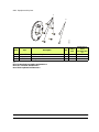
Index revision : C - March 2018 1 7108
User manual
SAMES KREMLIN SAS - 13, Chemin de Malacher - 38240 MEYLAN - FRANCE
Tel. 33 (0)4 76 41 60 60 - www.sames-kremlin.com
Nanobell II WB

Index revision : C - March 2018 2 7108
All communication or reproduction of this document, in any form whatsoever and all use or
communication of its contents are forbidden without express written authorisation from
SAMES KREMLIN.
The descriptions and characteristics mentioned in this document are subject to change without
prior notice.
© SAMES KREMLIN 2015
WARNING : SAMES KREMLIN SAS is registered with the Ministry of Labour as a training
institution.
Throughout the year, our company offers training courses in the operation and
maintenance of your equipment.
A catalogue is available on request. Choose from a wide range of courses to
acquire the skills or knowledge that is required to match your production
requirements and objectives.
Our training courses can be delivered at your site or in the training centre at our
Meylan head office.
Training department:
Tel. 33 (0)4 76 41 60 04
E-mail: formation-clie[email protected]
SAMES KREMLIN SAS operating manuals are written in French and translated into English, German, Spanish, Italian
and Portuguese.
The French version is deemed the official text and Sames will not be liable for the translations into other languages.

Index revision : 3
Nanobell II WB
1. Health and Safety Instructions- - - - - - - - - - - - - - - - - - - - - - - - - - - - 5
1.1. Configuration of the certified equipment . . . . . . . . . . . . . . 5
1.2. Marking on the atomizer . . . . . . . . . . . . . . . . . . . . . . . . . . . . 5
1.3. Precautions for Use . . . . . . . . . . . . . . . . . . . . . . . . . . . . . . . . . 6
1.4. Warnings . . . . . . . . . . . . . . . . . . . . . . . . . . . . . . . . . . . . . . . . . . 6
1.4.1. Installation rules . . . . . . . . . . . . . . . . . . . . . . . . . . . . . . . . . . . . . 10
1.5. Important Recommendations . . . . . . . . . . . . . . . . . . . . . . 11
1.5.1. Compressed Air Quality . . . . . . . . . . . . . . . . . . . . . . . . . . . . . . 11
1.5.2. Product Quality . . . . . . . . . . . . . . . . . . . . . . . . . . . . . . . . . . . . . 11
1.5.3. Bearing Safety . . . . . . . . . . . . . . . . . . . . . . . . . . . . . . . . . . . . . . 11
1.5.4. Locking . . . . . . . . . . . . . . . . . . . . . . . . . . . . . . . . . . . . . . . . . . . . 12
1.5.5. Shaping Air. . . . . . . . . . . . . . . . . . . . . . . . . . . . . . . . . . . . . . . . . 12
1.5.6. High Voltage . . . . . . . . . . . . . . . . . . . . . . . . . . . . . . . . . . . . . . . 12
1.5.7. Maximum Speed. . . . . . . . . . . . . . . . . . . . . . . . . . . . . . . . . . . . 12
1.5.8. Vibrations . . . . . . . . . . . . . . . . . . . . . . . . . . . . . . . . . . . . . . . . . . 12
1.5.9. Bell Cup / Turbine Fitting. . . . . . . . . . . . . . . . . . . . . . . . . . . . . . 12
1.5.10. O-ring Seals . . . . . . . . . . . . . . . . . . . . . . . . . . . . . . . . . . . . . . . 13
1.5.11. Ventilation . . . . . . . . . . . . . . . . . . . . . . . . . . . . . . . . . . . . . . . . 13
1.5.12. Residual pressure. . . . . . . . . . . . . . . . . . . . . . . . . . . . . . . . . . . 13
1.5.13. Safety devices . . . . . . . . . . . . . . . . . . . . . . . . . . . . . . . . . . . . . 13
1.5.14. Restriction on robot wrist movements. . . . . . . . . . . . . . . . . . 13
1.5.15. Mechanical Collision. . . . . . . . . . . . . . . . . . . . . . . . . . . . . . . . 13
1.5.16. Ambient Temperature . . . . . . . . . . . . . . . . . . . . . . . . . . . . . . 13
1.5.17. Sound level. . . . . . . . . . . . . . . . . . . . . . . . . . . . . . . . . . . . . . . . 13
1.5.18. Specific maintenance provisions . . . . . . . . . . . . . . . . . . . . . 14
1.6. Guarantee . . . . . . . . . . . . . . . . . . . . . . . . . . . . . . . . . . . . . . . 15
2. Description - - - - - - - - - - - - - - - - - - - - - - - - - - - - - - - - - - - - - - - - - 16
2.1. General . . . . . . . . . . . . . . . . . . . . . . . . . . . . . . . . . . . . . . . . . 16
2.2. Function of the parts . . . . . . . . . . . . . . . . . . . . . . . . . . . . . . . 18
3. Technical Characteristics - - - - - - - - - - - - - - - - - - - - - - - - - - - - - - 19
3.1. Dimensions, gravity center and tool center point (mm) . 19
3.1.1. Hollow wrist version . . . . . . . . . . . . . . . . . . . . . . . . . . . . . . . . . . 19
3.1.2. Full wrist version . . . . . . . . . . . . . . . . . . . . . . . . . . . . . . . . . . . . . 21
3.2. Working characteristics . . . . . . . . . . . . . . . . . . . . . . . . . . . . 23
3.3. Operating Principle . . . . . . . . . . . . . . . . . . . . . . . . . . . . . . . . 24
3.3.1. Turbine . . . . . . . . . . . . . . . . . . . . . . . . . . . . . . . . . . . . . . . . . . . . 24
3.3.2. Turbine Rotation Speed . . . . . . . . . . . . . . . . . . . . . . . . . . . . . . 25
3.3.3. Microphone . . . . . . . . . . . . . . . . . . . . . . . . . . . . . . . . . . . . . . . . 25
4. Diagrams - - - - - - - - - - - - - - - - - - - - - - - - - - - - - - - - - - - - - - - - - - 26
5. Startup - - - - - - - - - - - - - - - - - - - - - - - - - - - - - - - - - - - - - - - - - - - - 28
5.1. Tools . . . . . . . . . . . . . . . . . . . . . . . . . . . . . . . . . . . . . . . . . . . . 28
5.2. Installation . . . . . . . . . . . . . . . . . . . . . . . . . . . . . . . . . . . . . . . 30
5.3. Shutdown and Startup Procedures . . . . . . . . . . . . . . . . . . . 31
5.3.1. Shutdown Procedure . . . . . . . . . . . . . . . . . . . . . . . . . . . . . . . . 31
5.3.2. Startup Procedure. . . . . . . . . . . . . . . . . . . . . . . . . . . . . . . . . . . 31

Index revision : 4
6. Maintenance - - - - - - - - - - - - - - - - - - - - - - - - - - - - - - - - - - - - - - - 32
6.1. Summary table of maintenance operations . . . . . . . . . . . 32
6.2. Preventive maintenance . . . . . . . . . . . . . . . . . . . . . . . . . . . 33
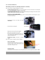
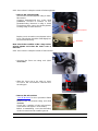
6.2.1. Procedure A: Atomizer exterior . . . . . . . . . . . . . . . . . . . . . . . . 33
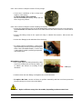
6.2.2. Procedure B1: Magnetic bell cup. . . . . . . . . . . . . . . . . . . . . . 35
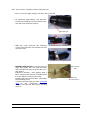
6.2.3. Procedure B2: Shaping air assembly. . . . . . . . . . . . . . . . . . . . 36
6.2.4. Procedure B3: Injector / Injector holder assembly . . . . . . . . 37
6.3. Corrective maintenance . . . . . . . . . . . . . . . . . . . . . . . . . . . 38
6.3.1. Procedure C1: Body installation / removal . . . . . . . . . . . . . . 38
6.3.2. Procedure C2: Replacement of turbine. . . . . . . . . . . . . . . . . 38
6.3.3. Procedure C3: Replacement of solvent pipette. . . . . . . . . . 39
6.3.4. Procedure C4: Replacement of microvalves . . . . . . . . . . . . 39
6.3.5. Procedure C5: Replacement of body o-rings . . . . . . . . . . . . 40
6.3.6. Procedure C6: Replacement of fittings and hoses. . . . . . . . 40
6.3.7. Procedure C7: Replacement of the placebo. . . . . . . . . . . . 41
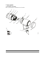
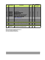
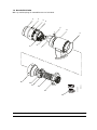
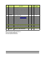
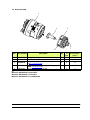
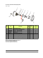
7. Spare parts list- - - - - - - - - - - - - - - - - - - - - - - - - - - - - - - - - - - - - - - 42
7.1. Nanobell II hollow wrist . . . . . . . . . . . . . . . . . . . . . . . . . . . . 42
7.2. Nanobell II full wrist . . . . . . . . . . . . . . . . . . . . . . . . . . . . . . . . 44
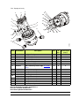
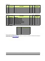
7.3. Body assembly . . . . . . . . . . . . . . . . . . . . . . . . . . . . . . . . . . . . 46
7.3.1. Equipped body . . . . . . . . . . . . . . . . . . . . . . . . . . . . . . . . . . . . . 47
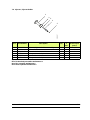
7.4. Injector / injector holder . . . . . . . . . . . . . . . . . . . . . . . . . . . . 49
7.5. Placebo UHT 158 without resistor . . . . . . . . . . . . . . . . . . . . . 50
7.5.1. High voltage connection. . . . . . . . . . . . . . . . . . . . . . . . . . . . . 51
7.6. Robot adapters . . . . . . . . . . . . . . . . . . . . . . . . . . . . . . . . . . . 52
7.6.1. Adapter for Motoman EXP 2050 and 2900 robots. . . . . . . . . 52
7.6.2. Adapter for Fanuc P250 robot. . . . . . . . . . . . . . . . . . . . . . . . . 52
7.6.3. Adapter for Staubli RX 160 robot. . . . . . . . . . . . . . . . . . . . . . . 52
7.6.4. Adapter for Staubli TX 250 robot . . . . . . . . . . . . . . . . . . . . . . . 53
7.6.5. Adapter for ABB IRB 4400 robot. . . . . . . . . . . . . . . . . . . . . . . . 53
8. Option Nanobell II, Gun spraying head version - - - - - - - - - - - - - 54
8.1. Characteristics . . . . . . . . . . . . . . . . . . . . . . . . . . . . . . . . . . . . 54
8.1.1. Dimensions . . . . . . . . . . . . . . . . . . . . . . . . . . . . . . . . . . . . . . . . . 54
8.2. Fluid diagram . . . . . . . . . . . . . . . . . . . . . . . . . . . . . . . . . . . . . 55
8.3. Tools . . . . . . . . . . . . . . . . . . . . . . . . . . . . . . . . . . . . . . . . . . . . 55
8.4. Procedure to transform a Nanobell II bell cup version,
to a Nanobell II Gun version . . . . . . . . . . . . . . . . . . . . . . . . . . . . 56
8.5. Maintenance . . . . . . . . . . . . . . . . . . . . . . . . . . . . . . . . . . . . . 58
8.5.1. Summary table of maintenance operations . . . . . . . . . . . . . 58
8.5.2. Preventive maintenance . . . . . . . . . . . . . . . . . . . . . . . . . . . . . 58
8.5.3. Maintenance corrective . . . . . . . . . . . . . . . . . . . . . . . . . . . . . 59
8.6. Spare parts for the Gun spraying head . . . . . . . . . . . . . . . 61
8.6.1. Head. . . . . . . . . . . . . . . . . . . . . . . . . . . . . . . . . . . . . . . . . . . . . . 61
8.6.2. Equipotential plate . . . . . . . . . . . . . . . . . . . . . . . . . . . . . . . . . . 62

Index revision : C - March 2018 5 7108
1. Health and Safety Instructions
This manual contains links to the following user manuals:
•see RT Nr 7071 for the user manual of bell cups and shaping air assemblies, Hi-Te Technol-
ogy
•see RT Nr 6350 for the user manual of the turbine type ”BTM”.
•see RT Nr 6021 for the user manual of the microvalve.
•see RT Nr 7073 for the user manual of the high voltage unit UHT 287 EEx e.
•see RT Nr 6190 for the microphone.
•see RT Nr 6364 for the user manual of the electric systems,
•see RT Nr 6213 for the user manual of the control module GNM 200.
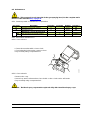
1.1. Configuration of the certified equipment
The whole of these user manuals defines the configuration of the certified equipment.
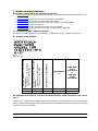
1.2. Marking on the atomizer
P/N : *
Serial number
This equipment is designed in accordance with the Directive ”ATEX” 2014/34/UE and used in
area 2.
** The sign “X” signifies that respecting the safety distance (between the parts of the sprayer
that are under high voltage and the grounded parts) mentioned in this user’s manual, ensures
a safe use of the equipment.
Atomizer Nanobell II - P/N 910016903
Hollow wrist
Equipped body - P/N 910008553
Turbine S12 - P/N 1525802
Atomizer Nanobell II - P/N 910016902
Full wrist
Equipped body - P/N 910008553
Turbine S12 - P/N 1525802
UHT 287 EEx e - P/N 910008371
P/N Nanobell II
(*)
GNM 200A
(220 V)
P/N 1517071
or
GNM 200A
(110V)
P/N 1524481
X X 910016903 X
X X 910016902 X

Index revision : C - March 2018 6 7108
1.3. Precautions for Use
This document contains information that all operators should be aware of and understand
before using the Nanobell. This information highlights situations that could result in serious dam-
age and indicates the precautions that should be taken to avoid them.
WARNING : Before any use of the Nanobell equipment, check that all operators:
• have previously be trained by the compagny SAMES KREMLIN, or by their distributors
registered by them for this purpose.
• have read and understood the user manual and all rules for installation and operation, as
laid out below.
It is the responsibility of the operators’ workshop manager to ensure these two points and it is
also his responsibility to make sure that all operators have read and understood the user
manuals for any peripheral electrical equipment present in the spraying area.
1.4. Warnings
WARNING : Safety may be jeopardized if this equipment is not operated, disassembled and
reassembled in compliance with the instructions given in this manual and in any
European Standard or national safety regulations in force.
WARNING : Equipment performance is only guaranteed if original spare parts distributed by
SAMES KREMLIN are used.

Index revision : C - March 2018 7 7108
WARNING :
This equipment has to be used only within areas designed for spraying with respect to EN 50176,
EN 50177, EN 50223, or with similar ventilation conditions. The equipment has to be used only
within ventilated in order to reduce risks for the health of the operators, fire or explosion. The effi-
ciency of the extraction ventilation system has to be daily checked.
Within explosive atmospheres produced by the spraying process, only appropriate explosion-
proof electrical equipment has to be used.
Before carrying out any cleaning or general work on atomizers in the spraying area, the high
voltage generator must be switched off and the atomizer HV circuit discharged to the ground.
The pressurised coating product or the pressurised air must not be directed towards people or
animals.
Appropriate measures have to be taken to avoid, during periods when the equipment is not
used and/or when the equipment is broken, the presence of potential energy (liquid or air pres-
sure or electric) inside the equipment.
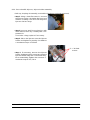
Using individual protection equipment will limit the risks of contact and/or inhalation of toxic
product, gas, vapours, fog or dusts that can be produced while using the equipment. The user
has to follow the coating product manufacturer’s recommendations.
Electrostatic spraying equipment must be serviced regularly in accordance with the informa-
tion and instructions given by SAMES KREMLIN.
It is strictly prohibited to stick adhesive tape on the atomizer body.
Cleaning operations must be carried out either in authorised areas equipped with a
mechanical ventilation system, or using cleaning liquids with a flash point at least 5 °C higher
than room temperature.
Only metal containers can be used for cleaning liquids and they must have a reliable ground
connection
The insulated supply of waterborne paint must be placed in a closed enclosure (by respecting
an insulating distance sufficient). Access must be controlled to the high voltage supply and
equipped with a short-circuiter, which must be placed outside the dangerous areas. This
device must be able to discharge to the ground all the parts at high voltage before being
accessibles. At a minimal level, the installation has to be in accordance with the EN 1953 and
the EN 13849-1.
Inside the booth it is forbidden to use a naked flame, glowing object or a device likely to pro-
duce sparks.
It is also forbidden to store inflammable products, or vessels that have contained them, close
to the booth.
The surrounding area must be kept clear and clean.

Index revision : C - March 2018 8 7108
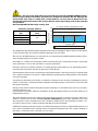
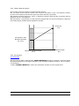
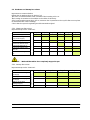
WARNING : The use of very high voltage increases the risk of sparks. SAMES KREMLIN atom-
izers and high-voltage electrostatic generators are designed to minimize this risk. Although the
HV electrode is the only accessible part, a safety distance of X mm (refer to: Board) has to be
maintained between the parts of the sprayer that are under high voltage and all the parts that
are grounded.
Nanobell with UHT 287 EEx e high voltage unit:
Authorised spraying distance
Any installation by isolated system (waterborne) must be equipped with a short-circuiter which
acts in less than two seconds (E < 350 Mj in less than two seconds).
The use of a UHT 287 imposes a connection to a control module GNM 200 whose version of pro-
gram must be higher or equal to V5.63.
In addition, a careful check must be made to ensure that any conducting or semi-conducting
part closer than 2.5 m to the atomizer is correctly grounded.
If it is not, electrical charges capable of causing sparks could build up on it. Operating person-
nel must wear anti-static shoes and gloves to avoid this risk.
All metal parts of the booth and parts to be painted must be correctly grounded. Ground resist-
ance must be less than or equal to 1 MW (minimum measurement voltage 500 V). This must be
checked regularly.
Grounding is mandatory for all the conductive envelops of the electrical equipments and for
all the conductive components within explosive atmospheres by conductive connection with
the ground terminal.
Finally, for the same reasons, the spraying area must have an anti-static floor, such as concrete,
metal duckboard, etc.
It is essential to provide sufficient ventilation in the spraying booths to avoid the build up of
inflammable vapors.
The effectiveness of the overcurrent protection (di/dt) must be checked every day. This check
must be carried out in an area with no explosive atmosphere by placing a ground device near
the electrode of the atomizer when the atomizer is switched on (the operator must be con-
nected to ground): the control module must switch to the fault state.
Additional equipment has to be placed outside the dangerous area and its starting device has
to be servo-controlled to the running mode of the booth aspiration fan. The correct working of
the servo-control has to be checked once a week.
Tension
(kV) Distance
(mm)
010050
60
70 150
200
150
100
50
0050 60 70
DES04891
Distance (mm)
Tension (kV)
”X” safety distance depending on the
voltage
Unauthorised spraying zone

Index revision : C - March 2018 9 7108
A warning board has to be placed in full view close to the sparing area.
An excessive turbine speed can engender major damages on the turbine as well as a loss of
connection bell/turbine; this represents a risk for persons and equipment. The maximum speed
indicated in this user manual must not be exceeded (see § 3.2 page 23).

Index revision : C - March 2018 10 7108
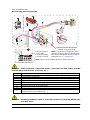
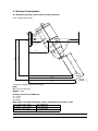
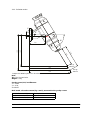
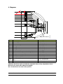
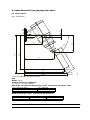
1.4.1. Installation rules
Nanobell using water borne paints.
WARNING : All the conductive components must be connected to the high voltage potential
(metallic fittings of Moduclean, gear pump, etc...).
WARNING : It is strictly prohibited to install an unspecified system not complying with the rules
described above.
Wareborne paints non flamable and not easily flamable
1 Control module GNM 200 (out of the ATEX area)
2 Low voltage connection
3 High voltage unit UHT 287 EEx e
4 High voltage cable connecting UHT 287 / Insulating table and UHT 287 /
5 Supplies of paints and rinsing products insulated to the ground potential
6 Dump return line insulated to the ground potential
7 Short circuiter (out of the ATEX area)
8-
9Safety distance (area around the the atomizer head from the parts with high
voltage outer cover, bellcup etc...)
x
S
A
1
2
5
DES03662
GNM
1
2
3
7
m
m
005
mm
0
05
4
9
6
5
DES06340
9
9
4
S: Rinsing product
A: Air supply
1: Product 1 supply
2: Product 2 supply
Nota: Hoses and low voltage cable pass outside the robot
Nota: A connection to the ground of the
shielding of the connecting cable between
HVU and insulating table at exit of ”cage” is
imperative (see § 7.4.1 page 47)
Protection enclosure if system
isolated out of paint booth

Index revision : C - March 2018 11 7108
1.5. Important Recommendations
1.5.1. Compressed Air Quality
The air must be filtered to a level that will guarantee a long life time and prevent any pollution
during painting.
The filter must be installed as close as possible to the facility. The filter cartridges must be
changed
regularly to ensure that the air is clean.
PTFE tape or glue should not be used between the filter and the bearing as glue residue or
pieces of PTFE may block the small holes of the air bearing and cause turbine failure.
The inside of hoses supplying air to the atomizer and the ports of the quick-disconnect plate
must be clean and free of any traces of paint, solvent or other foreign matter.
The guarantee does not cover faults caused by unclean, unfiltered bearing air resulting from
disregard of the previous recommendations.
WARNING : If the air is not correctly filtered, the bearing may become fouled resulting in a
turbine operating fault. The filtering system used must prevent particles greater
than 5 µm in diameter from reaching the bearing.
WARNING : The guarantee does not cover damage caused by foreign matter such as paint,
solvent or other substances entering the air circuits of the Nanobell.
1.5.2. Product Quality
The paint must be filtered to prevent any damage to the atomizer.
The maximum permissible particle size in the atomizer is 200 µm.
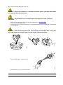
1.5.3. Bearing Safety
The compressed air connection to the air bearing must be made directly to the supply circuit
without the use of an isolating valve.
During operation, the air bearing must be continuously under pressure, otherwise considerable
damage may be caused. A sudden cut in the air supply could destroy the air bearing of the
turbine. Wait until the turbine has stopped completely before cutting off the bearing air.
Procedure for cutting off air to the air bearing:
• Switch off the turbine rotation air supply
• Wait until the turbine has stopped completely (at least 150 s).
• Switch off the bearing air supply.
Running the turbine with bearing air pressure of less than 6 bar at the atomizer inlet can dam-
age the bearing. The standard bearing air pressure is 6 bar at the air control cabinet.
All these pressure values are measured at the atomizer inlet. If the bearing pressure drops below
6 bar at the turbine or atomizer inlet, cut off the air supply to the turbine.
In addition, a 25-liter air reserve should be available so that the turbine brakes gradually if the
main air supply is cut off suddenly.
WARNING : The guarantee does not cover faults that occur if the turbine is operated with in
sufficient bearing air pressure.

Index revision : C - March 2018 12 7108
1.5.4. Locking
Do not atomize the product if the bellcup is not turning at a speed of at least 15000 rpm. At
lower speeds, paint or solvent may enter the turbine, bearing and control circuits. Opening the
head valve, injector
rinsing valve and bellcup exterior rinsing valve must be prohibited when the bellcup is not turn-
ing. Only qualified personnel are authorized to by-pass this locking system for flow rate checks.
WARNING : If the turbine is not already operating, wait, after starting it up, until the bellcup
reaches at least 15000 rpm before opening the head valve. The recommended
minimum waiting time is 2 seconds.
1.5.5. Shaping Air
Do not atomize the product until the shaping air rate is at least 80 Nl/mn (i.e. 0.3 bar at the
atomizer inlet). If it is less, there may be a feedback of atomized product which fouls the outer
cover and the inside surface of the air shroud resulting in application faults.
1.5.6. High Voltage
Disable the high voltage if the Nanobell is not operated for a prolonged period (conveyor shut-
down, no objects to be painted, slack periods, etc.) to prevent ionization of the air.
WARNING : Rinsing cycles (bellcup exterior and injector) must be carried, beforehand switch-
ing off the high voltage power supply.
1.5.7. Maximum Speed
Excessive turbine speed can result in serious damage to the turbine and loss of connection
between the bell cup and turbine, presenting a risk to persons and equipment. The speed must
not exceed 45,000 rpm.
WARNING : The guarantee does not cover damage resulting from a rotation speed greater than
45,000 tr/min.
1.5.8. Vibrations
If the atomizer vibrates more than usual, the cause is generally unbalanced rotating parts.
There may be dry paint deposits on the bell cup or rotor. If any of these situations arise, it is essen-
tial to correct them. Excessive unbalance may damage the turbine resulting in failure to oper-
ate or even loss of the bell cup / turbine connection, presenting a risk for persons and
equipment.
WARNING : The guarantee does not cover damage caused by unbalance of the rotating parts.
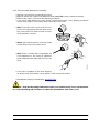
1.5.9. Bell Cup / Turbine Fitting
The bell cup must be correctly fitted on the turbine, a snap must be heard; the two cylinders
must fit on top of each other without any foreign matter between them. If fitting is incorrect, the
connection may be lost and the bell cup thrown out still spinning, presenting a risk for persons
and equipment.

Index revision : C - March 2018 13 7108
1.5.10. O-ring Seals
Use the seals recommended in this manual. For solvent-based products, seals in contact with
the product must be chemically inert seals resistant to swelling or chemical attack. The Nano-
bell is only guaranteed to operate correctly if it is used with seals whose size and material con-
form to this manual.
1.5.11. Ventilation
Do not begin applying paint with the Nanobell before starting up the ventilation system in the
spraying booth. If the ventilation is cut, toxic substances such as organic solvents or ozone may
remain in the spraying booth, resulting in a risk of fire, poisoning or irritation.
1.5.12. Residual pressure
Before all maintenance or repair operations, remove paint and solvent from the atomizer,
switch off the high voltage power supply and cut the paint, solvent and air supplies, then
release residual pressure in each supply system. Residual pressure may lead to component
damage and expose personnel to serious injuries. Paint or solvent dispersion may also lead to
poisoning or irritation.
1.5.13. Safety devices
During installation of the Nanobell, it is important to set up safety devices enabling high voltage
power, paint, solvent and air supplies to be cut immediatly if there is a problem.
• Detection of control system faults
• Detection of high voltage surges linked with the SAMES KREMLIN high voltage module.
• Detection of air pressure drops.
• Detection of ventilation failure.
• Detection of fire
• Detection of human presence.
• Detection of turbine rotation speed faults.
Failure to install safety devices could result in a risk of fire, expose the personnel to serious injury
and damage the equipment.
1.5.14. Restriction on robot wrist movements
In order to optimize the life time of the high voltage cable as well as the supply hoses, it is
recommended to limit the movement of axis 6 to ± 0,5 turns compared with the axis 3.
1.5.15. Mechanical Collision
The guarantee does not cover damage resulting from the operating environment (for example
collision with the robot).
1.5.16. Ambient Temperature
The sprayer is designed to work normally under room temperature between 0°C and + 40°C.
In order to optimise application quality, it is advised to work under room temperature between
+ 15°C and + 28°C.
The storage temperature will never exceed +60°C.
1.5.17. Sound level
The accoustic pressure level, continuous, equivalent, weighted, equals to 59.7 dBA.
Conditions of measurement:
The equipment has been run at its maximum values, the measures have been made from the
operator desk of the paint test booth "API" (closed booth with glass walls) of the Research &
Development laboratory at SAMES KREMLIN Meylan France.
Method of measurement:
The accoustic pressure level, continuous, equivalent, weighted (59.7 dBA) is given in LEQ value,
measured for observation periods of at least 30 seconds.

Index revision : C - March 2018 14 7108
1.5.18. Specific maintenance provisions
The access of the booth, near the atomizer in operation, will have to be proscribed and con-
trolled by safety devices (see § 1.5.13 page 13) which will have to stop the equipment in case
of intrusion of people in the area.
Nevertheless, for maintenance operation, these safety devices will have to be arranged in
order to allow certain operations and checks (only for persons trained and entitled by
SAMES KREMLIN).
The turbine rotation with a bellcup, in all the cases, wil be prohibited with personnel in the area.

Index revision : C - March 2018 15 7108
1.6. Guarantee
Under the guarantee, which applies only to the buyer, SAMES KREMLIN agrees to repair
operating faults resulting from a design fault, materials or manufacture, under the conditions
set out below.
The guarantee claim must define, in writing, the exact nature of the fault concerned.
The SAMES KREMLIN guarantee only covers equipment that has been serviced and
cleaned according to standard procedures and our own instructions, that has been fitted with
parts approved by SAMES KREMLIN or that has not been modified by the customer.
More precisely, the guarantee does not cover damage resulting from:
• the customer's negligence or inattentiveness,
• incorrect use,
• failure to follow the procedure
• use of a control system not designed by SAMES KREMLIN or a SAMES KREMLIN
control system modified by a third party without written permission from an authorized
SAMES KREMLIN technical agent,
• accidents such as: collision with external objects, or similar events,
• flooding, earthquake, fire or similar events,
• inadequately filtered bearing air (solid particles more than 5 µm in diameter),
• inadequately filtered paint and solvent,
• use of seals not complying with SAMES KREMLIN recommendations,
• starting up turbine rotation without minimum bearing air pressure (6 bar),
• exceeding the maximum speed of 45000 rpm under load,
• starting up rotating parts that are unbalanced (dry paint on bellcup, rotor or damaged
bellcups),
• pollution of air circuits by fluids or substances other than air.
SAMES KREMLIN atomizer Nanobell II is covered by a one-year guarantee for use in two 8-
hour shifts under normal operating conditions.
By concession, the guarantee is extended to 10000 hours on the air turbine of the Nanobell II.
The guarantee does not apply to wearing parts such as atomizing bellcups, diaphragms, clips,
seals, etc.
The guarantee will take effect from the date of the first startup or of the provisional acceptance
report.
Under no circumstances, either in the context of this guarantee or in other contexts, will
SAMES KREMLIN be held responsible for physical injury or intangible damage, damage to
brand image and loss of production resulting directly from its products.

Index revision : C - March 2018 16 7108
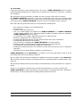
2. Description
2.1. General
Atomizer Nanobell is a robotic rotary atomizer, dedicated according to versions, to the appli-
cation of solvented or waterborned paints, mono paintings or multi-components. It is used in
environments of automatic electrostatic atomization, its design makes of this atomizer
equipment simple, easy to maintain.
Light and compact, it can equip with the small size robots.
Equipped with a magnetic air bearing turbine, the atomizer Nanobell can atomize with a
maximum rotation speed of 45 000 rpm.
Atomizer Nanobell allows to improve the quality of production while making significant savings
of paint.
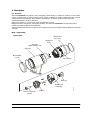
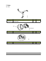
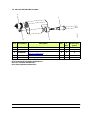
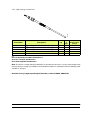
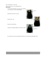
Main components:
DES06336
Turbine
Equipped
body
Support
Bellcup
Placebo
High voltage unit
Shaping air
assembly
Injector / Injector
holder
Nanobell II
cover
Nanobell II
front nut
Microvalve
Hollow wrist

Index revision : C - March 2018 17 7108
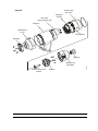
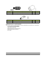
DES06337
Turbine
Equippe
d body
Support
Bellcup
Placebo
High voltage unit
Shaping air
assembly
Injector / Injector
holder
Nanobell II
cover
Adapter
Nanobell II
front nut
Microvalve
Full wrist

Index revision : C - March 2018 18 7108
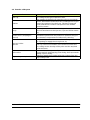
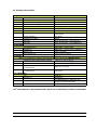
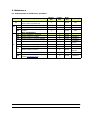
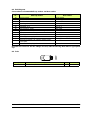
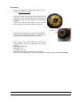
2.2. Function of the parts
Parts Function
Bell cup The bell cup atomizes all types of paint. It is selected
according to the type of product used.
Turbine
The rotation of the bell cup is produced by a pneumatic
motor. Atomization results from the centrifugal forces gen-
erated by rotation of the bell cup. The size of sprayed
paint particles decreases as the speed of the turbine
motor increases.
Body The body houses all the fluid circuits, product, air and sol-
vent microvalves and the injector / injector holder assem-
bly.
Shaping air assembly
(outer cover / shaping air
shroud)
These parts control the size and pattern diameter and
transfer the particles to the parts to be painted. They pro-
tect internal components and allow easy cleaning.
Injector holder
Injector
Keeps the injector in the center of the bell cup. It also has
an opening to supply the microphone air.
The injector is used to regulate the paint flow rate into the
bell cup. The inner diameter of the restrictor is selected
according to the viscosity of the paint and the required
paint thickness
Microvalve Air-controlled, 2-way, normally closed valves used for vari-
ous operations: paint supply, paint rinsing, bell cup exterior
rinsing, injector rinsing
High voltage unit placebo Allows to supply the atomizer with high voltage from the
high voltage unit.

Index revision : C - March 2018 19 7108
3. Technical Characteristics
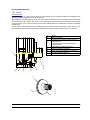
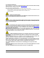
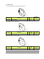
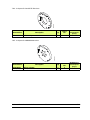
3.1. Dimensions, gravity center and tool center point (mm)
3.1.1. Hollow wrist version
Note:
TCP : Tool Center Point
Weight: 5.1 kg
Gravity center (CG) in millimeters
X = - 21.15
Y = - 0.21
Z = 161.92
Main inertia axis and moments (kg x mm2), measured to the gravity center:
Ix = (-0.49 , 0.00 , 0.87) Px = 16874.33
Iy = (0.97 , -0.01 , 0.49) Py = 43415.41
Iz = (0.01 , 1,00 , 0.00) Pz = 51074.98
232,68
372,05
182,68
328,74
374,34
399,34
0
161,92
21,15
OZ
X
X
DES06338
CG
60°
Output CS: Wrist Payload CG location
TCP@
250mm
TCP@
200mm

Index revision : C - March 2018 20 7108
Inertia moments (kg x mm2), measured to the output C.S:
Ixx = 154787.66 Ixy = -56.66 Ixz = -26799.53
Iyx = -56.66 Iyy = 170943.40 Iyz = -180.07
Izx = -26799.53 Izy = -180.07 Izz = 25372.60
Pagina se încarcă...
Pagina se încarcă...
Pagina se încarcă...
Pagina se încarcă...
Pagina se încarcă...
Pagina se încarcă...
Pagina se încarcă...
Pagina se încarcă...
Pagina se încarcă...
Pagina se încarcă...
Pagina se încarcă...
Pagina se încarcă...
Pagina se încarcă...
Pagina se încarcă...
Pagina se încarcă...
Pagina se încarcă...
Pagina se încarcă...
Pagina se încarcă...
Pagina se încarcă...
Pagina se încarcă...
Pagina se încarcă...
Pagina se încarcă...
Pagina se încarcă...
Pagina se încarcă...
Pagina se încarcă...
Pagina se încarcă...
Pagina se încarcă...
Pagina se încarcă...
Pagina se încarcă...
Pagina se încarcă...
Pagina se încarcă...
Pagina se încarcă...
Pagina se încarcă...
Pagina se încarcă...
Pagina se încarcă...
Pagina se încarcă...
Pagina se încarcă...
Pagina se încarcă...
Pagina se încarcă...
Pagina se încarcă...
Pagina se încarcă...
Pagina se încarcă...
Pagina se încarcă...
-
 1
1
-
 2
2
-
 3
3
-
 4
4
-
 5
5
-
 6
6
-
 7
7
-
 8
8
-
 9
9
-
 10
10
-
 11
11
-
 12
12
-
 13
13
-
 14
14
-
 15
15
-
 16
16
-
 17
17
-
 18
18
-
 19
19
-
 20
20
-
 21
21
-
 22
22
-
 23
23
-
 24
24
-
 25
25
-
 26
26
-
 27
27
-
 28
28
-
 29
29
-
 30
30
-
 31
31
-
 32
32
-
 33
33
-
 34
34
-
 35
35
-
 36
36
-
 37
37
-
 38
38
-
 39
39
-
 40
40
-
 41
41
-
 42
42
-
 43
43
-
 44
44
-
 45
45
-
 46
46
-
 47
47
-
 48
48
-
 49
49
-
 50
50
-
 51
51
-
 52
52
-
 53
53
-
 54
54
-
 55
55
-
 56
56
-
 57
57
-
 58
58
-
 59
59
-
 60
60
-
 61
61
-
 62
62
-
 63
63


în alte limbi
- English: Sames Nanobell II WB User manual
Lucrări înrudite
-
Sames Nanobell II SB Manual de utilizare
-
-
-
-
-
-
-
-
-