Ottobock 6A20=20 Shuttle Lock Manual de utilizare
- Tip
- Manual de utilizare

Gebrauchsanweisung ............................. 4
Instructions for use ................................. 9
Instructions d'utilisation........................... 14
Istruzioni per l’uso .................................. 20
Instrucciones de uso............................... 25
Manual de utilização................................ 31
Gebruiksaanwijzing................................. 36
Bruksanvisning....................................... 41
Brugsanvisning ...................................... 46
Bruksanvisning....................................... 51
Käyttöohje.............................................. 56
Instrukcja użytkowania............................. 61
Használati utasítás .................................. 66
Návod k použití....................................... 71
Instrucţiuni de utilizare............................. 76
Upute za uporabu ................................... 81
Navodila za uporabo ............................... 86
Návod na používanie ............................... 91
Инструкция за употреба......................... 96
Kullanma talimatı .................................... 102
Οδηγίες χρήσης ..................................... 107
Руководство по применению .................. 113
取扱説明書............................................. 119
使用说明书............................................. 124
사용 설명서............................................ 128
6A20=10, 6A20=20

1 2
2

3
3

1 Produktbeschreibung Deutsch
INFORMATION
Datum der letzten Aktualisierung: 2022-03-03
►Lesen Sie dieses Dokument vor Gebrauch des Produkts auf
merksam durch und beachten Sie die Sicherheitshinweise.
►Weisen Sie den Benutzer in den sicheren Gebrauch des Pro
dukts ein.
►Wenden Sie sich an den Hersteller, wenn Sie Fragen zum Pro
dukt haben oder Probleme auftreten.
►Melden Sie jedes schwerwiegende Vorkommnis im Zusammen
hang mit dem Produkt, insbesondere eine Verschlechterung des
Gesundheitszustands, dem Hersteller und der zuständigen Be
hörde Ihres Landes.
►Bewahren Sie dieses Dokument auf.
1.1 Konstruktion und Funktion
Das Shuttle Lock 6A20=10, 6A20=20 dient zur Fixierung eines geeig
neten Liners im Prothesenschaft. Ein Eingussanker wird in den Pro
thesenschaft einlaminiert. Das Shuttle Lock wird anschließend in den
Eingussanker eingeschraubt.
1.2 Kombinationsmöglichkeiten
Diese Prothesenkomponente ist kompatibel mit dem Ottobock Modu
larsystem. Die Funktionalität mit Komponenten anderer Hersteller, die
über kompatible modulare Verbindungselemente verfügen, wurde
nicht getestet.
2 Bestimmungsgemäße Verwendung
2.1 Verwendungszweck
Das Produkt ist ausschließlich für die exoprothetische Versorgung der
unteren Extremität einzusetzen.
2.2 Einsatzgebiet
• Das maximal zugelassene Körpergewicht ist in den Technischen
Daten angegeben (siehe Seite9).
2.3 Umgebungsbedingungen
Zulässige Umgebungsbedingungen
Einsatztemperaturbereich -10 °C bis +60°C
Zulässige relative Luftfeuchtigkeit 0 % bis 90 %, nicht kondensie
rend
Unzulässige Umgebungsbedingungen
Mechanische Vibrationen oder Stöße
Schweiß, Urin, Süßwasser, Salzwasser, Säuren
Staub, Sand, stark hygroskopische Partikel (z.B. Talkum)
2.4 Lebensdauer
Die Nutzungsdauer des Produkts beträgt, abhängig vom Aktivitäts
grad des Patienten, 3 bis 5 Jahre.
3 Sicherheit
3.1 Bedeutung der Warnsymbolik
VORSICHT Warnung vor möglichen Unfall- und Verletzungsge
fahren.
3.2 Allgemeine Sicherheitshinweise
VORSICHT!
Verletzungsgefahr und Gefahr von Produktschäden
►Halten Sie das Einsatzgebiet des Produkts ein und setzen Sie es
keiner Überbeanspruchung aus (siehe Seite4).
►Beachten Sie die Kombinationsmöglichkeiten/Kombinationsaus
schlüsse in den Gebrauchsanweisungen der Produkte.
►Setzen Sie das Produkt keinen unzulässigen Umgebungsbedin
gungen aus.
►Prüfen Sie das Produkt auf Schäden, wenn es unzulässigen Um
gebungsbedingungen ausgesetzt war.
4

►Verwenden Sie das Produkt nicht, wenn es beschädigt oder in ei
nem zweifelhaften Zustand ist. Ergreifen Sie geeignete Maßnah
men: (z.B. Reinigung, Reparatur, Ersatz, Kontrolle durch den
Hersteller oder eine Fachwerkstatt).
►Verwenden Sie das Produkt nicht über die geprüfte Lebensdauer
hinaus, um Verletzungsgefahr und Produktschäden zu verhindern.
►Verwenden Sie das Produkt nur für einen Patienten, um Verlet
zungsgefahr und Produktschäden zu verhindern.
►Arbeiten Sie sorgfältig mit dem Produkt um mechanische Beschä
digung zu verhindern.
►Prüfen Sie das Produkt auf Funktion und Gebrauchsfähigkeit,
wenn Sie Schäden vermuten.
►Verwenden Sie das Produkt nicht, wenn seine Funktion einge
schränkt ist. Ergreifen Sie geeignete Maßnahmen: (z.B. Reini
gung, Reparatur, Ersatz, Kontrolle durch den Hersteller oder eine
Fachwerkstatt)
Anzeichen von Funktionsveränderungen oder -verlust beim Ge
brauch
Funktionsveränderungen können sich z.B. durch ein verändertes
Gangbild, eine veränderte Positionierung der Prothesenkomponenten
zueinander sowie durch Geräuschentwicklung bemerkbar machen.
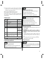
4 Lieferumfang
Menge Benennung Kennzeichen
1 Gebrauchsanweisung –
1 Eingussanker 4R111=N
1 Shuttle Lock Gehäuse –
1 Rasteinheit 6A52
6A20=10:
6Y13=1
1 Pin
6A20=20:
6Y13=2
1 Gipsschutz für Pin 5X440
5
Menge Benennung Kennzeichen
1 Dummyset (1 Halbkugelförmiger Dum
my, 1 Schraubdummy, 1 Gipsschraube)
5X55
Nur für 6A20=20:
4 Gewindestift 506G3
5 Gebrauchsfähigkeit herstellen
VORSICHT
Fehlerhafter Aufbau oder Montage
Verletzungsgefahr durch Schäden an Prothesenkomponenten
►Beachten Sie die Aufbau- und Montagehinweise.
VORSICHT
Fehlerhafte Montage der Schraubverbindungen
Verletzungsgefahr durch Bruch oder Lösen der Schraubverbindun
gen
►Reinigen Sie die Gewinde vor jeder Montage.
►Halten Sie die vorgegebenen Anzugsmomente ein.
►Beachten Sie die Anweisungen zur Länge der Schrauben und
zur Schraubensicherung.
VORSICHT
Falsche Bearbeitung der Ankerarme des Eingussankers
Verletzungsgefahr durch Bruch der Ankerarme
►Schränken Sie nur die Ankerarme der Eingussanker aus Stahl.
►Vermeiden Sie zu starkes und zu häufiges Schränken der Anker
arme.
►Verwenden Sie zum Schränken die Schränkeisen 711S4*.

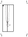
5.1 Schaftherstellung vorbereiten
>Benötigte Materialien: Halbkugelförmiger Dummy, Gipsschrau
be, PVA-Folienschlauch 99B81*
1) HINWEIS! Richten Sie das Shuttle Lock in Stumpflängsach
se aus, um unnötige Belastungen und Verschleiß zu verhin
dern (2307228).
Den halbkugelförmigen Dummy in Stumpflängsachse auf der dis
talen Fläche des Gipsmodells platzieren und mit der Gipsschrau
be locker befestigen.
2) Einen eingeweichten PVA-Folienschlauch über das Gipsmodell
ziehen.
3) Den Prothesenschaft herstellen (siehe Seite6).
5.2 Prothesenschaft herstellen
INFORMATION
Die in diesem Dokument beschriebene Armierung wurde für das
maximale Körpergewicht des Anwenders des Produkts freigegeben.
Jede Veränderung der Armierung liegt in der Verantwortung des Or
thopädietechnikers.
5.2.1 Oberschenkelschaft laminieren
>Benötigte Materialien: Drehmomentschlüssel 710D4, Schränk
eisen 711S4*, Dacron-Filz 616G6, Perlon-Trikotschlauch 623T3,
Carbonfaser-Gewebeband 616B1, Carbonfaser-Gewebe
616G12, Glasfaser-Matte 616G4, Carbonfaser-Flechtschlauch
616G15, PVA-Folienschlauch 99B81, Orthocryl-Laminierharz
80:20 PRO 617H119
1) 1 Lage Dacron-Filz zuschneiden und auf dem Modell platzieren.
2) 2 Lagen Perlon-Trikotschlauch über das Modell ziehen und am
halbkugelförmigen Dummy abbinden.
3) 2 Lagen Carbonfaser-Gewebeband (Breite: 5cm) zirkulär 3cm
unterhalb des Perineums platzieren.
4) Medial und lateral jeweils 1 Lage Carbonfaser-Gewebeband
(Breite: 5cm) vom halbkugelförmigen Dummy bis zum
Schaftrand platzieren.
6
5) Anterior und posterior jeweils 1 Lage Carbonfaser-Gewebe
band (Breite: 5cm) vom halbkugelförmigen Dummy bis zum
Schaftrand platzieren.
6) 4 Streifen (ca. 5cm x 3cm) Glasfaser-Matte auf dem Carbonfa
ser-Gewebeband platzieren, um die Ankerarme zu unterfüttern.
7) 2 Lagen Carbonfaser-Gewebe (z.B. 15cm x 15cm) versetzt
über die Sitzbeinumgreifung platzieren.
8) 2 Lagen Perlon-Trikotschlauch über das Modell ziehen und am
halbkugelförmigen Dummy abbinden.
9) Das ShuttleLock vollständig in den Eingussanker einschrauben
und die Schraube der Gewindeklemmung anziehen (Anzugsmo
ment: 10Nm).
10) Den Eingussanker auf dem halbkugelförmigen Dummy platzieren.
11) Die Ankerarme des Eingussankers in a–p und m–l Richtung aus
richten. Die Gewindeklemmung niemals anterior oder posterior
ausrichten.
12) Optional: Die Ankerarme des Eingussankers mit Schränkeisen
an das Modell anpassen.
13) Das ShuttleLock gegen den Laminierschutz austauschen (siehe
Seite7).
14) Den Klemmbereich des Eingussankers mit Plastaband umwi
ckeln, um den Kontakt mit Laminierharz zu verhindern. So wird ei
ne gleichmäßige Klemmung erreicht.
15) 2 Lagen Carbonfaser-Gewebe (z.B. 15cm x 15cm) versetzt
über den Ankerarmen des Eingussankers platzieren.
16) 2 Lagen Perlon-Trikotschlauch über das Modell ziehen und unter
halb der Zylinderschraube des Eingussankers abbinden..
17) 2 Lagen Carbon-Flechtschlauch über das Modell ziehen und un
terhalb der Zylinderschraube des Eingussankers abbinden..
18) 2 Lagen Perlon-Trikotschlauch über das Modell ziehen und unter
halb der Zylinderschraube des Eingussankers abbinden..
19) Einen eingeweichten PVA-Folienschlauch über das Modell zie
hen.
20) Den Laminiervorgang mit Orthocryl-Laminierharz durchführen.

21) Den Laminierschutz nach dem Aushärten des Laminierharzes ent
fernen.
5.2.2 Unterschenkelschaft laminieren
>Benötigte Materialien: Drehmomentschlüssel 710D4, Zylinder
schraube, Schränkeisen 711S4*, PVA-Folienschlauch 99B81,
Perlon-Trikotschlauch 623T3, Carbonfaser-Gewebeband 616B1,
Glasfaser-Roving 699B1, Carbonfaser-Gewebe 616G12, Glasfa
ser-Matte 616G4, Carbonfaser-Flechtschlauch 616G15, Ortho
cryl-Laminierharz 80:20 PRO 617H119
1) 2 Lagen Perlon-Trikotschlauch über das Modell ziehen und am
halbkugelförmigen Dummy abbinden.
2) 1 Lage Carbonfaser-Gewebeband zirkulär auf Höhe des MPT-
Punkts (Mid Patella Tendon) platzieren.
3) Medial und lateral jeweils 1 Lage Carbonfaser-Gewebeband
(Breite: 5cm) vom halbkugelförmigen Dummy bis zum
Schaftrand platzieren.
4) Anterior und posterior jeweils 1 Lage Carbonfaser-Gewebe
band (Breite: 5cm) vom halbkugelförmigen Dummy bis zum
Schaftrand platzieren.
5) 4 Streifen (ca. 5cm x 3cm) Glasfaser-Matte auf dem Carbonfa
ser-Gewebeband platzieren, um die Ankerarme zu unterfüttern.
6) 2 Lagen Carbonfaser-Gewebe (z.B. 15cm x 15cm) versetzt um
den halbkugelförmigen Dummy am distalen Ende des Modells
platzieren.
7) 2 Lagen Perlon-Trikotschlauch über das Modell ziehen und am
halbkugelförmigen Dummy abbinden.
8) Das ShuttleLock vollständig in den Eingussanker einschrauben
und die Schraube der Gewindeklemmung anziehen (Anzugsmo
ment: 10Nm).
9) Den Eingussanker in Stumpflängsachse auf dem halbkugelförmi
gen Dummy platzieren.
10) Die Ankerarme des Eingussankers in a–p und m–l Richtung aus
richten. Die Gewindeklemmung niemals anterior oder posterior
ausrichten.
7
11) Optional: Die Ankerarme des Eingussankers mit Schränkeisen
an das Modell anpassen.
12) Das ShuttleLock gegen den Laminierschutz austauschen (siehe
Seite7).
13) Den Klemmbereich des Eingussankers mit Plastaband umwi
ckeln, um den Kontakt mit Laminierharz zu verhindern. So wird ei
ne gleichmäßige Klemmung erreicht.
14) Das Glasfaser-Roving durch die Bohrungen der Ankerarme zie
hen und schlaufenförmig hängen lassen. Wenn keine Bohrungen
vorhanden sind, dann das Glasfaser-Roving schlaufenförmig um
die Ankerarme hängen lassen.
15) 3 Lagen Carbonfaser-Gewebe (z.B. 15cm x 15cm) versetzt
über den Ankerarmen des Eingussankers platzieren.
16) 2 Lagen Perlon-Trikotschlauch über das Modell ziehen und unter
halb der Zylinderschraube des Eingussankers abbinden.
17) 1 Stück Carbonfaser-Flechtschlauch zuschneiden (1,3-fache Län
ge des Gipsmodells) und über das Modell ziehen.
18) Den überstehenden Carbonfaser-Flechtschlauch unterhalb der
Zylinderschraube des Eingussankers abbinden und über das
Gipsmodell umschlagen.
19) 2 Lagen Perlon-Trikotschlauch über das Modell ziehen und unter
halb der Zylinderschraube des Eingussankers abbinden.
20) Einen eingeweichten PVA-Folienschlauch überziehen.
21) Den Laminiervorgang mit Orthocryl-Laminierharz durchführen.
22) Den Laminierschutz nach dem Aushärten des Laminierharzes ent
fernen.
5.2.3 Laminierschutz montieren
1) Die Schraube der Gewindeklemmung soweit anziehen, dass sich
das ShuttleLock noch ein- und ausschrauben lässt.
2) Das ShuttleLock aus dem Eingussanker herausschrauben.
3) Den Laminierschutz einschrauben.

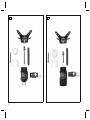
5.3 Endmontage
ShuttleLock montieren
>Benötigte Materialien: Drehmomentschlüssel 710D4, Loctite
241 636K13
1) Das ShuttleLock vollständig in das Gewinde des Eingussankers
einschrauben.
2) Das ShuttleLock zur Ausrichtung maximal3/4Umdrehung aus
dem Gewinde herausschrauben.
3) Die Zylinderschraube der Gewindeklemmung mit Loctite sichern
und mit dem Drehmomentschlüssel anziehen (10Nm).
Rasteinheit einschrauben
>Benötigte Materialien: Drehmomentschlüssel 710D4, Über
gangsteil Vierkant 1/4" innen zu 1/2" außen, Steckschlüsselein
satz
►Die Rasteinheit in das Shuttle Lock einschrauben (Anzugsmo
ment: 20Nm).
6 Gebrauch
VORSICHT
Montage des Pins an einem nicht zugelassenen Liner
Verletzungsgefahr durch Lösen der Schraubverbindung
►Montieren Sie den Pin nur an Linern mit Metallgewinde unter Be
achtung des angegebenen Anzugsmoments.
VORSICHT
Pin wird nicht vollständig in das Lock eingeführt
Verletzungsgefahr durch Verlust der Verbindung zur Prothese
►Führen Sie den Pin gemäß den Handlungsanweisungen in das
Lock ein.
►Prüfen Sie vor jedem Gebrauch der Prothese, ob der Pin im
Lock arretiert ist.
8
Der Liner und das Shuttle Lock werden über den Pin miteinander ver
bunden. Der Pin rastet im Shuttle Lock ein und hält den Liner fest.
Anziehen des Liners
1) Den Pin und den Liner auf Schäden überprüfen.
2) HINWEIS! Den Pin in Stumpflängsachse ausrichten, um
Schäden zu verhindern.
Den Liner aufrollen und am Stumpfende ansetzen.
3) Den Liner faltenfrei, ohne Weichteilverschiebungen oder Luftein
schlüsse, auf den Stumpf abrollen.
4) Den Sitz und die Ausrichtung des Liners überprüfen.
Einsteigen in den Prothesenschaft
1) Mit dem Liner in den Prothesenschaft einsteigen, bis der Pin in
die Öffnung des Shuttle Locks gleitet.
2) Den Pin vollständig in das Shuttle Lock stecken.
3) Vor dem Gebrauch der Prothese prüfen, ob der Pin im Shuttle
Lock arretiert ist.
Aussteigen aus dem Prothesenschaft
►Den seitlichen Taster gedrückt halten und den Stumpf mit Liner
aus dem Prothesenschaft ziehen.
7 Wartung
►Die Prothesenkomponenten nach den ersten 30Tagen Gebrauch
einer Sichtprüfung und Funktionsprüfung unterziehen.
►Die komplette Prothese während der normalen Konsultation auf
Abnutzung überprüfen.
►Jährliche Sicherheitskontrollen durchführen.
8 Rechtliche Hinweise
Alle rechtlichen Bedingungen unterliegen dem jeweiligen Landesrecht
des Verwenderlandes und können dementsprechend variieren.
8.1 Haftung
Der Hersteller haftet, wenn das Produkt gemäß den Beschreibungen
und Anweisungen in diesem Dokument verwendet wird. Für Schäden,

die durch Nichtbeachtung dieses Dokuments, insbesondere durch
unsachgemäße Verwendung oder unerlaubte Veränderung des Pro
dukts verursacht werden, haftet der Hersteller nicht.
8.2 CE-Konformität
Das Produkt erfüllt die Anforderungen der Verordnung (EU) 2017/745
über Medizinprodukte. Die CE-Konformitätserklärung kann auf der
Website des Herstellers heruntergeladen werden.
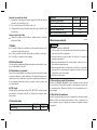
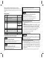
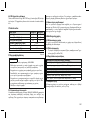
9 Technische Daten
Kennzeichen 6A20=10 6A20=20
Gewicht [g] 425 485
Systemhöhe [mm] 25 79
Einbauhöhe [mm] 43 61
Material (Eingussanker) Stahl
Material (ShuttleLock) Aluminium
Max. Körpergewicht [kg] 125
1 Product description English
INFORMATION
Date of last update: 2022-03-03
►Please read this document carefully before using the product
and observe the safety notices.
►Instruct the user in the safe use of the product.
►Please contact the manufacturer if you have questions about the
product or in case of problems.
►Report each serious incident related to the product to the manu
facturer and to the relevant authority in your country. This is par
ticularly important when there is a decline in the health state.
►Please keep this document for your records.
9
1.1 Construction and Function
The 6A20=10, 6A20=20 shuttle lock serves to secure a suitable liner
in the prosthetic socket. A lamination anchor is laminated into a the
prosthetic socket. Then the shuttle lock is screwed into the lamination
anchor.
1.2 Combination possibilities
This prosthetic component is compatible with Ottobock's system of
modular connectors. Functionality with components of other manufac
turers that have compatible modular connectors has not been tested.
2 Intended use
2.1 Indications for use
The product is intended exclusively for lower limb exoprosthetic fit
tings.
2.2 Area of application
• The maximum approved body weight is specified in the technical
data (see page14).
2.3 Environmental conditions
Allowable environmental conditions
Temperature range for use: -10°Cto +60°C
Allowable relative humidity 0% to 90%, non-condensing
Unallowable environmental conditions
Mechanical vibrations or impacts
Perspiration, urine, fresh water, salt water, acids
Dust, sand, highly hygroscopic particles (e.g. talcum)
2.4 Lifetime
Depending on the patient's level of activity, the service life of the
product is 3 to 5 years.

3 Safety
3.1 Explanation of warning symbols
CAUTION Warning regarding possible risks of accident or
injury.
3.2 General safety instructions
CAUTION!
Risk of injury and risk of product damage
►Comply with the product's field of application and do not expose
it to excessive strain (see page9).
►Note the combination possibilities/combination exclusions in the
instructions for use of the products.
►Do not expose the product to prohibited environmental condi
tions.
►Check the product for damage if it has been exposed to prohib
ited environmental conditions.
►Do not use the product if it is damaged or in a questionable con
dition. Take suitable measures (e.g.cleaning, repair, replace
ment, inspection by the manufacturer or a specialist workshop).
►To avoid the risk of injury and product damage, do not use the
product beyond the tested lifetime.
►To avoid the risk of injury and product damage, only use the
product for a single patient.
►To prevent mechanical damage, use caution when working with
the product.
►If you suspect the product is damaged, check it for proper func
tion and readiness for use.
►Do not use the product if its functionality is restricted. Take suit
able measures (e.g.cleaning, repair, replacement, inspection by
the manufacturer or a specialist workshop).
10
Signs of changes in or loss of functionality during use
Among other factors, changes in functionality can be indicated by an
altered gait pattern, a change in the positioning of the prosthetic com
ponents relative to each other and by the development of noises.
4 Scope of delivery
Quant
ity
Designation Reference
number
1 Instructions for use –
1 Lamination anchor 4R111=N
1 Shuttle lock housing –
1 Ratchet unit 6A52
6A20=10:
6Y13=1
1 Pin
6A20=20:
6Y13=2
1 Plaster protection for pin 5X440
1 Dummy set (1 hemispherical dummy, 1
screw dummy, 1 plaster screw)
5X55
Only for 6A20=20:
4 Set screw 506G3
5 Preparing the product for use
CAUTION
Incorrect alignment or assembly
Risk of injury due to damaged prosthetic components
►Observe the alignment and assembly instructions.
CAUTION
Improper assembly of the screw connections
Risk of injury due to breakage or loosening of the screw connec
tions

►Clean the threads before every installation.
►Apply the specified torque values.
►Follow the instructions regarding the length of the screws and
about how to secure the screws.
CAUTION
Improper processing of the anchor arms of the lamination
anchor
Risk of injury due to breakage of the anchor arms
►Only bend anchor arms of lamination anchors that are made of
steel.
►Avoid bending the anchor arms too strongly or too frequently.
►Use the 711S4* bending irons for bending.
5.1 Preparing for socket fabrication
>Required materials: Hemispherical dummy, plaster screw,
99B81* PVA bag
1) NOTICE! Align the shuttle lock with the longitudinal axis of
the residual limb to prevent unnecessary load and wear
(2307228).
Position the hemispherical dummy on the distal surface of the
plaster model along the longitudinal axis of the residual limb and
loosely secure it with the plaster screw.
2) Pull a soaked PVA bag over the plaster model.
3) Fabricate the prosthetic socket (see page11).
5.2 Fabricating the prosthetic socket
INFORMATION
The layup described in this document was approved for the maxim
um product user body weight. The prosthetist assumes full respons
ibility for any change to the layup.
11
5.2.1 Laminating a transfemoral socket
>Required materials: 710D4 torque wrench, 711S4* bending
iron, 616G6 Dacron felt, 623T3 Perlon stockinette, 616B1 carbon
fibre cloth strap, 616G12 carbon fibre cloth, 616G4 fibreglass
mat, 616G15 carbon fibre woven hose, 99B81 PVA bag,
617H119 Orthocryl lamination resin 80:20 PRO
1) Cut 1 layer of Dacron felt to size and position it on the model.
2) Pull 2 layers of Perlon stockinette over the model and tie it off on
the hemispherical dummy.
3) Position 2 layers of carbon fibre cloth strap (width: 5cm) circu
larly 3cm below the perineum.
4) Medially and laterally, position 1 layer of carbon fibre cloth strap
(width: 5cm) respectively from the hemispherical dummy to the
socket brim.
5) Anterior and posterior, position 1 layer of carbon fibre cloth
strap (width: 5cm) respectively from the hemispherical dummy to
the socket brim.
6) Position 4 strips (approx. 5cm x 3cm) of fibreglass mat on the
carbon fibre cloth strap to line the anchor arms.
7) Position 2 layers of carbon fibre cloth (e.g.15cm x 15cm) offset
over the ischium containment.
8) Pull 2 layers of Perlon stockinette over the model and tie it off on
the hemispherical dummy.
9) Screw the shuttle lock fully into the lamination anchor and tighten
the screw of the threaded clamping (torque value: 10Nm).
10) Position the lamination anchor on the hemispherical dummy.
11) Bring the lamination anchor arms to the correct a-p and m-l posi
tion. Never align the threaded clamping in the anterior or posteri
or direction.
12) Optional: Adapt the anchor arms of the lamination anchor to the
model with a bending iron.
13) Replace the shuttle lock with the lamination dummy (see
page13).

14) Wrap the clamping section of the lamination anchor with plasta
tape to prevent contact with the lamination resin. This ensures
even clamping.
15) Place 2 layers of carbon fibre cloth (e.g.15cm x 15cm) offset
over the lamination anchor arms.
16) Pull 2 layers of Perlon stockinette over the model and tie off below
the cap screw of the lamination anchor.
17) Pull 2 layers of carbon fibre woven hose over the model and tie off
below the cap screw of the lamination anchor.
18) Pull 2 layers of Perlon stockinette over the model and tie off below
the cap screw of the lamination anchor.
19) Pull a soaked PVA bag over the model.
20) Complete the lamination process with Orthocryl lamination resin.
21) After the lamination resin has cured, remove the lamination
dummy.
5.2.2 Laminating the transtibial socket
>Required materials: 710D4 torque wrench, cap screw, 711S4*
bending iron, 99B81 PVA bag, 623T3 Perlon stockinette, 616B1
carbon fibre cloth strap, 699B1 fibreglass roving, 616G12 carbon
fibre cloth, 616G4 fibreglass mat, 616G15 carbon fibre woven
hose, 617H119 Orthocryl lamination resin 80:20 PRO
1) Pull 2 layers of Perlon stockinette over the model and tie it off on
the hemispherical dummy.
2) Position 1 layer of carbon fibre cloth strap circularly around at the
height of the MPT (mid-patella-tendon) point.
3) Medially and laterally, position 1 layer of carbon fibre cloth strap
(width: 5cm) respectively from the hemispherical dummy to the
socket brim.
4) Anterior and posterior, position 1 layer of carbon fibre cloth
strap (width: 5cm) respectively from the hemispherical dummy to
the socket brim.
5) Position 4 strips (approx. 5cm x 3cm) of fibreglass mat on the
carbon fibre cloth strap to line the anchor arms.
12
6) Position 2 layers of carbon fibre cloth (e.g.15 cm x 15cm) offset
around the hemispherical dummy on the distal end of the model.
7) Pull 2 layers of Perlon stockinette over the model and tie it off on
the hemispherical dummy.
8) Screw the shuttle lock fully into the lamination anchor and tighten
the screw of the threaded clamping (torque value: 10Nm).
9) Position the lamination anchor in the longitudinal residual limb
axis on the hemispherical dummy.
10) Bring the lamination anchor arms to the correct a-p and m-l posi
tion. Never align the threaded clamping in the anterior or posteri
or direction.
11) Optional: Adapt the anchor arms of the lamination anchor to the
model with a bending iron.
12) Replace the shuttle lock with the lamination dummy (see
page13).
13) Wrap the clamping section of the lamination anchor with plasta
tape to prevent contact with the lamination resin. This ensures
even clamping.
14) Pull the fibreglass roving through the holes in the anchor arms
and allow it to hang in a loop. If there are no holes, allow the
fibreglass roving to hang around the anchor arms in a loop.
15) Place 3 layers of carbon fibre cloth (e.g.15cm x 15cm) offset
over the lamination anchor arms.
16) Pull 2 layers of Perlon stockinette over the model and tie off below
the cap screw of the lamination anchor.
17) Cut 1 piece of carbon fibre woven hose to size (1.3 times the
length of the plaster model) and pull it over the model.
18) Tie off the excess carbon fibre woven hose below the cap screw
of the lamination anchor and pull it over the plaster model.
19) Pull 2 layers of Perlon stockinette over the model and tie off below
the cap screw of the lamination anchor.
20) Pull on a soaked PVA bag.
21) Complete the lamination process with Orthocryl lamination resin.

22) After the lamination resin has cured, remove the lamination
dummy.
5.2.3 Install the lamination dummy
1) Tighten the screw of the threaded clamping to a point where the
shuttle lock can still be screwed in and out.
2) Unscrew the shuttle lock from the lamination anchor.
3) Screw in the lamination dummy.
5.3 Final assembly
Installing the shuttle lock
>Required materials: 710D4 torque wrench, 636K13 Loctite® 241
1) Screw the shuttle lock completely into the thread of the lamination
anchor.
2) The shuttle lock may be unscrewed from the thread by no more
than 3/4of a turn to align it.
3) Secure the cap screw of the threaded clamping using Loctite®
and tighten using the torque wrench (10Nm).
Screwing in the ratchet unit
>Required materials: 710D4 torque wrench, attachment for
square drive socket wrench (1/4" inside to 1/2" outside), wrench
socket
►Screw the ratchet unit into the shuttle lock (torque value: 20Nm).
6 Use
CAUTION
Installation of the pin in a liner that is not approved
Risk of injury due to loosening of the screw connection
►Only install the pin in liners with a metal thread and observe the
specified tightening torque.
CAUTION
Pin not fully inserted into the lock
Risk of injury due to loss of connection to the prosthesis
13
►Guide the pin into the lock in accordance with the instructions.
►Always verify that the pin is engaged in the lock before using the
prosthesis.
The liner and shuttle lock are connected to each other with the pin.
The pin engages in the shuttle lock and holds the liner in place.
Putting on the Liner
1) Check the pin and liner for damage.
2) NOTICE! Align the pin with the longitudinal axis of the resid
ual limb to prevent damage.
Roll up the liner and place it on the end of the residual limb.
3) Unroll the liner onto the residual limb so that it has no wrinkles,
without shifting the soft tissue.
4) Check the fit and the alignment of the liner.
Donning the Prosthetic Socket
1) Slide into the prosthetic socket with the liner until the pin slides
into the opening of the shuttle lock.
2) Insert the pin fully into the shuttle lock.
3) Before using the prosthesis, verify that the pin is fully engaged in
the shuttle lock.
Doffing the Prosthetic Socket
►Press and hold the side button and pull the residual limb with the
liner out of the prosthetic socket.
7 Maintenance
►A visual inspection and functional test of the prosthetic compo
nents should be performed after the first 30days of use.
►Inspect the entire prosthesis for wear during normal consulta
tions.
►Conduct annual safety inspections.
8 Legal information
All legal conditions are subject to the respective national laws of the
country of use and may vary accordingly.

8.1 Liability
The manufacturer will only assume liability if the product is used in
accordance with the descriptions and instructions provided in this
document. The manufacturer will not assume liability for damage
caused by disregarding the information in this document, particularly
due to improper use or unauthorised modification of the product.
8.2 CE conformity
The product meets the requirements of Regulation (EU) 2017/745 on
medical devices. The CE declaration of conformity can be down
loaded from the manufacturer's website.
9 Technical data
Reference number 6A20=10 6A20=20
Weight [g] 425 485
System height [mm] 25 79
Build height [mm] 43 61
Material (lamination anchor) Steel
Material (shuttle lock) Aluminium
Max. body weight [kg] 125
1 Description du produit Français
INFORMATION
Date de la dernière mise à jour: 2022-03-03
►Veuillez lire attentivement l’intégralité de ce document avant
d’utiliser le produit ainsi que respecter les consignes de sécuri
té.
►Apprenez à l’utilisateur comment utiliser son produit en toute sé
curité.
►Adressez-vous au fabricant si vous avez des questions concer
nant le produit ou en cas de problèmes.
14
►Signalez tout incident grave survenu en rapport avec le produit,
notamment une aggravation de l’état de santé, au fabricant et à
l’autorité compétente de votre pays.
►Conservez ce document.
1.1 Conception et fonctionnement
La prise rapide 6A20=10, 6A20=20 permet de fixer un manchon adap
té dans l’emboîture de prothèse. Une ancre à couler se monte par
stratification dans l’emboîture de prothèse. La prise rapide est ensuite
vissée dans l’ancre à couler.
1.2 Combinaisons possibles
Ce composant prothétique est compatible avec le système modulaire
Ottobock. Le fonctionnement avec des composants d’autres fabri
cants disposant de connecteurs modulaires compatibles n’a pas été
testé.
2 Utilisation conforme
2.1 Usage prévu
Le produit est exclusivement destiné à l’appareillage exoprothétique
des membres inférieurs.
2.2 Domaine d’application
• Le poids corporel maximum admissible est indiqué dans le cha
pitre consacré aux caractéristiques techniques (consulter la
page19).
2.3 Conditions d’environnement
Conditions d’environnement autorisées
Plage de température de fonctionnement -10°Cà+60°C
Humidité relative de l’air admise 0%à90%, sans condensation
Conditions d’environnement non autorisées
Vibrations mécaniques ou chocs
Sueur, urine, eau douce, eau salée, acides

Conditions d’environnement non autorisées
Poussières, grains de sable, particules hygroscopiques (talc par
ex.)
2.4 Durée de vie
La durée d’utilisation du produit est de 3 à 5 ans en fonction du ni
veau d’activité du patient.
3 Sécurité
3.1 Signification des symboles de mise en garde
PRUDENCE Mise en garde contre les éventuels risques
d’accidents et de blessures.
3.2 Consignes générales de sécurité
PRUDENCE!
Risque de blessure et risque de détérioration du produit
►Respecter le domaine d’application du produit et ne pas l’exposer
à une sollicitation excessive (consulter la page14).
►Respecter les combinaisons possibles/exclues qui sont indiquées
dans les notices d’utilisation des produits.
►Ne pas exposer le produit à des conditions ambiantes non autori
sées.
►En cas d’exposition à des conditions ambiantes non autorisées,
vérifier que le produit n’a subi aucun dommage.
►Ne pas utiliser le produit s’il est endommagé ou en cas de doute
sur son état. Prendre les mesures nécessaires (p.ex. nettoyage,
réparation, remplacement, contrôle par le fabricant ou un atelier
spécialisé).
►N’utilisez pas le produit au-delà de la durée de vie testée pour
prévenir tout risque de blessure et toute détérioration du produit.
►Utilisez le produit uniquement pour un patient pour prévenir tout
risque de blessure et toute détérioration du produit.
15
►Manipuler le produit avec précaution pour éviter toute dommage
mécanique.
►En cas de doute sur l’état du produit, vérifier qu’il est bien en état
de fonctionner.
►Ne pas utiliser le produit si sa fonctionnalité est limitée. Prendre
les mesures nécessaires (p.ex. nettoyage, réparation, remplace
ment, contrôle par le fabricant ou un atelier spécialisé).
Signes de modification ou de perte de fonctionnalité détectés
lors de l’utilisation
Une modification de la démarche, un changement du positionnement
des composants prothétiques les uns par rapport aux autres ainsi que
l’émission de bruits constituent des exemples de signes qui
confirment des modifications de la fonctionnalité.
4 Contenu de la livraison
Quanti
té
Désignation Référence
1 Instructions d’utilisation –
1 Ancre à couler 4R111=N
1 Corps de la prise rapide –
1 Unité de blocage 6A52
6A20=10:
6Y13=1
1 Plongeur
6A20=20:
6Y13=2
1 Protège-plâtre pour plongeur 5X440
1 Set de gabarits (1gabarit hémisphé
rique, 1gabarit de vissage, 1vis pour
plâtre)
5X55
Uniquement pour 6A20=20:
4 Vis sans tête 506G3

5 Mise en service du produit
PRUDENCE
Alignement ou montage incorrect
Risque de blessure occasionnée par des composants prothétiques
endommagés
►Respectez les consignes relatives à l’alignement et au montage.
PRUDENCE
Montage incorrect des raccords vissés
Risque de blessure provoqué par une rupture ou un desserrage des
raccords vissés
►Nettoyez les filets avant chaque montage.
►Respectez les couples de serrage prescrits.
►Respectez les consignes relatives à la longueur des vis et au blo
cage des vis.
PRUDENCE
Traitement inapproprié des branches de l’ancre à couler
Risque de blessure occasionnée par la rupture des branches de
l’ancre
►Ne pliez que des branches d’ancre à couler en acier.
►Évitez un pliage excessif et trop fréquent des branches
d’ancrage.
►Utilisez les fers à cintrer 711S4* afin de procéder au pliage.
16
5.1 Préparation de la fabrication de l’emboîture
>Matériel et matériaux requis: gabarit hémisphérique, vis pour
plâtre, film tubulaire en PVA 99B81*
1) AVIS! Orientez la prise rapide dans l’axe longitudinal du
moignon afin d’éviter toute charge et toute usure inutiles
(2307228).
Posez le gabarit hémisphérique dans l’axe longitudinal du moi
gnon sur la surface distale du modèle en plâtre et fixez-le sans
serrer avec la vis pour plâtre.
2) Recouvrez le modèle en plâtre d’un film tubulaire en PVA ramolli
par trempage.
3) Fabriquez l’emboîture de prothèse (consulter la page16).
5.2 Fabrication de l’emboîture de prothèse
INFORMATION
L’armature décrite dans ce document est validée pour le poids cor
porel maximal de l’utilisateur du produit. Toute modification de
l’armature engage la responsabilité de l’orthoprothésiste.
5.2.1 Stratification de l’emboîture fémorale
>Matériel et matériaux nécessaires: clé dynamométrique
710D4, fer à cintrer 711S4*, feutre en Dacron 616G6, tricot tubu
laire en perlon 623T3, rouleau en fibres de carbone 616B1, fibres
de carbone 616G12, tapis en fibres de verre 616G4, tubulaire en
fibres de carbone 616G15, film tubulaire en PVA 99B81, résine
de stratification Orthocryl 80/20 PRO 617H119
1) Ajustez une couche de feutre en Dacron et placez-la sur le mo
dèle.
2) Recouvrez le modèle de deux couches de tricot tubulaire en per
lon et liez-les au gabarit hémisphérique.
3) Posez deux couches de rouleau en fibres de carbone (largeur:
5cm) de manière circulaire 3cm au-dessous du périnée.
4) Sur les parties médiale et latérale, posez une couche de rouleau
en fibres de carbone (largeur: 5cm) du gabarit hémisphérique
jusqu’au bord de l’emboîture.

5) Sur les parties antérieure et postérieure, posez une couche de
rouleau en fibres de carbone (largeur: 5cm) du gabarit hémi
sphérique jusqu’au bord de l’emboîture.
6) Placez 4bandes (env. 5cm x 3cm) de tapis en fibres de verre
sur le rouleau en fibres de carbone pour rebaser les branches de
l’ancre.
7) Placez deux couches de fibres de carbone (parex. 15cm x
15cm) sur le maintien circulaire de l’ischion en les décalant l’une
par rapport à l’autre.
8) Recouvrez le modèle de deux couches de tricot tubulaire en per
lon et liez-les au gabarit hémisphérique.
9) Vissez entièrement la prise rapide dans l’ancre à couler et serrez
la vis du dispositif de blocage fileté (couple de serrage: 10Nm).
10) Placez l’ancre à couler sur le gabarit hémisphérique.
11) Orientez les branches de l’ancre à couler dans les sens a–p et
m–l. Veillez à ne jamais orienter le dispositif de blocage fileté du
côté antérieur ou postérieur.
12) Facultatif: ajustez les branches de l’ancre à couler au modèle
avec le fer à cintrer.
13) Remplacez la prise rapide par la protection de stratification
(consulter la page18).
14) Enveloppez la zone de serrage de l’ancre à couler à l’aide de ru
ban plastifié pour prévenir tout contact avec la résine de stratifica
tion. Il est ainsi possible d’obtenir un serrage homogène.
15) Placez deux couches de fibres de carbone (parex. 15cm x
15cm) sur les branches de l’ancre à couler en les décalant l’une
par rapport à l’autre.
16) Recouvrez le modèle de deux couches de tricot tubulaire en per
lon et liez-les au-dessous de la vis à tête cylindrique de l’ancre à
couler.
17) Recouvrez le modèle de deux couches de tubulaire en fibres de
carbone et liez-les au-dessous de la vis à tête cylindrique de
l’ancre à couler.
17
18) Recouvrez le modèle de deux couches de tricot tubulaire en per
lon et liez-les au-dessous de la vis à tête cylindrique de l’ancre à
couler.
19) Passez un film tubulaire en PVA ramolli par trempage sur le mo
dèle.
20) Exécutez la stratification avec de la résine de stratification Ortho
cryl.
21) Retirez la protection de stratification une fois que la résine de
stratification a durci.
5.2.2 Stratification de l’emboîture tibiale
>Matériel et matériaux nécessaires: clé dynamométrique
710D4, vis à tête cylindrique, fer à cintrer 711S4*, film tubulaire
en PVA 99B81, tricot tubulaire en perlon 623T3, rouleau en fibres
de carbone 616B1, stratifil en fibres de verre 699B1, fibres de
carbone 616G12, tapis en fibres de verre 616G4, tubulaire en
fibres de carbone 616G15, résine de stratification Orthocryl
80/20 PRO 617H119
1) Recouvrez le modèle de deux couches de tricot tubulaire en per
lon et liez-les au gabarit hémisphérique.
2) Posez une couche de rouleau en fibres de carbone de manière
circulaire à la hauteur du point MPT (milieu du tendon patellaire).
3) Sur les parties médiale et latérale, posez une couche de rouleau
en fibres de carbone (largeur: 5cm) du gabarit hémisphérique
jusqu’au bord de l’emboîture.
4) Sur les parties antérieure et postérieure, posez une couche de
rouleau en fibres de carbone (largeur: 5cm) du gabarit hémi
sphérique jusqu’au bord de l’emboîture.
5) Placez 4bandes (env. 5cm x 3cm) de tapis en fibres de verre
sur le rouleau en fibres de carbone pour rebaser les branches de
l’ancre.
6) Placez deux couches de fibres de carbone (parex. 15cm x
15cm) à l’extrémité distale du modèle, en les décalant l’une par
rapport à l’autre autour du gabarit hémisphérique.

7) Recouvrez le modèle de deux couches de tricot tubulaire en per
lon et liez-les au gabarit hémisphérique.
8) Vissez entièrement la prise rapide dans l’ancre à couler et serrez
la vis du dispositif de blocage fileté (couple de serrage: 10Nm).
9) Orientez l’ancre à couler dans l’axe longitudinal du moignon et
placez-la sur le gabarit hémisphérique.
10) Orientez les branches de l’ancre à couler dans les sens a–p et
m–l. Veillez à ne jamais orienter le dispositif de blocage fileté du
côté antérieur ou postérieur.
11) Facultatif: ajustez les branches de l’ancre à couler au modèle
avec le fer à cintrer.
12) Remplacez la prise rapide par la protection de stratification
(consulter la page18).
13) Enveloppez la zone de serrage de l’ancre à couler à l’aide de ru
ban plastifié pour prévenir tout contact avec la résine de stratifica
tion. Il est ainsi possible d’obtenir un serrage homogène.
14) Faites passer le stratifil en fibres de verre par les perçages des
branches de l’ancre et laissez-le pendre en formant une boucle.
Si les branches de l’ancre ne présentent pas de perçage, laissez
pendre le stratifil en fibres de verre autour des branches en for
mant une boucle.
15) Placez trois couches de fibres de carbone (parex. 15cm x
15cm) sur les branches de l’ancre à couler en les décalant l’une
par rapport à l’autre.
16) Recouvrez le modèle de deux couches de tricot tubulaire en per
lon et liez-les au-dessous de la vis à tête cylindrique de l’ancre à
couler.
17) Découpez un morceau de tubulaire en fibres de carbone (1,3fois
la longueur du modèle en plâtre).
18) Nouez la partie excédentaire du tubulaire en fibres de carbone
sous la vis cylindrique de l’ancre à couler et rabattez-la sur le mo
dèle en plâtre.
18
19) Recouvrez le modèle de deux couches de tricot tubulaire en per
lon et liez-les au-dessous de la vis à tête cylindrique de l’ancre à
couler.
20) Recouvrez d’un film tubulaire en PVA ramolli par trempage.
21) Exécutez la stratification avec de la résine de stratification Ortho
cryl.
22) Retirez la protection de stratification une fois que la résine de
stratification a durci.
5.2.3 Montage de la protection de stratification
1) Serrez la vis du dispositif de blocage fileté de telle sorte qu’il soit
encore possible de visser et dévisser la prise rapide.
2) Dévissez la prise rapide de l’ancre à couler.
3) Vissez la protection de stratification.
5.3 Montage final
Montage de la prise rapide
>Matériel et matériaux requis: clé dynamométrique 710D4,
Loctite® 241 636K13
1) Vissez entièrement la prise rapide dans le filetage de l’ancre à
couler.
2) Dévissez la prise rapide du filetage pour l’orienter en veillant à ne
pas dépasser 3/4de tour.
3) Bloquez la vis à tête cylindrique du dispositif de blocage fileté
avec la Loctite® et serrez-la avec la clé dynamométrique (10Nm).
Vissage de l’unité de blocage
>Matériel requis: clé dynamométrique 710D4, pièce de transition
1/4" intérieur sur 1/2" extérieur, douille
►Vissez l’unité de blocage dans la prise rapide (couple de ser
rage: 20Nm).

6 Utilisation
PRUDENCE
Montage du plongeur sur un manchon non autorisé
Risque de blessure provoqué par un desserrage de vis
►Montez le plongeur uniquement sur des manchons disposant
d’un filet en métal et en respectant le couple de serrage indiqué
pour le montage.
PRUDENCE
Plongeur non inséré complètement dans la prise rapide
Risque de blessure occasionnée par la perte de connexion à la pro
thèse
►Insérez le plongeur dans la prise rapide en suivant bien les ins
tructions fournies.
►Avant chaque utilisation de la prothèse, vérifiez que le plongeur
est bien bloqué dans la prise rapide.
Le manchon et la prise rapide sont reliés l’un à l’autre par le plon
geur. Le plongeur s’enclenche dans la prise rapide et permet de
maintenir le manchon.
Mise en place du manchon
1) Vérifiez que le plongeur et le manchon ne sont pas endommagés.
2) AVIS! Orientez le plongeur dans l’axe longitudinal du moi
gnon pour éviter tout dommage.
Retroussez le manchon et placez-le au niveau de l’extrémité du
moignon.
3) Déroulez le manchon sur le moignon sans faire de plis ni déplacer
de parties molles et en évitant la formation de poches d’air.
4) Vérifiez que la position et l’orientation du manchon sont cor
rectes.
Mettre en place l’emboîture de la prothèse
1) Enfilez l’emboîture de prothèse sur le manchon jusqu’à ce que le
plongeur glisse dans l’ouverture de la prise rapide.
19
2) Insérez complètement le plongeur dans la prise rapide.
3) Avant d’utiliser la prothèse, vérifiez que le plongeur est bien blo
qué dans la prise rapide.
Retirer l’emboîture de la prothèse
►Maintenez le bouton latéral enfoncé et retirez le moignon et le
manchon de l’emboîture de la prothèse.
7 Maintenance
►Faites examiner (contrôle visuel et contrôle du fonctionnement)
les composants prothétiques après les 30 premiers jours
d’utilisation.
►Contrôlez la présence de traces d’usure sur l’ensemble de la pro
thèse au cours d’une consultation habituelle.
►Effectuez des contrôles de sécurité une fois par an.
8 Informations légales
Toutes les conditions légales sont soumises à la législation nationale
du pays d’utilisation concerné et peuvent donc présenter des varia
tions en conséquence.
8.1 Responsabilité
Le fabricant est responsable si le produit est utilisé conformément aux
descriptions et instructions de ce document. Le fabricant décline
toute responsabilité pour les dommages découlant d’un non-respect
de ce document, notamment d’une utilisation non conforme ou d’une
modification non autorisée du produit.
8.2 Conformité CE
Ce produit répond aux exigences du Règlement (UE) 2017/745 relatif
aux dispositifs médicaux. La déclaration de conformité CE peut être
téléchargée sur le site Internet du fabricant.
9 Caractéristiques techniques
Référence 6A20=10 6A20=20
Poids [g] 425 485

Référence 6A20=10 6A20=20
Hauteur du système [mm] 25 79
Hauteur de montage [mm] 43 61
Matériau (ancre à couler) Acier
Matériau (prise rapide) Aluminium
Poids max. du patient [kg] 125
1 Descrizione del prodotto Italiano
INFORMAZIONE
Data dell'ultimo aggiornamento: 2022-03-03
►Leggere attentamente il presente documento prima di utilizzare il
prodotto e osservare le indicazioni per la sicurezza.
►Istruire l'utente sull'utilizzo sicuro del prodotto.
►Rivolgersi al fabbricante in caso di domande sul prodotto o all'in
sorgere di problemi.
►Segnalare al fabbricante e alle autorità competenti del proprio
paese qualsiasi incidente grave in connessione con il prodotto,
in particolare ogni tipo di deterioramento delle condizioni di salu
te.
►Conservare il presente documento.
1.1 Costruzione e funzionamento
Lo shuttle lock 6A20=10, 6A20=20 serve per fissare un liner adatto
nell'invasatura della protesi. Un attacco di laminazione viene laminato
nell'invasatura protesica. Lo shuttle lock viene poi avvitato nell'attacco
di laminazione.
1.2 Possibilità di combinazione
Questo componente protesico è compatibile con il sistema modulare
Ottobock. Non è stata testata la funzionalità con componenti di altri
produttori che dispongono di elementi di collegamento modulari com
patibili.
20
2 Uso conforme
2.1 Uso previsto
Il prodotto deve essere utilizzato esclusivamente per protesi esosche
letriche di arto inferiore.
2.2 Campo d'impiego
• Il peso corporeo massimo omologato è indicato nei dati tecnici (v.
pagina25).
2.3 Condizioni ambientali
Condizioni ambientali consentite
Intervallo di temperatura -10°C ... +60°C
Umidità relativa ammissibile 0% ... 90%, senza condensa
Condizioni ambientali non consentite
Vibrazioni meccaniche o urti
Sudore, urina, acqua dolce, acqua salmastra, acidi
Polvere, sabbia, particelle igroscopiche (p. es. talco)
2.4 Vita utile
La durata di utilizzo del prodotto è di 3-5 anni a seconda del grado di
attività del paziente.
3 Sicurezza
3.1 Significato dei simboli utilizzati
CAUTELA Avvertenza relativa a possibili pericoli di incidente e
lesioni.
3.2 Indicazioni generali per la sicurezza
CAUTELA!
Pericolo di lesioni e di danni al prodotto
►Rispettare il campo d'impiego del prodotto e non sottoporlo a sol
lecitazioni eccessive (v. pagina20).
Pagina se încarcă...
Pagina se încarcă...
Pagina se încarcă...
Pagina se încarcă...
Pagina se încarcă...
Pagina se încarcă...
Pagina se încarcă...
Pagina se încarcă...
Pagina se încarcă...
Pagina se încarcă...
Pagina se încarcă...
Pagina se încarcă...
Pagina se încarcă...
Pagina se încarcă...
Pagina se încarcă...
Pagina se încarcă...
Pagina se încarcă...
Pagina se încarcă...
Pagina se încarcă...
Pagina se încarcă...
Pagina se încarcă...
Pagina se încarcă...
Pagina se încarcă...
Pagina se încarcă...
Pagina se încarcă...
Pagina se încarcă...
Pagina se încarcă...
Pagina se încarcă...
Pagina se încarcă...
Pagina se încarcă...
Pagina se încarcă...
Pagina se încarcă...
Pagina se încarcă...
Pagina se încarcă...
Pagina se încarcă...
Pagina se încarcă...
Pagina se încarcă...
Pagina se încarcă...
Pagina se încarcă...
Pagina se încarcă...
Pagina se încarcă...
Pagina se încarcă...
Pagina se încarcă...
Pagina se încarcă...
Pagina se încarcă...
Pagina se încarcă...
Pagina se încarcă...
Pagina se încarcă...
Pagina se încarcă...
Pagina se încarcă...
Pagina se încarcă...
Pagina se încarcă...
Pagina se încarcă...
Pagina se încarcă...
Pagina se încarcă...
Pagina se încarcă...
Pagina se încarcă...
Pagina se încarcă...
Pagina se încarcă...
Pagina se încarcă...
Pagina se încarcă...
Pagina se încarcă...
Pagina se încarcă...
Pagina se încarcă...
Pagina se încarcă...
Pagina se încarcă...
Pagina se încarcă...
Pagina se încarcă...
Pagina se încarcă...
Pagina se încarcă...
Pagina se încarcă...
Pagina se încarcă...
Pagina se încarcă...
Pagina se încarcă...
Pagina se încarcă...
Pagina se încarcă...
Pagina se încarcă...
Pagina se încarcă...
Pagina se încarcă...
Pagina se încarcă...
Pagina se încarcă...
Pagina se încarcă...
Pagina se încarcă...
Pagina se încarcă...
Pagina se încarcă...
Pagina se încarcă...
Pagina se încarcă...
Pagina se încarcă...
Pagina se încarcă...
Pagina se încarcă...
Pagina se încarcă...
Pagina se încarcă...
Pagina se încarcă...
Pagina se încarcă...
Pagina se încarcă...
Pagina se încarcă...
Pagina se încarcă...
Pagina se încarcă...
Pagina se încarcă...
Pagina se încarcă...
Pagina se încarcă...
Pagina se încarcă...
Pagina se încarcă...
Pagina se încarcă...
Pagina se încarcă...
Pagina se încarcă...
Pagina se încarcă...
Pagina se încarcă...
Pagina se încarcă...
Pagina se încarcă...
Pagina se încarcă...
Pagina se încarcă...
Pagina se încarcă...
Pagina se încarcă...
Pagina se încarcă...
Pagina se încarcă...
-
 1
1
-
 2
2
-
 3
3
-
 4
4
-
 5
5
-
 6
6
-
 7
7
-
 8
8
-
 9
9
-
 10
10
-
 11
11
-
 12
12
-
 13
13
-
 14
14
-
 15
15
-
 16
16
-
 17
17
-
 18
18
-
 19
19
-
 20
20
-
 21
21
-
 22
22
-
 23
23
-
 24
24
-
 25
25
-
 26
26
-
 27
27
-
 28
28
-
 29
29
-
 30
30
-
 31
31
-
 32
32
-
 33
33
-
 34
34
-
 35
35
-
 36
36
-
 37
37
-
 38
38
-
 39
39
-
 40
40
-
 41
41
-
 42
42
-
 43
43
-
 44
44
-
 45
45
-
 46
46
-
 47
47
-
 48
48
-
 49
49
-
 50
50
-
 51
51
-
 52
52
-
 53
53
-
 54
54
-
 55
55
-
 56
56
-
 57
57
-
 58
58
-
 59
59
-
 60
60
-
 61
61
-
 62
62
-
 63
63
-
 64
64
-
 65
65
-
 66
66
-
 67
67
-
 68
68
-
 69
69
-
 70
70
-
 71
71
-
 72
72
-
 73
73
-
 74
74
-
 75
75
-
 76
76
-
 77
77
-
 78
78
-
 79
79
-
 80
80
-
 81
81
-
 82
82
-
 83
83
-
 84
84
-
 85
85
-
 86
86
-
 87
87
-
 88
88
-
 89
89
-
 90
90
-
 91
91
-
 92
92
-
 93
93
-
 94
94
-
 95
95
-
 96
96
-
 97
97
-
 98
98
-
 99
99
-
 100
100
-
 101
101
-
 102
102
-
 103
103
-
 104
104
-
 105
105
-
 106
106
-
 107
107
-
 108
108
-
 109
109
-
 110
110
-
 111
111
-
 112
112
-
 113
113
-
 114
114
-
 115
115
-
 116
116
-
 117
117
-
 118
118
-
 119
119
-
 120
120
-
 121
121
-
 122
122
-
 123
123
-
 124
124
-
 125
125
-
 126
126
-
 127
127
-
 128
128
-
 129
129
-
 130
130
-
 131
131
-
 132
132
-
 133
133
-
 134
134
-
 135
135
-
 136
136


Ottobock 6A20=20 Shuttle Lock Manual de utilizare
- Tip
- Manual de utilizare
în alte limbi
Lucrări înrudite
-
Ottobock 5R2 Manual de utilizare
-
Ottobock 6A40 Instrucțiuni de utilizare
-
Ottobock 5R1=1 Socket Attachment Block Instrucțiuni de utilizare
-
Ottobock 4R72 Manual de utilizare
-
Ottobock 1C58 Manual de utilizare
-
Ottobock 4R84 Double Adapter Pyramid Instrucțiuni de utilizare
-
-
Ottobock SACH Foot Men Toes Manual de utilizare
-
Ottobock 4R104=60, 4R104=75 Slide Adapter Manual de utilizare
-
Alte documente
-
Otto Bock 5R1-6 Instructions For Use Manual
-
-
-
 UNITED OFFICE ULG 350 A1 Operating Instructions Manual
-
 UNITED OFFICE ULG 350 A1 Operating Instructions Manual
-
Hama 00050023 Manualul proprietarului
-
Allview P8 Life Manual de utilizare
-
Allview V2 Viper i4G Instrucțiuni de utilizare

