Makita DRV150 Manual de utilizare
- Categorie
- Unelte electrice
- Tip
- Manual de utilizare

DRV150
DRV250
EN Cordless Rivet Gun INSTRUCTION MANUAL 4
PL Nitownica Akumulatorowa INSTRUKCJA OBSŁUGI 10
HU Akkumulátoros szegecselő HASZNÁLATI KÉZIKÖNYV 17
SK Bezdrôtová nitovacia pištoľ NÁVOD NA OBSLUHU 23
CS Akumulátorová nýtovací
pistole NÁVOD K OBSLUZE 29
UK Акумуляторний
заклепковий пістолет ІНСТРУКЦІЯ З
ЕКСПЛУАТАЦІЇ 35
RO Pistol de nituit cu acumulator MANUAL DE INSTRUCŢIUNI 42
DE Akku Blindniet Setzgerät BETRIEBSANLEITUNG 48

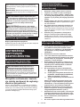
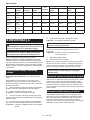
1
2
3
Fig.1
1
2
Fig.2
1
Fig.3
1
Fig.4
12
Fig.5
12
Fig.6
1
2
Fig.7
123
Fig.8
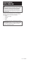
2

1
2
3
1
2
3
Fig.9
1
Fig.10
12
Fig.11
Fig.12
1
2
Fig.13
12
Fig.14
1
2
Fig.15
12
Fig.16
3

4ENGLISH
ENGLISH (Original instructions)
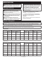
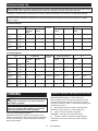
SPECIFICATIONS
Model: DRV150 DRV250
Pulling force 10 kN 20 kN
Stroke 25 mm 30 mm
Overall length 313 mm 323 mm
Rated voltage D.C. 18 V
Net weight 1.9 - 2.2 kg 2.1 - 2.4 kg
•
Due to our continuing program of research and development, the specications herein are subject to change without notice.
•Specications may differ from country to country.
•The weight may differ depending on the attachment(s), including the battery cartridge. The lightest and heavi-
est combination, according to EPTA-Procedure 01/2014, are shown in the table.
Applicable battery cartridge and charger
Battery cartridge BL1815N / BL1820 / BL1820B / BL1830 / BL1830B / BL1840 /
BL1840B / BL1850 / BL1850B / BL1860B
Charger DC18RC / DC18RD / DC18RE / DC18SD / DC18SE / DC18SF /
DC18SH
•
Some of the battery cartridges and chargers listed above may not be available depending on your region of residence.
WARNING: Only use the battery cartridges and chargers listed above. Use of any other battery cartridges
and chargers may cause injury and/or re.
Intended use
The tool is intended for installing blind rivet.
Noise
The typical A-weighted noise level determined accord-
ing to EN62841-1:
Model DRV150
Sound pressure level (LpA) : 75 dB(A)
Uncertainty (K) : 3 dB(A)
Model DRV250
Sound pressure level (LpA) : 74 dB(A)
Uncertainty (K) : 3 dB(A)
The noise level under working may exceed 80 dB (A).
NOTE:
The declared noise emission value(s) has been
measured in accordance with a standard test method
and may be used for comparing one tool with another.
NOTE:
The declared noise emission value(s) may
also be used in a preliminary assessment of exposure.
WARNING: Wear ear protection.
WARNING:
The noise emission during actual
use of the power tool can differ from the declared
value(s) depending on the ways in which the tool is
used especially what kind of workpiece is processed.
WARNING:
Be sure to identify safety measures
to protect the operator that are based on an estima-
tion of exposure in the actual conditions of use (tak-
ing account of all parts of the operating cycle such
as the times when the tool is switched off and when
it is running idle in addition to the trigger time).
Vibration
The vibration total value (tri-axial vector sum) deter-
mined according to EN62841-1:
Model DRV150
Work mode: Installing blind rivet
Vibration emission (ah) : 2.5 m/s2 or less
Uncertainty (K) : 1.5 m/s2
Model DRV250
Work mode: Installing blind rivet
Vibration emission (ah) : 2.5 m/s2 or less
Uncertainty (K) : 1.5 m/s2
NOTE: The declared vibration total value(s) has been
measured in accordance with a standard test method
and may be used for comparing one tool with another.
NOTE: The declared vibration total value(s) may also
be used in a preliminary assessment of exposure.
WARNING: The vibration emission during
actual use of the power tool can differ from the
declared value(s) depending on the ways in which
the tool is used especially what kind of workpiece
is processed.
WARNING: Be sure to identify safety mea-
sures to protect the operator that are based on an
estimation of exposure in the actual conditions of
use (taking account of all parts of the operating
cycle such as the times when the tool is switched
off and when it is running idle in addition to the
trigger time).

5ENGLISH
EC Declaration of Conformity
For European countries only
The EC declaration of conformity is included as Annex A
to this instruction manual.
SAFETY WARNINGS
General power tool safety warnings
WARNING: Read all safety warnings, instruc-
tions, illustrations and specications provided
with this power tool. Failure to follow all instructions
listed below may result in electric shock, re and/or
serious injury.
Save all warnings and instruc-
tions for future reference.
The term "power tool" in the warnings refers to your
mains-operated (corded) power tool or battery-operated
(cordless) power tool.
Cordless rivet gun safety warnings
1. Hold the tool rmly.
2. Keep hands away from moving parts.
3. Always be sure you have a rm footing. Be
sure no one is below when using the tool in
high locations.
4. Be careful not to drop the broken off mandrel
from high locations. Doing so may cause an
accident or injury.
5. Do not scatter the broken off mandrels on the
oor. You may be injured by the sharp end of the
broken off mandrel or by slipping on the mandrel.
6. Do not point the tool at a person or yourself
when operating the tool. The rivet or broken off
mandrel may accidentally ejected, and you may
be injured.
Important safety instructions for
battery cartridge
1. Before using battery cartridge, read all instruc-
tions and cautionary markings on (1) battery
charger, (2) battery, and (3) product using
battery.
2. Do not disassemble battery cartridge.
3. If operating time has become excessively
shorter, stop operating immediately. It may
result in a risk of overheating, possible burns
and even an explosion.
4. If electrolyte gets into your eyes, rinse them
out with clear water and seek medical atten-
tion right away. It may result in loss of your
eyesight.
5. Do not short the battery cartridge:
(1) Do not touch the terminals with any con-
ductive material.
(2) Avoid storing battery cartridge in a con-
tainer with other metal objects such as
nails, coins, etc.
(3) Do not expose battery cartridge to water
or rain.
A battery short can cause a large current
ow, overheating, possible burns and even a
breakdown.
6. Do not store the tool and battery cartridge in
locations where the temperature may reach or
exceed 50 °C (122 °F).
7. Do not incinerate the battery cartridge even if
it is severely damaged or is completely worn
out. The battery cartridge can explode in a re.
8. Be careful not to drop or strike battery.
9. Do not use a damaged battery.
10. The contained lithium-ion batteries are subject
to the Dangerous Goods Legislation require-
ments.
For commercial transports e.g. by third parties,
forwarding agents, special requirement on pack-
aging and labeling must be observed.
For preparation of the item being shipped, consult-
ing an expert for hazardous material is required.
Please also observe possibly more detailed
national regulations.
Tape or mask off open contacts and pack up the
battery in such a manner that it cannot move
around in the packaging.
11. When disposing the battery cartridge, remove
it from the tool and dispose of it in a safe
place. Follow your local regulations relating to
disposal of battery.
12. Use the batteries only with the products
specied by Makita. Installing the batteries to
non-compliant products may result in a re, exces-
sive heat, explosion, or leak of electrolyte.
13. If the tool is not used for a long period of time,
the battery must be removed from the tool.
SAVE THESE INSTRUCTIONS.
CAUTION: Only use genuine Makita batteries.
Use of non-genuine Makita batteries, or batteries that
have been altered, may result in the battery bursting
causing res, personal injury and damage. It will
also void the Makita warranty for the Makita tool and
charger.
Tips for maintaining maximum
battery life
1. Charge the battery cartridge before completely
discharged. Always stop tool operation and
charge the battery cartridge when you notice
less tool power.
2. Never recharge a fully charged battery car-
tridge. Overcharging shortens the battery
service life.
3. Charge the battery cartridge with room tem-
perature at 10 °C - 40 °C (50 °F - 104 °F). Let
a hot battery cartridge cool down before
charging it.
4. Charge the battery cartridge if you do not use
it for a long period (more than six months).

6ENGLISH
FUNCTIONAL DESCRIPTION
CAUTION: Always be sure that the tool is
switched off and the battery cartridge is removed
before adjusting or checking function on the tool.
Installing or removing battery cartridge
CAUTION: Always switch off the tool before
installing or removing of the battery cartridge.
CAUTION: Hold the tool and the battery car-
tridge rmly when installing or removing battery
cartridge. Failure to hold the tool and the battery
cartridge rmly may cause them to slip off your hands
and result in damage to the tool and battery cartridge
and a personal injury.
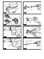
► Fig.1: 1. Red indicator 2. Button 3. Battery cartridge
To remove the battery cartridge, slide it from the tool
while sliding the button on the front of the cartridge.
To install the battery cartridge, align the tongue on the
battery cartridge with the groove in the housing and slip
it into place. Insert it all the way until it locks in place
with a little click. If you can see the red indicator on the
upper side of the button, it is not locked completely.
CAUTION: Always install the battery cartridge
fully until the red indicator cannot be seen. If not,
it may accidentally fall out of the tool, causing injury to
you or someone around you.
CAUTION: Do not install the battery cartridge
forcibly. If the cartridge does not slide in easily, it is
not being inserted correctly.
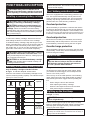
Indicating the remaining battery capacity
Only for battery cartridges with the indicator
► Fig.2: 1. Indicator lamps 2. Check button
Press the check button on the battery cartridge to indi-
cate the remaining battery capacity. The indicator lamps
light up for a few seconds.
Indicator lamps Remaining
capacity
Lighted Off Blinking
75% to 100%
50% to 75%
25% to 50%
0% to 25%
Charge the
battery.
The battery
may have
malfunctioned.
NOTE: Depending on the conditions of use and the
ambient temperature, the indication may differ slightly
from the actual capacity.
Tool / battery protection system
The tool is equipped with a tool/battery protection sys-
tem. This system automatically cuts off power to the
motor to extend tool and battery life. The tool will auto-
matically stop during operation if the tool or battery is
placed under one of the following conditions:
Overload protection
When the battery is operated in a manner that causes
it to draw an abnormally high current, the tool automat-
ically stops without any indication. In this situation, turn
the tool off and stop the application that caused the tool
to become overloaded. Then turn the tool on to restart.
Overheat protection
When the tool or battery is overheated, the tool stops
automatically and the lamp blinks. In this case, let the
tool and battery cool before turning the tool on again.
Overdischarge protection
When the battery capacity is not enough, the tool stops
automatically. In this case, remove the battery from the
tool and charge the battery.
Switch action
WARNING: Before installing the battery car-
tridge into the tool, always check to see that the
switch trigger actuates properly and returns to
the "OFF" position when released.
► Fig.3: 1. Switch trigger
To start the tool, simply pull the switch trigger. When
you release the switch trigger, the tool stops and the
returns to the initial position.
The tool may not in the initial position in the following
cases. Return the tool to the initial position by pulling
and releasing the switch trigger before operating the
tool.
•When using the tool for the rst time.
•After replacing the battery cartridge.
•When the tool stops because of the overload.
•After performing the maintenance.
Lighting up the front lamp
► Fig.4: 1. Lamp
CAUTION: Do not look in the light or see the
source of light directly.
Pull the switch trigger to light up the lamp. The lamp
keeps on lighting while the switch trigger is being pulled.
The lamp goes out approximately 10 seconds after
releasing the switch trigger.
NOTE: Use a dry cloth to wipe the dirt off the lens of
the lamp. Be careful not to scratch the lens of lamp, or
it may lower the illumination.

7ENGLISH
ASSEMBLY
CAUTION: Always be sure that the tool is
switched off and the battery cartridge is removed
before carrying out any work on the tool.
Installing or removing the head
assembly
To remove the head assembly, follow the steps below.
1. Loosen the nut of the head, and then remove the
head.
► Fig.5: 1. Nut 2. Head
2. Loosen the nose piece with a wrench while hold-
ing the head with another wrench.
► Fig.6: 1. Nose piece 2. Head
3. Loosen the jaw case with a wrench while holding
the joint with another wrench.
► Fig.7: 1. Jaw case 2. Joint
4. Remove the jaw pusher, spring, and pipe.
► Fig.8: 1. Jaw pusher 2. Spring 3. Pipe
NOTICE: When installing the jaw pusher, be sure
to attach the spring to the jaw pusher.
To install the head assembly, perform the removal pro-
cedure in reverse. Be sure to tighten the jaw case and
nose piece with two wrenches rmly.
Hook
CAUTION: Always remove the battery when
hanging the tool with the hook.
CAUTION: Never hook the tool at high loca-
tion or on potentially unstable surface.
CAUTION: When hanging the tool with the
hook, hang it carefully. Otherwise, the tool may drop
and cause an injury.
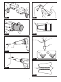
► Fig.9: 1. Groove 2. Hook 3. Screw
The hook is convenient for temporarily hanging the tool.
This can be installed on either side of the tool.
To install the hook, insert it into a groove in the tool
housing on either side and then secure it with a screw.
To remove, loosen the screw and then take it out.
Installing or removing the mandrel
container
NOTICE: Be sure to install the mandrel container
to the tool before operating the tool. If the man-
drel container is not installed to the tool, the tool
will not operate.
To remove the mandrel container, rotate it counter
clockwise. To install the mandrel container, rotate it
clockwise.
► Fig.10: 1. Mandrel container
OPERATION
CAUTION: Keep your hand or face away from
the front part of the tool. The rivet or broken off
mandrel may accidentally ejected, and you may be
injured.
Installing a blind rivet
CAUTION: Before the mandrel container
becomes full, empty it regularly by removing the
mandrel container. Otherwise, the tool may be dam-
aged, and the damaged parts may cause an injury.
CAUTION: When inserting a blind rivet into
the nose piece, be sure to switch off the tool.
Otherwise, you may be injured with the tool tip.
CAUTION: Do not the leave a blind rivet in the
nose piece. If the tool is switched on accidentally, the
blind rivet is ejected and may cause an injury.
NOTICE: After installing a blind rivet, be sure
to eject the broken off mandrel into the mandrel
container by tilting the tool backward before
installing next blind rivet. If the end of the broken
off mandrel sticks out from the nose piece, switch
off the tool and remove the mandrel. Otherwise,
the broken off mandrels may become clogged and
cause a malfunction of the tool.
1. Insert the blind rivet into the nose piece.
► Fig.11: 1. Blind rivet 2. Nose piece
2. Press the tool tip against the workpiece, and then
pull the switch trigger. After the mandrel is broken off,
release the switch trigger.
► Fig.12
Before the mandrel container becomes full, empty it
regularly by removing the mandrel container.

8ENGLISH
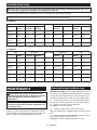
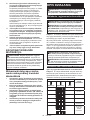
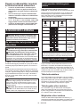
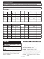
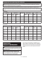
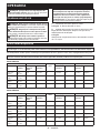
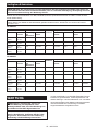
Available blind rivets
NOTICE: Using nose piece, jaw, jaw pusher, or pipe that does not match the mandrel diameter may cause
poor fastening, clogging of the mandrel, or malfunction of the tool.
Refer to the table below for the combination of rivet, nose piece, jaw, jaw pusher, and pipe.
NOTE: Some items in the table may be included in the tool package as standard accessories and some items in
the table are provided as optional accessories. They may differ from country to country.
For DRV150
Rivet Nose piece Mark on jaw Jaw pusher Pipe
Size Diameter of
mandrel Mark on
nose piece Hole
diameter Hole
diameter Color Hole
diameter Color
ø2.4 mm
(3/32″) ø1.4 -
1.6 mm 2.4 ø1.9 mm 4.8 ø1.9 mm Gray ø2.2 mm Silver
ø3.2 mm
(1/8″) ø1.8 -
2.1 mm 3.2 ø2.4 mm 4.8 ø2.5 mm Black ø2.6 mm Black
ø4.0 mm
(5/32″) ø2.2 -
2.6 mm 4.0 ø3.0 mm 4.8 ø3.1 mm Gray None * –
ø4.8 mm
(3/16″)
ø2.6 -
3.2 mm 4.8 ø3.6 mm 4.8 ø3.6 mm Black None * –
*. Pipe is not necessary for operation.
For DRV250
Rivet Nose piece Mark on jaw Jaw pusher Pipe
Size Diameter of
mandrel Mark on
nose piece Hole
diameter Hole
diameter Color Hole
diameter Color
ø2.4 mm
(3/32″) ø1.4 -
1.6 mm 2.4 ø1.9 mm 4.8 ø1.9 mm Gray ø2.2 mm Silver
ø3.2 mm
(1/8″) ø1.8 -
2.1 mm 3.2 ø2.4 mm 4.8 ø2.5 mm Black ø2.6 mm Black
ø4.0 mm
(5/32″) ø2.2 -
2.6 mm 4.0 ø3.0 mm 4.8 ø3.1 mm Gray ø3.4 mm Silver
ø4.8 mm
(3/16″)
ø2.6 -
3.2 mm 4.8 ø3.6 mm 4.8 or 6.4 ø3.6 mm Black ø4.1 mm Black
ø6.0 mm
(1/4″) * ø3.1 -
3.5 mm 6.0 ø4.0 mm 6.4 ø4.0 mm Gray ø4.1 mm Black
ø6.4 mm
(1/4″) * ø3.5 -
3.9 mm 6.4 ø4.4 mm 6.4 ø4.6 mm Black ø4.5 mm Silver
*. Stainless steel rivet is not available.
MAINTENANCE
CAUTION: Always be sure that the tool is
switched off and the battery cartridge is removed
before attempting to perform inspection or
maintenance.
NOTICE: Never use gasoline, benzine, thinner,
alcohol or the like. Discoloration, deformation or
cracks may result.
To maintain product SAFETY and RELIABILITY,
repairs, any other maintenance or adjustment should
be performed by Makita Authorized or Factory Service
Centers, always using Makita replacement parts.
Cleaning the jaws and jaw case
Interval of cleaning: Every 3,000 installations of rivet
If the dust is accumulated, it deteriorates the movement
of jaws and may accelerate wear of jaws and jaw case.
To clean the jaws and jaw case, follow the steps below.
1. Remove the jaw case. For the removal procedure,
refer to the removal instructions for the head assembly.
2. Remove the jaws from the jaw case.
► Fig.13: 1. Jaw case 2. Jaw
3. Clean the jaws and jaw case with a brush.
Remove metal powder clogged between the teeth of the
jaws.
4. Apply molybdenum disulde based grease evenly
to the inner periphery of the jaw case.
► Fig.14: 1. Area to apply grease 2. Jaw case

9ENGLISH
5. Install the jaws to the jaw case.
► Fig.15: 1. Jaw 2. Jaw case
NOTICE: When installing the jaws, be sure to
align the tips of jaws.
6. Install the jaw case. If the grease is adhered to the
tips of the jaws, wipe off the grease with a dry cloth.
► Fig.16: 1. Area where grease should not to be
adhered 2. Jaw
7. Install the head assembly.
8. Wipe off the grease from the jaws.
Insert a rivet into the nose piece, then move it up and
down, and left and right, then remove it from the nose
piece, and then wipe the grease from the rivet with a dry
cloth. Repeat the same procedure twice or 3 times.
NOTICE: If the grease is adhered to the tip
or inside of the jaw, the jaws may slip during
operation.
Replacing the jaws in the jaw case
If the jaws in the jaw case are worn out, replace them
with new ones. To replace the jaws, follow the same
procedure for cleaning the jaws and jaw case. When
installing jaws to the jaw case, install new jaws.
Removing jammed rivet
If the rivet is jammed inside the tool, remove it using a
tool such as pin. If it is difcult to remove the jammed
rivet, replace the jaw pusher or pipe with a new one.
For replacement procedure, refer to the instruction for
installing or removing the head assembly.
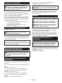
OPTIONAL
ACCESSORIES
CAUTION: These accessories or attachments
are recommended for use with your Makita tool
specied in this manual. The use of any other
accessories or attachments might present a risk of
injury to persons. Only use accessory or attachment
for its stated purpose.
If you need any assistance for more details regard-
ing these accessories, ask your local Makita Service
Center.
•Nose piece
•Jaw pusher
•Jaw
•Pipe
•Grease
•Makita genuine battery and charger
NOTE: Some items in the list may be included in the
tool package as standard accessories. They may
differ from country to country.

10 POLSKI
POLSKI (Instrukcja oryginalna)
DANE TECHNICZNE
Model: DRV150 DRV250
Siła ciągnięcia 10 kN 20 kN
Skok 25 mm 30 mm
Długość całkowita 313 mm 323 mm
Napięcie znamionowe Prąd stały 18 V
Masa netto 1,9–2,2 kg 2,1–2,4 kg
•W związku ze stale prowadzonym przez naszą rmę programem badawczo-rozwojowym niniejsze dane mogą
ulec zmianom bez wcześniejszego powiadomienia.
•Dane techniczne mogą różnić się w zależności od kraju.
•Masa może być różna w zależności od osprzętu, w tym akumulatora. W tabeli przedstawiona jest najlżejsza i
najcięższa konguracja, zgodnie z procedurą EPTA 01/2014.
Kompatybilne akumulatory i ładowarki
Akumulator BL1815N / BL1820 / BL1820B / BL1830 / BL1830B / BL1840 /
BL1840B / BL1850 / BL1850B / BL1860B
Ładowarka DC18RC / DC18RD / DC18RE / DC18SD / DC18SE / DC18SF /
DC18SH
•Pewne z wymienionych powyżej akumulatorów i ładowarek mogą być niedostępne w regionie zamieszkania
użytkownika.
OSTRZEŻENIE: Należy używać wyłącznie akumulatorów i ładowarek wymienionych powyżej.
Używanie innych akumulatorów i ładowarek może stwarzać ryzyko wystąpienia obrażeń ciała lub pożaru.
Przeznaczenie
To narzędzie służy do osadzania nitów jednostronnie
zamykanych.
Hałas
Typowy równoważny poziom dźwięku A określony w
oparciu o normę EN62841-1:
Model DRV150
Poziom ciśnienia akustycznego (LpA): 75 dB(A)
Niepewność (K): 3 dB(A)
Model DRV250
Poziom ciśnienia akustycznego (LpA): 74 dB(A)
Niepewność (K): 3 dB(A)
Poziom hałasu podczas pracy może przekraczać 80 dB (A).
WSKAZÓWKA: Deklarowana wartość emisji hałasu
została zmierzona zgodnie ze standardową metodą
testową i można ją wykorzystać do porównywania
narzędzi.
WSKAZÓWKA: Deklarowaną wartość emisji hałasu
można także wykorzystać we wstępnej ocenie
narażenia.
OSTRZEŻENIE: Nosić ochronniki słuchu.
OSTRZEŻENIE: Poziom hałasu wytwa-
rzanego podczas rzeczywistego użytkowania
elektronarzędzia może się różnić od wartości
deklarowanej w zależności od sposobu użytko-
wania narzędzia, a w szczególności od rodzaju
obrabianego elementu.
OSTRZEŻENIE: W oparciu o szacowane
narażenie w rzeczywistych warunkach użytkowa-
nia należy określić środki bezpieczeństwa w celu
zapewnienia ochrony operatora (uwzględniając
wszystkie elementy cyklu działania, tj. czas, kiedy
narzędzie jest wyłączone i kiedy pracuje na biegu
jałowym, a także czas, kiedy jest włączone).
Drgania
Całkowita wartość poziomu drgań (suma wektorów w 3
osiach) określona zgodnie z normą EN62841-1:
Model DRV150
Tryb pracy: Osadzanie nitów jednostronnie zamykanych
Emisja drgań (ah): 2,5 m/s2 lub mniej
Niepewność (K): 1,5 m/s2
Model DRV250
Tryb pracy: Osadzanie nitów jednostronnie zamykanych
Emisja drgań (ah): 2,5 m/s2 lub mniej
Niepewność (K): 1,5 m/s2

11 POLSKI
WSKAZÓWKA: Deklarowana wartość poziomu
drgań została zmierzona zgodnie ze standardową
metodą testową i można ją wykorzystać do porówny-
wania narzędzi.
WSKAZÓWKA: Deklarowaną wartość poziomu
drgań można także wykorzystać we wstępnej ocenie
narażenia.
OSTRZEŻENIE: Drgania wytwarzane pod-
czas rzeczywistego użytkowania elektronarzędzia
mogą się różnić od wartości deklarowanej w
zależności od sposobu użytkowania narzędzia,
a w szczególności od rodzaju obrabianego
elementu.
OSTRZEŻENIE: W oparciu o szacowane
narażenie w rzeczywistych warunkach użytkowa-
nia należy określić środki bezpieczeństwa w celu
zapewnienia ochrony operatora (uwzględniając
wszystkie elementy cyklu działania, tj. czas, kiedy
narzędzie jest wyłączone i kiedy pracuje na biegu
jałowym, a także czas, kiedy jest włączone).
Deklaracja zgodności WE
Dotyczy tylko krajów europejskich
Deklaracja zgodności WE jest dołączona jako załącznik
A do niniejszej instrukcji obsługi.
OSTRZEŻENIA
DOTYCZĄCE
BEZPIECZEŃSTWA
Ogólne zasady bezpiecznej
eksploatacji elektronarzędzi
OSTRZEŻENIE: Należy zapoznać się z
ostrzeżeniami dotyczącymi bezpieczeństwa,
instrukcjami, ilustracjami i danymi technicz-
nymi dołączonymi do tego elektronarzędzia.
Niezastosowanie się do podanych poniżej instrukcji
może prowadzić do porażenia prądem, pożaru i/lub
poważnych obrażeń ciała.
Wszystkie ostrzeżenia i instruk-
cje należy zachować do wykorzy-
stania w przyszłości.
Pojęcie „elektronarzędzie", występujące w wymienio-
nych tu ostrzeżeniach, odnosi się do elektronarzędzia
zasilanego z sieci elektrycznej (z przewodem zasilają-
cym) lub do elektronarzędzia akumulatorowego (bez
przewodu zasilającego).
Ostrzeżenia dotyczące
bezpieczeństwa dla nitownicy
akumulatorowej
1. Narzędzie należy trzymać mocno i pewnie.
2. Trzymać ręce z dala od części ruchomych.
3. Podczas pracy należy zadbać o stabilne opar-
cie dla nóg. W przypadku pracy na wysokości
upewnić się, że poniżej nie znajdują się żadne
osoby.
4. Należy uważać, aby oderwany trzpień nie spadł
z dużej wysokości. Może to spowodować wypa-
dek lub obrażenia.
5. Nie należy wyrzucać oderwanych trzpieni na
podłogę. Ostra krawędź oderwanego trzpienia
może spowodować obrażenia lub można się pośli-
zgnąć na trzpieniu w wyniku czego również może
dojść do obrażeń.
6. Podczas pracy narzędzia nie należy kiero-
wać go w stronę innych osób lub w swoją
stronę. Nit lub oderwany trzpień może zostać
przypadkowo wyrzucony, co może spowodować
obrażenia.
Ważne zasady bezpieczeństwa
dotyczące akumulatora
1. Przed użyciem akumulatora zapoznać się ze
wszystkimi instrukcjami i znakami ostrze-
gawczymi na (1) ładowarce, (2) akumulatorze
i (3) produkcie, w którym będzie używany
akumulator.
2. Akumulatora nie wolno rozbierać.
3. Jeśli czas działania uległ znacznemu skróce-
niu, należy natychmiast przerwać pracę. Może
bowiem dojść do przegrzania, ewentualnych
poparzeń, a nawet eksplozji.
4. W przypadku przedostania się elektrolitu do
oczu, przemyć je czystą wodą i niezwłocznie
uzyskać pomoc lekarską. Może on bowiem
spowodować utratę wzroku.
5. Nie doprowadzać do zwarcia akumulatora:
(1) Nie dotykać styków materiałami przewo-
dzącymi prąd.
(2) Unikać przechowywania akumulatora w
pojemniku z metalowymi przedmiotami,
takimi jak gwoździe, monety itp.
(3) Chronić akumulator przed deszczem lub
wodą.
Zwarcie prowadzi do przepływu prądu elek-
trycznego o dużym natężeniu i przegrzania
akumulatora, co w konsekwencji może grozić
poparzeniami a nawet awarią urządzenia.
6. Narzędzia i akumulatora nie wolno przecho-
wywać w miejscach, w których temperatura
osiąga bądź przekracza 50°C (122°F).
7. Akumulatorów nie wolno spalać, również tych
poważnie uszkodzonych lub całkowicie zuży-
tych. Akumulator może eksplodować w ogniu.
8. Chronić akumulator przed upadkiem i
uderzeniami.
9. Nie wolno używać uszkodzonego akumulatora.

12 POLSKI
10. Stanowiące wyposażenie akumulatory lito-
wo-jonowe podlegają przepisom dotyczącym
produktów niebezpiecznych.
Na potrzeby transportu komercyjnego, np. świad-
czonego przez rmy trzecie czy spedycyjne,
należy przestrzegać specjalnych wymagań w
zakresie pakowania i oznaczania etykietami.
Przygotowanie produktu do wysyłki wymaga
skonsultowania się ze specjalistą ds. materiałów
niebezpiecznych. Należy także przestrzegać
przepisów krajowych, które mogą być bardziej
szczegółowe.
Zakleić taśmą lub zaślepić otwarte styki akumula-
tora oraz zabezpieczyć go, aby nie mógł się prze-
suwać w opakowaniu.
11. Jeśli zajdzie konieczność utylizacji akumula-
tora, należy wyjąć go z narzędzia i przekazać
w bezpieczne miejsce. Postępować zgodnie z
przepisami lokalnymi dotyczącymi utylizacji
akumulatorów.
12. Używać akumulatorów tylko z produktami
określonymi przez rmę Makita. Zastosowanie
akumulatorów w niezgodnych produktach może
spowodować pożar, przegrzanie, wybuch lub
wyciek elektrolitu.
13. Jeśli narzędzie nie będzie używane przez dłuż-
szy czas, należy wyjąć z niego akumulator.
ZACHOWAĆ NINIEJSZE
INSTRUKCJE.
PRZESTROGA: Używać wyłącznie oryginal-
nych akumulatorów rmy Makita. Używanie nie-
oryginalnych akumulatorów rm innych niż Makita lub
akumulatorów, które zostały zmodykowane, może
spowodować wybuch akumulatora i pożar, obrażenia
ciała oraz zniszczenie mienia. Stanowi to również
naruszenie warunków gwarancji rmy Makita doty-
czących narzędzia i ładowarki.
Wskazówki dotyczące zacho-
wania maksymalnej trwałości
akumulatora
1. Akumulator należy naładować zanim zostanie
do końca rozładowany. Po zauważeniu spadek
mocy narzędzia należy przerwać pracę i nała-
dować akumulator.
2. Nie wolno ładować powtórnie w pełni nałado-
wanego akumulatora. Przeładowanie akumula-
tora skraca jego trwałość.
3. Akumulator należy ładować w temperaturze
pokojowej w przedziale 10–40°C (50–104°F). W
przypadku gorącego akumulatora przed przy-
stąpieniem do ładowania należy poczekać, aż
ostygnie.
4. Akumulatory niklowo-wodorkowe należy nała-
dować po okresie długiego nieużytkowania
(dłuższego niż sześć miesięcy).
OPIS DZIAŁANIA
PRZESTROGA: Przed przystąpieniem do regu-
lacji lub przeglądu narzędzia upewnić się, że jest
ono wyłączone, a akumulator został wyjęty.
Wkładanie i wyjmowanie akumulatora
PRZESTROGA: Przed włożeniem lub wyjęciem
akumulatora należy zawsze wyłączyć narzędzie.
PRZESTROGA: Podczas wkładania lub wyjmo-
wania akumulatora należy mocno trzymać narzę-
dzie i akumulator. W przeciwnym razie mogą się one
wyślizgnąć z rąk, powodując uszkodzenie narzędzia
lub akumulatora i obrażenia ciała.
► Rys.1:
1. Czerwony wskaźnik 2. Przycisk 3. Akumulator
Aby wyjąć akumulator, przesuń przycisk znajdujący się
w przedniej jego części i wysuń akumulator.
Aby włożyć akumulator, wyrównaj występ na akumulato-
rze z rowkiem w obudowie i wsuń go na swoje miejsce.
Akumulator należy wsunąć do oporu, aż się zatrzaśnie na
miejscu, co jest sygnalizowane delikatnym kliknięciem.
Jeśli w górnej części przycisku jest widoczny czerwony
wskaźnik, akumulator nie został całkowicie zatrzaśnięty.
PRZESTROGA:
Akumulator należy włożyć do
końca, tak aby czerwony wskaźnik nie był widoczny. W
przeciwnym razie może przypadkowo wypaść z narzędzia,
powodując obrażenia operatora lub osób postronnych.
PRZESTROGA: Nie wkładać akumulatora na
siłę. Jeśli akumulator nie daje się swobodnie wsunąć,
oznacza to, że został włożony nieprawidłowo.
Wskazanie stanu naładowania akumulatora
Tylko w przypadku akumulatorów ze wskaźnikiem
► Rys.2: 1. Lampki wskaźnika 2. Przycisk kontrolny
Nacisnąć przycisk kontrolny na akumulatorze w celu
wyświetlenia stanu naładowania akumulatora. Lampki
wskaźnika zaświecą się przez kilka sekund.
Lampki wskaźnika Pozostała
energia
akumulatora
Świeci się Wyłączony Miga
75–100%
50–75%
25–50%
0–25%
Naładować
akumulator.
Akumulator
może nie
działać
poprawnie.

13 POLSKI
WSKAZÓWKA: Zależnie od warunków użytkowania
i temperatury otoczenia, wskazywany poziom może
nieznacznie się różnić od rzeczywistego stanu nała-
dowania akumulatora.
Układ zabezpieczenia narzędzia/
akumulatora
Narzędzie jest wyposażone w układ zabezpieczenia
narzędzia/akumulatora. Układ automatycznie odcina
zasilanie silnika w celu wydłużenia trwałości narzędzia
i akumulatora. Narzędzie zostanie automatycznie
zatrzymane podczas pracy w następujących sytuacjach
związanych z narzędziem lub akumulatorem:
Zabezpieczenie przed przeciążeniem
W przypadku użytkowania akumulatora w sposób
powodujący nadmiernie wysoki pobór prądu narzędzie
zostanie automatycznie zatrzymane bez ostrzeżenia. W
takiej sytuacji należy wyłączyć narzędzie i zaprzestać
wykonywania czynności powodującej przeciążenie
narzędzia. Następnie należy włączyć narzędzie w celu
jego ponownego uruchomienia.
Zabezpieczenie przed przegrzaniem
W przypadku przegrzania narzędzia lub akumulatora
narzędzie automatycznie się wyłączy i zacznie migać
lampka. W takiej sytuacji należy odczekać, aż narzę-
dzie ostygnie przed ponownym włączeniem narzędzia.
Zabezpieczenie przed nadmiernym
rozładowaniem
Gdy stan naładowania akumulatora stanie się zbyt
niski, narzędzie zostanie automatycznie zatrzymane.
W takiej sytuacji należy wyjąć akumulator z narzędzia i
naładować go.
Działanie przełącznika
OSTRZEŻENIE: Przed włożeniem akumu-
latora do narzędzia należy zawsze sprawdzić,
czy spust przełącznika działa prawidłowo i
czy powraca do położenia wyłączenia po jego
zwolnieniu.
► Rys.3: 1. Spust przełącznika
Aby uruchomić narzędzie, wystarczy pociągnąć spust
przełącznika. Po zwolnieniu spustu przełącznika narzę-
dzie zatrzyma się i powróci do początkowego położenia.
Poniżej omówiono sytuacje, w których narzędzie może
nie powrócić do położenia początkowego. Przed rozpo-
częciem pracy z użyciem narzędzia należy przywrócić
jego położenie początkowe, ciągnąc i zwalniając spust
przełącznika.
•Jeśli narzędzie jest używane po raz pierwszy.
•Po wymianie akumulatora.
•Jeśli narzędzie zatrzyma się w wyniku
przeciążenia.
•Po przeprowadzeniu konserwacji.
Włączanie lampki czołowej
► Rys.4: 1. Lampka
PRZESTROGA: Nie patrzeć na światło ani
bezpośrednio na źródło światła.
W celu włączenia lampki należy pociągnąć za spust
przełącznika. Lampka świeci, dopóki spust przełącznika
jest naciskany. Lampka wyłącza się po około 10 s od
zwolnienia spustu przełącznika.
WSKAZÓWKA: Aby usunąć zabrudzenia z klosza
lampki, należy użyć suchej szmatki. Uważać, aby nie
zarysować klosza lampki, gdyż może to zmniejszyć
natężenie oświetlenia.
MONTAŻ
PRZESTROGA: Przed przystąpieniem do prac
konserwacyjnych przy narzędziu upewnić się,
że jest ono wyłączone, a akumulator został wyjęty.
Zakładanie i zdejmowanie zespołu
głowicy
Aby zdjąć zespół głowicy, należy wykonać czynności
opisane poniżej.
1. Poluzować nakrętkę głowicy i zdjąć głowicę.
► Rys.5: 1. Nakrętka 2. Głowica
2. Trzymając głowicę kluczem, drugim kluczem
poluzować nosek.
► Rys.6: 1. Nosek 2. Głowica
3. Trzymając łącznik kluczem, drugim kluczem polu-
zować obudowę szczęk.
► Rys.7: 1. Obudowa szczęk 2. Łącznik
4. Wyjąć popychacz szczęk, sprężynę i rurkę.
► Rys.8: 1. Popychacz szczęk 2. Sprężyna 3. Rurka
UWAGA: Przed założeniem popychacza należy
upewnić się, że założono na niego sprężynę.
Aby założyć zespół głowicy, należy wykonać procedurę
zdejmowania w odwrotnej kolejności. Należy pamiętać
o mocnym dokręceniu obudowy szczęk oraz noska
dwoma kluczami.
Zaczep
PRZESTROGA: Przed zawieszeniem narzędzia
za zaczep należy koniecznie wyjąć akumulator.
PRZESTROGA: Nie wolno wieszać narzę-
dzia wysoko lub na potencjalnie niestabilnej
powierzchni.
PRZESTROGA: Podczas wieszania narzędzia
za zaczep należy robić to ostrożnie. W przeciwnym
razie narzędzie może spaść i spowodować obrażenia
ciała.

14 POLSKI
► Rys.9: 1. Rowek 2. Zaczep 3. Wkręt
Zaczep służy do wygodnego, tymczasowego zawie-
szania narzędzia. Można go zamontować z jednej lub z
drugiej strony narzędzia.
Aby zamontować zaczep, należy wsunąć go w rowek
w obudowie narzędzia znajdujący się z obu stron, a
następnie przykręcić go wkrętem. Aby wymontować
zaczep, należy odkręcić wkręt i wyjąć zaczep.
Zakładanie i zdejmowanie
pojemnika na trzpienie
UWAGA: Przed uruchomieniem narzędzia należy
zamontować na nim pojemnik na trzpienie.
Narzędzie nie rozpocznie pracy bez założonego
pojemnika na trzpienie.
Aby zdjąć pojemnik na trzpienie, należy przekręcić go w
lewo. Aby założyć pojemnik na trzpienie, należy prze-
kręcić go w prawo.
► Rys.10: 1. Pojemnik na trzpienie
OBSŁUGA
PRZESTROGA: Nie zbliżać dłoni ani twarzy do
przedniej części narzędzia. Nit lub oderwany trz-
pień może zostać przypadkowo wyrzucony, co może
spowodować obrażenia.
Osadzanie nitów
PRZESTROGA: Pojemnik na trzpienie należy
opróżniać regularnie, zdejmując go zanim stanie
się pełny. W przeciwnym razie narzędzie może ulec
uszkodzeniu, a uszkodzone części mogą spowodo-
wać obrażenia ciała.
PRZESTROGA: Przed włożeniem nitu do noska
należy upewnić się, że narzędzie jest wyłączone.
W przeciwnym razie końcówka narzędzia może spo-
wodować obrażenia.
PRZESTROGA: Nie należy pozostawiać nitu
jednostronnie zamykanego w nosku. W razie
przypadkowego włączenia narzędzia nit zostanie
wyrzucony i może spowodować obrażenia.
UWAGA: Po założeniu nitu jednostronnie zamy-
kanego, a przed założeniem nowego nitu jedno-
stronnie zamykanego należy koniecznie wyrzucić
odłamany trzpień do pojemnika na trzpienie,
odchylając narzędzie do tyłu. Jeśli końcówka
odłamanego trzpienia utknie w nosku, należy
wyłączyć narzędzie i usunąć trzpień. Nieusunięte
odłamane trzpienie mogłyby spowodować zabloko-
wanie i nieprawidłowe działanie narzędzia.
1. Włożyć nit jednostronnie zamykany do noska.
► Rys.11: 1. Nit jednostronnie zamykany 2. Nosek
2. Docisnąć narzędzie do obrabianego elementu, a
następnie pociągnąć za spust przełącznika. Po oderwa-
niu trzpienia zwolnić spust przełącznika.
► Rys.12
Pojemnik na trzpienie należy opróżniać regularnie,
zdejmując go zanim stanie się pełny.
Dostępne nity jednostronnie zamykane
UWAGA: Niedopasowanie noska, szczęk, popychacza szczęk lub rurki do średnicy trzpienia może skutko-
wać słabym mocowaniem, zablokowaniem trzpienia lub nieprawidłowym działaniem narzędzia.
Poniższa tabela przedstawia możliwe kombinacje nitów, nosków, szczęk, popychaczy szczęk i rurek.
WSKAZÓWKA: Niektóre pozycje w tabeli mogą być dołączone do pakietu urządzenia jako akcesoria standar-
dowe, a inne są dostarczane jako akcesoria opcjonalne. Mogą to być różne pozycje, w zależności od kraju.
Model DRV150
Nit Nosek Oznaczenie
na
szczękach
Popychacz szczęk Rurka
Rozmiar Średnica
trzpienia Oznaczenie
na nosku Średnica
otworu Średnica
otworu Kolor Średnica
otworu Kolor
ø2,4 mm
(3/32″) ø1,4–
1,6 mm 2.4 ø1,9 mm 4.8 ø1,9 mm Szary ø2,2 mm Srebrny
ø3,2 mm
(1/8″) ø1,8–
2,1 mm 3.2 ø2,4 mm 4.8 ø2,5 mm Czarny ø2,6 mm Czarny
ø4,0 mm
(5/32″) ø2,2–
2,6 mm 4.0 ø3,0 mm 4.8 ø3,1 mm Szary Brak * –
ø4,8 mm
(3/16″)
ø2,6–
3,2 mm 4.8 ø3,6 mm 4.8 ø3,6 mm Czarny Brak * –
*. Rurka nie jest niezbędna do pracy.

15 POLSKI
Model DRV250
Nit Nosek Oznaczenie
na
szczękach
Popychacz szczęk Rurka
Rozmiar Średnica
trzpienia Oznaczenie
na nosku Średnica
otworu Średnica
otworu Kolor Średnica
otworu Kolor
ø2,4 mm
(3/32″) ø1,4–
1,6 mm 2.4 ø1,9 mm 4.8 ø1,9 mm Szary ø2,2 mm Srebrny
ø3,2 mm
(1/8″) ø1,8–
2,1 mm 3.2 ø2,4 mm 4.8 ø2,5 mm Czarny ø2,6 mm Czarny
ø4,0 mm
(5/32″) ø2,2–
2,6 mm 4.0 ø3,0 mm 4.8 ø3,1 mm Szary ø3,4 mm Srebrny
ø4,8 mm
(3/16″)
ø2,6–
3,2 mm 4.8 ø3,6 mm 4.8 lub 6.4 ø3,6 mm Czarny ø4,1 mm Czarny
ø6,0 mm
(1/4″) * ø3,1–
3,5 mm 6.0 ø4,0 mm 6.4 ø4,0 mm Szary ø4,1 mm Czarny
ø6,4 mm
(1/4″) * ø3,5–
3,9 mm 6.4 ø4,4 mm 6.4 ø4,6 mm Czarny ø4,5 mm Srebrny
*. Nit ze stali nierdzewnej jest niedostępny.
KONSERWACJA
PRZESTROGA: Przed przystąpieniem do prze-
glądu narzędzia lub jego konserwacji upewnić się,
że jest ono wyłączone, a akumulator wyjęty.
UWAGA: Nie stosować benzyny, rozpuszczalni-
ków, alkoholu itp. środków. Mogą one powodo-
wać odbarwienia, odkształcenia lub pęknięcia.
W celu zachowania odpowiedniego poziomu
BEZPIECZEŃSTWA i NIEZAWODNOŚCI produktu
wszelkie naprawy i różnego rodzaju prace konserwa-
cyjne lub regulacje powinny być przeprowadzane przez
autoryzowany lub fabryczny punkt serwisowy narzędzi
Makita, zawsze z użyciem oryginalnych części zamien-
nych Makita.
Czyszczenie szczęk i obudowy
szczęk
Częstotliwość czyszczenia: Co 3 000 założonych
nitów
Nagromadzony kurz utrudnia ruch szczęk i może
przyspieszyć zużycie szczęk oraz ich obudowy. Aby
wyczyścić szczęki i obudowę szczęk, należy wykonać
poniższe czynności.
1. Zdjąć obudowę szczęk. Procedurę zdejmowania
podano w instrukcji zdejmowania zespołu głowicy.
2. Wyjąć szczęki z obudowy szczęk.
► Rys.13: 1. Obudowa szczęk 2. Szczęki
3. Oczyścić szczęki i obudowę szczęk za pomocą
szczotki. Usuń metalowy pył nagromadzony pomiędzy
zębami szczęk.
4. Na wewnętrzną część obudowy szczęk nałożyć
równomiernie smar na bazie dwusiarczku molibdenu.
► Rys.14: 1. Miejsce nakładania smaru 2. Obudowa
szczęk
5. Zamontować szczęki w obudowie szczęk.
► Rys.15: 1. Szczęki 2. Obudowa szczęk
UWAGA: Wkładając szczęki, należy zadbać o to,
aby ich końce były wyrównane.
6. Założyć obudowę szczęk. Jeśli smar przylega
do końców szczęk, należy go powycierać suchą
ściereczką.
► Rys.16: 1. Obszar, w którym nie powinno być
smaru 2. Szczęki
7. Zamontuj zespół głowicy.
8. Powycierać smar ze szczęk.
Włożyć nit do noska, następnie przesunąć go do góry i
do dołu oraz w lewo i w prawo, a następnie wyjąć go z
noska i powycierać smar z nitu, używając suchej ście-
reczki. Procedurę tę należy powtórzyć 2 lub 3 razy.
UWAGA: Jeśli smar przylega do końców lub do
wnętrza szczęk, szczęki mogą się wyślizgnąć
podczas pracy.
Wymiana szczęk w obudowie szczęk
Jeśli szczęki w obudowie szczęk ulegną zużyciu, należy
wymienić je na nowe. Aby wymienić szczęki, należy
wykonać tę samą procedurę, jaka obowiązuje podczas
czyszczenia szczęk i obudowy szczęk. Podczas insta-
lowania szczęk w obudowie szczęk należy zamontować
nowe szczęki.
Usuwanie zakleszczonych nitów
W przypadku zakleszczenia się nitu wewnątrz narzę-
dzia należy wyjąć go odpowiednim narzędziem, takim
jak kołek. Jeśli wyjęcie zakleszczonego nitu sprawia
trudności, należy wymienić popychacz szczęk lub
rurkę na nowe. Procedurę wymiany podano w instrukcji
zakładania i zdejmowania zespołu głowicy.

16 POLSKI
AKCESORIA
OPCJONALNE
PRZESTROGA: Zaleca się stosowanie wymie-
nionych akcesoriów i przystawek razem z narzę-
dziem Makita opisanym w niniejszej instrukcji.
Stosowanie innych akcesoriów lub przystawek
może być przyczyną obrażeń ciała. Akcesoria lub
przystawki należy wykorzystywać tylko zgodnie z ich
przeznaczeniem.
W razie potrzeby wszelkiej pomocy i szczegółowych
informacji na temat niniejszych akcesoriów udzielą
Państwu lokalne punkty serwisowe Makita.
•Nosek
•Popychacz szczęk
•Szczęka
•Rurka
•Smar
•Oryginalny akumulator i ładowarka rmy Makita
WSKAZÓWKA: Niektóre pozycje znajdujące się na
liście mogą być dołączone do pakietu narzędziowego
jako akcesoria standardowe. Mogą to być różne
pozycje, w zależności od kraju.

17 MAGYAR
MAGYAR (Eredeti utasítások)
RÉSZLETES LEÍRÁS
Típus: DRV150 DRV250
Húzóerő 10 kN 20 kN
Löket 25 mm 30 mm
Teljes hossz 313 mm 323 mm
Névleges feszültség 18 V, egyenáram
Nettó tömeg 1,9 - 2,2 kg 2,1 - 2,4 kg
•
Folyamatos kutató- és fejlesztőprogramunk eredményeként az itt felsorolt tulajdonságok gyelmeztetés nélkül megváltozhatnak.
•A tulajdonságok országról országra különbözhetnek.
•A súly a felszerelt tartozékoktól függően változhat, az akkumulátort is beleértve. Az EPTA 01/2014 eljárás
szerint meghatározott legnehezebb, illetve legkönnyebb kombináció a táblázatban látható.
Alkalmazható akkumulátorok és töltők
Akkumulátor BL1815N / BL1820 / BL1820B / BL1830 / BL1830B / BL1840 /
BL1840B / BL1850 / BL1850B / BL1860B
Töltő DC18RC / DC18RD / DC18RE / DC18SD / DC18SE / DC18SF /
DC18SH
•Lakóhelyétől függően előfordulhat, hogy a fent felsorolt akkumulátorok és töltők nem érhetők el.
FIGYELMEZTETÉS: Csak a fentiekben felsorolt akkumulátorokat és töltőket használja. Bármilyen más
akkumulátor vagy töltő használata sérüléseket és/vagy tüzet okozhat.
Rendeltetés
A szerszám vakszegecsek belövésére szolgál.
Zaj
A tipikus A-súlyozású zajszint, a EN62841-1 szerint
meghatározva:
DRV150 típus
Hangnyomásszint (LpA): 75 dB(A)
Bizonytalanság (K): 3 dB(A)
DRV250 típus
Hangnyomásszint (LpA): 74 dB(A)
Bizonytalanság (K): 3 dB(A)
A zajszint a munkavégzés során meghaladhatja a 80 dB (A) értéket.
MEGJEGYZÉS:
A zajkibocsátás értéke a szabványos vizs-
gálati eljárásnak megfelelően lett mérve, és segítségével az
elektromos kéziszerszámok összehasonlíthatók egymással.
MEGJEGYZÉS:
A zajkibocsátás értékének segítségével
előzetesen megbecsülhető a rezgésnek való kitettség mértéke.
FIGYELMEZTETÉS: Viseljen fülvédőt!
FIGYELMEZTETÉS: A szerszám zajkibocsá-
tása egy adott alkalmazásnál eltérhet a megadott
értéktől a használat módjától, különösen a feldol-
gozott munkadarab fajtájától függően.
FIGYELMEZTETÉS:
Határozza meg a kezelő
védelmét szolgáló munkavédelmi lépéseket, melyek az
adott munkafeltételek melletti vibrációs hatás becsült
mértékén alapulnak (gyelembe véve a munkaciklus
elemeit, mint például a gép leállításának és üresjáratá-
nak mennyiségét az elindítások száma mellett).
Vibráció
A vibráció teljes értéke (háromtengelyű vektorösszeg)
az EN62841-1 szerint meghatározva:
DRV150 típus
Üzemmód: Vakszegecsek belővése
Rezgéskibocsátás (ah): 2,5 m/s2 vagy kisebb
Bizonytalanság (K): 1,5 m/s2
DRV250 típus
Üzemmód: Vakszegecsek belővése
Rezgéskibocsátás (ah): 2,5 m/s2 vagy kisebb
Bizonytalanság (K): 1,5 m/s2
MEGJEGYZÉS: A rezgés teljes értéke a szabványos
vizsgálati eljárásnak megfelelően lett mérve, és segít-
ségével az elektromos kéziszerszámok összehason-
líthatók egymással.
MEGJEGYZÉS: A rezgés teljes értékének segítsé-
gével előzetesen megbecsülhető a rezgésnek való
kitettség mértéke.
FIGYELMEZTETÉS: A szerszám rezgéskibo-
csátása egy adott alkalmazásnál eltérhet a meg-
adott értéktől a használat módjától, különösen a
feldolgozott munkadarab fajtájától függően.
FIGYELMEZTETÉS: Határozza meg a kez-
elő védelmét szolgáló munkavédelmi lépéseket,
melyek az adott munkafeltételek melletti vibrációs
hatás becsült mértékén alapulnak (gyelembe
véve a munkaciklus elemeit, mint például a gép
leállításának és üresjáratának mennyiségét az
elindítások száma mellett).

18 MAGYAR
EK Megfelelőségi nyilatkozat
Csak európai országokra vonatkozóan
Az EK-megfelelőségi nyilatkozat az útmutató „A” mel-
lékletében található.
BIZTONSÁGI
FIGYELMEZTETÉS
A szerszámgépekre vonatkozó
általános biztonsági gyelmeztetések
FIGYELMEZTETÉS: Olvassa el a szerszám-
géphez mellékelt összes biztonsági gyelmezte-
tést, utasítást, illusztrációt és a műszaki adatokat.
A következőkben leírt utasítások gyelmen kívül
hagyása elektromos áramütést, tüzet és/vagy súlyos
sérülést eredményezhet.
Őrizzen meg minden gyelmez-
tetést és utasítást a későbbi tájé-
kozódás érdekében.
A gyelmeztetésekben szereplő "szerszámgép" kifejezés
az Ön hálózatról (vezetékes) vagy akkumulátorról (veze-
ték nélküli) működtetett szerszámgépére vonatkozik.
Az akkumulátoros szegecselőre
vonatkozó biztonsági gyelmeztetések
1. Tartsa stabilan a szerszámot.
2. Tartsa távol a kezeit a mozgó alkatrészektől.
3.
Mindig stabil helyzetben dolgozzon. A szerszám
magasban történő használatkor győződjön meg
arról, hogy nem tartózkodik-e valaki odalent.
4. Vigyázzon, ne ejtse le a letört tüskét magas
helyről. Ha így tesz, az balesetet vagy sérülést
okozhat.
5. Ne szórja szét a letört tüskéket a padlón.
A letört tüske éles vége vagy a tüskén való
elcsúszás sérülést okozhat.
6. Működtetés közben ne fordítsa a szerszámot
személyek vagy saját maga felé. A szegecs
vagy a letört tüske véletlenül kilökődhet, és sérü-
lést okozhat.
Fontos biztonsági utasítások az
akkumulátorra vonatkozóan
1. Az akkumulátor használata előtt tanulmá-
nyozza át az akkumulátortöltőn (1), az akkumu-
látoron (2) és az akkumulátorral működtetett
terméken (3) olvasható összes utasítást és
gyelmeztető jelzést.
2. Ne szerelje szét az akkumulátort.
3. Ha a működési idő nagyon lerövidült, azonnal
hagyja abba a használatot. Ez a túlmelegedés,
esetleges égések és akár robbanás veszélyé-
vel is járhat.
4. Ha elektrolit kerül a szemébe, mossa ki azt
tiszta vízzel és azonnal kérjen orvosi segítsé-
get. Ez a látásának elvesztését okozhatja.
5. Ne zárja rövidre az akkumulátort:
(1) Ne érjen az érintkezőkhöz elektromosan
vezető anyagokkal.
(2) Ne tárolja az akkumulátort más fémtár-
gyakkal, mint pl. szegekkel, érmékkel,
stb. egy helyen.
(3) Ne tegye ki az akkumulátort víznek vagy
esőnek.
Az akkumulátor rövidzárlata nagy áramerőssé-
get, túlmelegedést, égéseket, sőt akár meghi-
básodást is okozhat.
6. Ne tárolja a szerszámot vagy az akkumulátort
olyan helyen, ahol a hőmérséklet elérheti vagy
meghaladhatja az 50 °C-ot (122 °F).
7. Ne égesse el az akkumulátort még akkor
sem, ha az komolyan megsérült vagy teljesen
elhasználódott. Az akkumulátor a tűzben
felrobbanhat.
8. Vigyázzon, nehogy leejtse vagy megüsse az
akkumulátort.
9. Ne használjon sérült akkumulátort.
10. A készülékben található lítium-ion akkumuláto-
rokra a veszélyes árukkal kapcsolatos előírá-
sok vonatkoznak.
A termék pl. harmadik felek, fuvarozó cégek stb.
által történő szállítása esetén minden esetben
tartsa szem előtt a csomagoláson és a címkén
található speciális követelményeket.
A termék szállításra történő felkészítése esetén
vegye fel a kapcsolatot egy veszélyes anyagokkal
foglalkozó szakemberrel. Kérjük, hogy az eset-
legesen szigorúbb nemzeti előírásokat is vegye
gyelembe.
Ragassza le a kiálló érintkezőket, illetve oly
módon csomagolja be az akkumulátort, hogy az
ne tudjon elmozdulni a csomagolásban.
11. Az akkumulátor ártalmatlanításakor vegye ki
azt a szerszámból, és ártalmatlanítsa egy biz-
tonságos helyen. Az akkumulátor ártalmatlaní-
tásakor tartsa be a helyi előírásokat.
12. Az akkumulátorokat csak a Makita által meg-
jelölt termékekhez használja. Ha az akkumu-
látorokat azokkal nem kompatibilis termékekbe
helyezi, az tűzhöz, túlmelegedéshez, robbanás-
hoz vagy elektrolitszivárgáshoz vezethet.
13. Ha a szerszám hosszabb ideig nincs hasz-
nálatban, az akkumulátort ki kell venni a
szerszámból.
ŐRIZZE MEG EZEKET AZ
UTASÍTÁSOKAT.
VIGYÁZAT: Csak eredeti Makita akkumuláto-
rokat használjon. A nem eredeti Makita akkumu-
látorok vagy módosított akkumulátorok használata
esetén az akkumulátor felrobbanhat, ami tüzet,
személyi sérülést és anyagi kárt okozhat. A Makita
szerszámra és töltőre vonatkozó Makita garanciát is
érvénytelenítheti.

19 MAGYAR
Tippek az akkumulátor maximá-
lis élettartamának eléréséhez
1. Töltse fel az akkumulátort, mielőtt teljesen
lemerülne. Állítsa le a gépet, és töltse fel az
akkumulátort, ha a gép erejének csökkenését
észleli.
2. Soha ne töltse újra a teljesen feltöltött akku-
mulátort. A túltöltés csökkenti az akkumulátor
élettartamát.
3. Töltse az akkumulátort szobahőmérsékleten,
10 °C - 40 °C (50 °F - 104 °F) között. Töltés előtt
hagyja lehűlni a fölforrósodott akkumulátort.
4. Töltse fel az akkumulátort, ha hosszabb ideje
(több mint hat hónapja) nem használta azt.
A MŰKÖDÉS LEÍRÁSA
VIGYÁZAT: Minden esetben ellenőrizze, hogy
a szerszám ki van kapcsolva és az akkumulátor
eltávolításra került mielőtt beállít vagy ellenőriz
valamilyen funkciót a szerszámon.
Az akkumulátor behelyezése és
eltávolítása
VIGYÁZAT: Mindig kapcsolja ki az eszközt,
mielőtt behelyezi vagy eltávolítja az akkumulátort.
VIGYÁZAT: Az akkumulátor behelyezésekor
vagy eltávolításakor erősen fogja meg a szerszá-
mot és az akkumulátort. Ha nem fogja erősen a
szerszámot és az akkumulátort, azok kicsúszhatnak a
kezei közül, ami a szerszám és az akkumulátor káro-
sodásához, de akár személyi sérüléshez is vezethet.
► Ábra1: 1. Piros jel 2. Gomb 3. Akkumulátor
Az akkumulátoregység kivételéhez nyomja be az akku-
mulátoregység elején található gombot, és húzza le a
gépről.
Az akkumulátor beszereléséhez illessze az akkumulá-
tor nyelvét a burkolaton található vájatba és csúsztassa
a helyére. Egészen addig tolja be, amíg az akkumulátor
egy kis kattanással a helyére nem ugrik. Ha látható a
piros jel a gomb felső oldalán, akkor a gomb nem kat-
tant be teljesen.
VIGYÁZAT: Mindig tolja be teljesen az akku-
mulátort, amíg a piros jel el nem tűnik. Ha ez nem
történik meg, akkor az akkumulátor kieshet a szer-
számból, és Önnek vagy a környezetében másnak
sérülést okozhat.
VIGYÁZAT: Ne erőltesse az akkumulátort behe-
lyezéskor. Ha az akkumulátor nem csúszik be köny-
nyedén, akkor nem megfelelően lett behelyezve.
Az akkumulátor töltöttségének
jelzése
Csak állapotjelzős akkumulátorok esetén
► Ábra2: 1. Jelzőlámpák 2. Check (ellenőrzés) gomb
Nyomja meg az ellenőrzőgombot, hogy az akkumulá-
tortöltöttség-jelző megmutassa a hátralévő akkumu-
látor-kapacitást. Ekkor a töltöttségiszint-jelző lámpák
néhány másodpercre kigyulladnak.
Jelzőlámpák Töltöttségi
szint
Világító
lámpa KI Villogó
lámpa
75%-tól
100%-ig
50%-tól
75%-ig
25%-tól
50%-ig
0%-tól 25%-ig
Töltse fel az
akkumulátort.
Lehetséges,
hogy az
akkumulátor
meghibáso-
dott.
MEGJEGYZÉS: Az adott munkafeltételektől és a kör-
nyezet hőmérsékletétől függően a jelzett töltöttségi
szint némileg eltérhet a tényleges töltöttségi szinttől.
Szerszám-/akkumulátorvédő
rendszer
A gép szerszám-/akkumulátorvédő rendszerrel van
felszerelve. A rendszer automatikusan kikapcsolja a
motor áramellátását, így megnöveli a szerszám és az
akkumulátor élettartamát. A gép használat közben auto-
matikusan leáll, ha a szerszám vagy az akkumulátor a
következő állapotok valamelyikébe kerül:
Túlterhelésvédelem
Ha az akkumulátort úgy használják, hogy az rendelle-
nesen nagy áramot vesz fel, akkor a szerszám minden-
fajta jelzés nélkül leáll. Ilyenkor kapcsolja ki a gépet,
és fejezze be azt a műveletet, amelyik a túlterhelést
okozza. Az újraindításhoz kapcsolja be a gépet.
Túlmelegedés elleni védelem
Ha a szerszám vagy az akkumulátor túlmelegszik,
akkor automatikusan leáll, és a lámpa villogni kezd.
Ilyenkor hagyja lehűlni a szerszámot és az akkumulá-
tort, mielőtt ismét munkához látna.
Mélykisütés elleni védelem
Amikor az akkumulátor kapacitása már alacsony, a
szerszám automatikusan leáll. Ebben az esetben vegye
ki az akkumulátort a szerszámból, majd töltse fel azt.

20 MAGYAR
A kapcsoló használata
FIGYELMEZTETÉS: Mielőtt behelyezi az
akkumulátort a szerszámba, mindig ellenőrizze,
hogy a kapcsológomb hibátlanul működik és
felengedéskor „OFF” állásba áll-e.
► Ábra3: 1. Kapcsológomb
A szerszám bekapcsolásához húzza meg a kapcsoló-
gombot. A kapcsológomb elengedésekor a szerszám
leáll, és visszatér a kezdeti pozícióba.
A következő esetekben előfordulhat, hogy a szerszám
nincs a kezdeti pozícióban. Működtetés előtt állítsa a
szerszámot a kezdeti pozícióba a kapcsológomb meg-
húzásával és elengedésével.
•Ha első alkalommal használja a szerszámot.
•Az akkumulátor cseréje után.
•Ha a szerszám a túlterhelés miatt megáll.
•Karbantartás végzése után.
Az elülső lámpa bekapcsolása
► Ábra4: 1. Lámpa
VIGYÁZAT: Ne tekintsen a fénybe vagy ne
nézze egyenesen a fényforrást.
Húzza meg a kapcsológombot a lámpa bekapcsolásá-
hoz. A lámpa addig világít, amíg a kapcsológomb meg
van húzva. A lámpa a kapcsológomb elengedése után
10 másodperccel alszik ki.
MEGJEGYZÉS: Száraz ruhadarabbal törölje le a
szennyeződést a lámpa lencséjéről. Ügyeljen arra
hogy ne karcolja meg a lámpa lencséjét, ez csökkent-
heti a megvilágítás erősségét.
ÖSSZESZERELÉS
VIGYÁZAT: Minden esetben ellenőrizze, hogy
a szerszám ki van kapcsolva és az akkumulátort
levette, mielőtt bármilyen műveletet végez a
szerszámon.
A fejszerelvény felszerelése és
eltávolítása
A fejszerelvény eltávolításához kövesse az alábbi
lépéseket.
1. Lazítsa meg a fejen az anyát, majd távolítsa el a
fejet.
► Ábra5: 1. Anya 2. Fej
2. Lazítsa meg az orr-részt egy csavarkulccsal,
miközben a fejet egy másik csavarkulccsal tartja.
► Ábra6: 1. Orr-rész 2. Fej
3. Lazítsa meg a pofatartót egy csavarkulccsal,
miközben az összekötőt egy másik csavarkulccsal
tartja.
► Ábra7: 1. Pofatartó 2. Összekötő
4. Távolítsa el a pofatolót, a rugót és a csövet.
► Ábra8: 1. Pofatoló 2. Rugó 3. Cső
MEGJEGYZÉS: A pofatoló beszerelésekor
gondoskodjon róla, hogy csatlakoztatja a rugót a
pofatolóhoz.
A fejszerelvény felszereléséhez hajtsa végre a lesze-
relési eljárást fordított sorrendben. Gondoskodjon róla,
hogy szorosan meghúzza a pofatartót és az orr-részt
két csavarkulccsal.
Akasztó
VIGYÁZAT: Mindig vegye ki az akkumulátort a
szerszámból, amikor felakasztja azt az akasztóval.
VIGYÁZAT: Soha ne akassza a szerszámot
magas helyre vagy nem teljesen stabil felületre.
VIGYÁZAT: Amikor az akasztóval akasztja fel
a szerszámot, legyen óvatos. Máskülönben a szer-
szám leeshet, és sérülést okozhat.
► Ábra9: 1. Horony 2. Akasztó 3. Csavar
Az akasztó a gép ideiglenes felakasztására szolgál.
Felszerelhető a gép mindkét oldalára.
Az akasztó felszereléséhez helyezze azt a gép burko-
latának két oldalán található horonyok valamelyikébe,
majd rögzítse egy csavarral. A leszereléshez csavarja ki
a csavart és vegye le az akasztót.
A tüsketartó felszerelése és
eltávolítása
MEGJEGYZÉS: Gondoskodjon róla, hogy fel-
szerelje a szerszámra a tüsketartót a szerszám
működtetése előtt. Ha a tüsketartó nincs felsze-
relve a szerszámra, a szerszám nem működik.
A tüsketartó eltávolításához forgassa azt az órajárással
ellentétesen. A tüsketartó fellszereléséhez forgassa azt
az órajárás irányába.
► Ábra10: 1. Tüsketartó
Pagina se încarcă...
Pagina se încarcă...
Pagina se încarcă...
Pagina se încarcă...
Pagina se încarcă...
Pagina se încarcă...
Pagina se încarcă...
Pagina se încarcă...
Pagina se încarcă...
Pagina se încarcă...
Pagina se încarcă...
Pagina se încarcă...
Pagina se încarcă...
Pagina se încarcă...
Pagina se încarcă...
Pagina se încarcă...
Pagina se încarcă...
Pagina se încarcă...
Pagina se încarcă...
Pagina se încarcă...
Pagina se încarcă...
Pagina se încarcă...
Pagina se încarcă...
Pagina se încarcă...
Pagina se încarcă...
Pagina se încarcă...
Pagina se încarcă...
Pagina se încarcă...
Pagina se încarcă...
Pagina se încarcă...
Pagina se încarcă...
Pagina se încarcă...
Pagina se încarcă...
Pagina se încarcă...
Pagina se încarcă...
Pagina se încarcă...
-
 1
1
-
 2
2
-
 3
3
-
 4
4
-
 5
5
-
 6
6
-
 7
7
-
 8
8
-
 9
9
-
 10
10
-
 11
11
-
 12
12
-
 13
13
-
 14
14
-
 15
15
-
 16
16
-
 17
17
-
 18
18
-
 19
19
-
 20
20
-
 21
21
-
 22
22
-
 23
23
-
 24
24
-
 25
25
-
 26
26
-
 27
27
-
 28
28
-
 29
29
-
 30
30
-
 31
31
-
 32
32
-
 33
33
-
 34
34
-
 35
35
-
 36
36
-
 37
37
-
 38
38
-
 39
39
-
 40
40
-
 41
41
-
 42
42
-
 43
43
-
 44
44
-
 45
45
-
 46
46
-
 47
47
-
 48
48
-
 49
49
-
 50
50
-
 51
51
-
 52
52
-
 53
53
-
 54
54
-
 55
55
-
 56
56


Makita DRV150 Manual de utilizare
- Categorie
- Unelte electrice
- Tip
- Manual de utilizare
în alte limbi
- slovenčina: Makita DRV150 Používateľská príručka
- polski: Makita DRV150 Instrukcja obsługi