
Issue: 4 (12/2016) – EN
Article number: 84534
USER GUIDE
PVS 100i
Phase Verification System

2
Consultation with Megger
The present system manual has been designed as an operating guide and for reference. It is meant to answer your
questions and solve your problems in as fast and easy a way as possible. Please start with referring to this manual
should any trouble occur.
In doing so, make use of the table of contents and read the relevant paragraph with great attention. Furthermore,
check all terminals and connections of the instruments involved.
Should any question remain unanswered or should you need the help of an authorized service station, please
contact:
Megger Limited Seba Dynatronic
Mess- und Ortungstechnik GmbH
Archcliffe Road
Kent CT17 9EN
T: +44 1304 502100
F: +44 1304 207342
E: uksales@megger.com
Dr.-Herbert-Iann-Str. 6
D - 96148 Baunach
T: +49 9544 68 – 0
F: +49 9544 22 73
E: sales@sebakmt.com
Hagenuk KMT
Kabelmesstechnik GmbH
Megger USA
Röderaue 41
D - 01471 Radeburg / Dresden
T: +49 35208 84 – 0
F: +49 35208 84 249
E: sales@sebakmt.com
Valley Forge Corporate Centre
2621 Van Buren Avenue
Norristown, PA 19403 USA
T: +1 610 676 8500
F: +1 610 676 8610
Megger
All rights reserved. No part of this handbook may be copied by photographic or other means unless Megger have before-hand declared their
consent in writing. The content of this handbook is subject to change without notice. Megger cannot be made liable for technical or printing
errors or shortcomings of this handbook. Megger also disclaims all responsibility for damage resulting directly or indirectly from the delivery,
supply, or use of this matter.

3
Terms of Warranty
Megger accept responsibility for a claim under warranty brought forward by a customer for a product sold by
Megger under the terms stated below.
Megger warrant that at the time of delivery Megger products are free from manufacturing or material defects which
might considerably reduce their value or usability. This warranty does not apply to faults in the software supplied.
During the period of warranty, Megger agree to repair faulty parts or replace them with new parts or parts as new
(with the same usability and life as new parts) according to their choice.
This warranty does not cover wear parts, lamps, fuses, batteries and accumulators.
Megger reject all further claims under warranty, in particular those from consequential damage. Each component
and product replaced in accordance with this warranty becomes the property of Megger.
All warranty claims versus Megger are hereby limited to a period of 12 months from the date of delivery. Each
component supplied by Megger within the context of warranty will also be covered by this warranty for the
remaining period of time but for 90 days at least.
Each measure to remedy a claim under warranty shall exclusively be carried out by Megger or an authorized
service station.
This warranty does not apply to any fault or damage caused by exposing a product to conditions not in accordance
with this specification, by storing, transporting, or using it improperly, or having it serviced or installed by a
workshop not authorized by Megger. All responsibility is disclaimed for damage due to wear, will of God, or
connection to foreign components.
For damage resulting from a violation of their duty to repair or re-supply items, Megger can be made liable only in
case of severe negligence or intention. Any liability for slight negligence is disclaimed.
Since some states do not allow the exclusion or limitation of an implied warranty or of consequential damage, the
limitations of liability described above perhaps may not apply to you.

4
Contents
Consultation with Megger ......................................................................................................... 2
Terms of Warranty ..................................................................................................................... 3
Contents ..................................................................................................................................... 4
1 Safety Instructions ........................................................................................................ 6
2 Quick start...................................................................................................................... 8
3 Technical Description ................................................................................................... 9
3.1 General Description .................................................................................................................... 9
3.2 Technical Data .......................................................................................................................... 11
3.3 Features and Components ....................................................................................................... 12
3.4 Connections and Controls ......................................................................................................... 14
4 Preparing the Units for Deployment .......................................................................... 15
5 General Operation ....................................................................................................... 17
5.1 Switching On and Off ................................................................................................................ 17
5.2 Mains and Battery Operation .................................................................................................... 18
5.3 Using the Stylus ........................................................................................................................ 19
5.4 GSM and GPS Reception ......................................................................................................... 19
6 Commissioning the Base station ............................................................................... 22
7 General instructions for using the mobile unit ......................................................... 23
7.1 Configuring the Mobile Unit ....................................................................................................... 23
7.2 Electrical Connection of the Mobile Unit .................................................................................... 26
7.2.1 Power Supply ........................................................................................................................... 26
7.2.2 Voltage Tapping........................................................................................................................ 26
7.2.2.1 Direct Connection ..................................................................................................................... 27
7.2.2.2 Connection to Capacitive Test Points ....................................................................................... 29
7.2.2.3 Using the High Voltage Sensor HVS 120/36i ............................................................................ 30
7.3 Measurement Screen................................................................................................................ 33
8 Creating Measurement Profiles .................................................................................. 35
9 Performing a Phase Identification ............................................................................. 38
10 Case Example .............................................................................................................. 40
11 Care and Storage ......................................................................................................... 42
12 Maintenance................................................................................................................. 43
Appendix 1: Standardized Vector Groups Acc. to IEC 60076-1 ........................................... 44
Appendix 2: Determination of the Rotary Field ..................................................................... 45

5

6
1
Safety Instructions
Safety precautions This manual contains basic instructions on commissioning and operating the Phase
Verification System PVS 100i. For this reason, it is important to ensure that the manual
is available at all times to authorised and trained personnel. Any personnel who will be
using the devices should read the manual thoroughly. The manufacturer will not be held
liable for any injury or damage to personnel or property through failure to observe the
safety precautions contained in this handbook.
Locally applying regulations have to be observed.
Labelling of safety
instructions
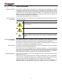
Important instructions concerning personal, operational and technical safety are marked
in the text as follows:
Symbol Description
Indicates a potential danger of an electric shock that may result in fatal
or serious injury.
Indicates a potential danger that may lead to slight or moderate injury.
The notes contain important information and useful tips for using the
system. Failure to observe them can render the measuring results
useless.
Working with products
from Megger
It is important to observe the general electrical regulations of the country in which the
device will be installed and operated, as well as the current national accident prevention
regulations and internal company rules (work, operating and safety regulations).
Use genuine accessories to ensure system safety and reliable operation. The use of
other parts is not permitted and invalidates the warranty.
Operating staff This system and its peripheral equipment may only be operated by trained or instructed
personnel. Anyone else must be kept away.
The system may only be installed by an authorised electrician. DIN VDE 0104 (EN
50191), DIN VDE 0105 (EN 50110) and the German accident prevention regulations
(UVV) define an electrician as someone whose knowledge, experience and familiarity
with the applicable regulations enables him to recognise potential hazards.
Intended application The PVS 100i is designed only to be operated via a direct connection to low voltage
networks up to 400 V.
When using the high voltage sensor HVS 120/36i, the PVS 100i can also be operated in
connection with a suitable insulating rod on medium and high voltage lines with up to
120 kV system voltage (corresponds to max. 70 kV phase to earth voltage).
Operating safety is only guaranteed when the system is used as intended. The
thresholds listed in the technical data may not be exceeded under any circumstances.
WARNING
CAUTION

7
Device in fully
functional condition
All components of the PVS 100i may only be used if they are in a fully functional state.
In the event of mechanical damage (e.g. crack in the housing) or dirt, the electrical
safety may be compromised. This especially applies to the high voltage sensor, since
damage to it could pose an immediate danger to life and limb.
To prevent any damage, the measuring device and high voltage sensor should be
handled with the utmost care. In case of doubt (e.g. if a part has fallen onto a hard
surface), the respective part should be sent to Megger or an authorised service
department for inspection.
Electromagnetic
radiation
This device is designed for industrial use. When used at home it could cause
interference to other equipment, such as the radio or television.
The interference level from the line complies with the limit curve B (living area), the
radiation level complies with the limit curve A (industrial area). Once the living area is
sufficiently far away from the planned area of operation (industrial area), equipment
there will not be impaired.

8
2
Quick start
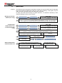
Purpose The following quick start guide is intended to enable you to put the PVS 100i into operation
and perform initial measurements without a great deal of training. In this guide, only the
really necessary operating steps and settings are described.
To learn more about the full range of system functions, it is therefore mandatory to also
read the following sections of the manual.
Starting up the base
station (once only)
Preparing the
mobile unit for use
in measuring (once
only)
Phase identification
with the mobile unit
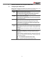
1
Configuration
Settings
Mode = Base
(see page Fehler! Textmarke nicht definiert.
f d t il )
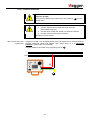
2
Put the base station into operation by plugging it into any network socket and check that GSM and GPS
reception is ensured (see page Fehler! Textmarke nicht definiert. for details). The unit should then
remain plugged into this socket exclusively so that the measurement profiles retain their validity.
3
Configuration
Settings
Mode = Mobil
(see page Fehler! Textmarke nicht definiert.
f d t il )
4
Configuration
Settings
Enter phone number of base
(see page Fehler! Textmarke nicht definiert.
f d t il )
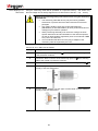
5
Create a measurement profile for every measurement scenario that arises in the mobile unit's area of
application if possible (see page Fehler! Textmarke nicht definiert. for details)
Connect mobile unit with known phase L1
(see page Fehler! Textmarke nicht definiert. for details)
Check that GSM and GPS reception
is ensured
Configuration
Select how the
voltage is tapped
New profile
Select the type of
power supply
0
Stop Save profile
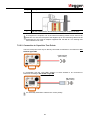
6
Connect mobile unit with phase to be identified
(see page Fehler! Textmarke nicht definiert. for details)
Check that GSM and GPS
reception is ensured
Select the appropriate
measurement profile
Select the type of
power supply
Read off phase

9
3
Technical Description
3.1 General Description
Requirement Precise knowledge of the phase assignment in an electrical power network is an
essential condition for safe and reliable operation.
This is true for all levels from the distribution network to the transport network for high-
voltage transmission lines. Phase identification on live systems is necessary when
preparing and executing network restructuring, for recording, updating and revising
planning documentation, and for planning and setting up new network systems.
The PVS 100i system allows safe and reliable identification of the phasing on live
systems, so that the phases can be assigned and labelled in order to prevent operating
errors with serious consequences, for example during switching operations.
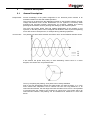
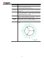
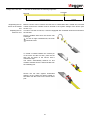
How it works The phases in a three-phase network are offset in time, as the following diagram shows:
If we observe the phase shift (120°) of each alternating current curve in a vector
diagram, the vectors form a symmetrical star:
Thus, by comparing the phasing, each phase can be clearly identified.
Due to the high propagation speed, the phase angle only drifts by about 1° in 8 km,
which means this comparison can be carried out even over long distances. In an
interconnected network, the load angle must also be taken into account. It is impossible
to forecast where the voltage to be measured is coming from. This means that in an
interconnected network, the phasing can be identified over distances of more than
50 km.
L1
L2
U
t
L1
L2
L3
L3

10
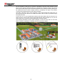
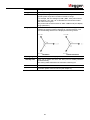
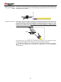
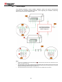
For the purpose of this type of “remote” comparison, the PVS 100i consists of two
devices, one of which (the base station) is connected to a reference phase. The second
device (the mobile unit) can be connected anywhere in the network, and the phasing can
be determined across various voltage levels by comparing the angle of the phase
currently being tested with that of the reference phase.
Automatic comparison with a direct indication of the phase assignment takes place by
synchronising the two devices via a GSM connection. GPS is used, to provide a highly
accurate time base.
If there are one or more transformers between the base station and the test point, the
effect of these vector groups and the associated phase shifts (multiples of 30°) can be
easily taken into account by entering appropriate correction values.
The following illustration shows typical examples of how the PVS 100i can be used
within a network, regardless of voltage levels and connection options:

11
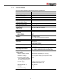
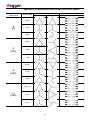
3.2
Technical Data
The PVS 100i is specified by the following technical parameters:
Parameter Value
Operating voltage
115 V / 230 V AC 50/60 Hz
Power consumption
100 VA
Battery
Lithium ion (12.6 V; 4.8 Ah)
Battery life
10 hours
Input voltage range of
measurement input U
X
5 V … 400 V
Operating temperature
-20 °C ... +50 °C
Storage temperature
-40 °C ... +60 °C
Dimensions
(W x H x D)
235 mm x 105 mm x 181 mm
Weight
3.2 kg
Precision
• up to 400 V
• up to 120 kV
±0,5°
±10°
Display
LCD touch screen
240 x 128 pixels (transflective display)
Memory
1 GB SD card
Interfaces
USB (Host)
GSM (900/1800 Mhz)
Radio (868/915 MHz)
Protection rating
IP 54 (with the housing closed)
IP 20 (open)
Measurement Category
according to IEC-61010
CAT IV 300 V (using the fused crocodile clips)
CAT II 300 V (without the fused crocodile clips)
High voltage sensor
(HVS 120/36i)
• Built-in wireless modem
868/915 MHz (depending on country)
• Maximum voltage
120 kV system voltage (70 kV phase to earth)
• Protection against flash
over initiation and bridging
according to EN 61243-1
36 kV
• Power supply
Integrated NiMH accumulator
(operating time approx. 7 h)
• Dimensions (Ø * L)
85 x 220 mm
• Weight
0.9 kg
• Protection rating
IP 43

12
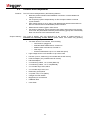
3.3
Features and Components
Features The PVS 100i is distinguished by the following features:
• Real-time phase indication with GSM/GPS connection or with available low
voltage connection.
• Can temporary operate independently of GPS reception thanks to internal
synchronization.
• High voltage sensor for up to 120 kV with bidirectional wireless transmission to
the PVS 100i and direct visual/audible phase indication.
• Measurement results logged in CSV format.
• Correction of switching groups between base station and mobile unit by zeroing.
As a result, the phase shifts caused by these switching groups are automatically
taken into account in the measurement result.
Scope of delivery
The scope of delivery may vary depending on the number of ordered devices. A
standard set consisting of two devices (base station and mobile unit) generally
includes the following components:
• Two basic devices in a Pelicase, each including
o GPS antenna, plugged in
o 900/1800 MHz GSM antenna, screwed on
o 868/915 MHz rod antenna, screwed on
o PDA stylus
o External GSM antenna (incl. 5 m cable and tripod)
• High voltage sensor HVS 120/36i incl. tip sensor head
• Hot stick (110 kV, 2038 mm) (not included with the US version)
• HVS US adapter (only included with US version)
• HR-LRM-Adapter
• 2 x measuring cables, 1.5 m, black (MK41-B)
• 2 x measuring cables, 1.5 m, red (MK42-B)
• 2 x crocodile clips, fused, black
• 2 x crocodile clips, fused, red
• Earth lead, green/yellow
• 2 x power cord, 2.0 m (NKG1)
• Charger for HVS 120/36i
• Bag/Trolley for accessories
• USB flash drive
• User Guide

13
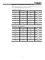
Optional accessories The following accessories can be ordered by your Megger representative, if required:
Accessories Description Order number
Hot stick 30 kV,
1038 mm
for use with HV sensor 820015301
Hot stick 30 kV,
1538 mm
for use with HV sensor 820015302
Measuring cable
MK 55
Adapter for direct measurement on LV
HRC fuses
820025178
Connection cable for
GPS module
20 m connection cable + stand 820014560 and
820016550
GPS mounting kit Bracket for external wall mounting (incl.
GPS antenna and connection cable)
820014566
External GSM antenna 5 m connection cable + tripod 820020946

14
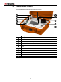
3.4
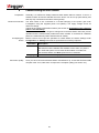
Connections and Controls
The PVS 100i has the following connections and controls:
Element Description
Mains power socket
On/off button
Slot for holding the PDA stylus
USB port for connection of USB flash drive
868/915 MHz rod antenna (pivoting) for communication with the high voltage
sensor
900/1800 MHz GSM antenna (folding and detachable)
LCD touch screen
GPS antenna (detachable)
Sockets for measuring voltage input
Earthing socket
1
2
3
4
5
6
7
8
9
10

15
4
Preparing the Units for Deployment
Updating the PVS
100i firmware
Proceed as follows to update the firmware of a device:
Step Description
1 Save the two files of type *.fla in the FIRMWARE directory of an empty USB
stick.
2
Plug the USB stick into the USB port of the turned-off device that is
connected to the mains voltage.
3
Turn the device on.
4 During booting, confirm the message on the screen with YES (by pressing the
touchpad on the display).
Result: The firmware installation begins.
Updating the high
voltage sensor
firmware
Proceed as follows to update the firmware of a high voltage sensor:
Step Description
1 Save the firmware *.bin file in the folder FIRMWARE on an empty USB stick.
2 Attach the charged HV-Sensor to the insulating rod and place it within proximity
of the mobile unit to which it is registered.
3
Switch on the mobile unit and then insert the USB stick into the device’s USB
port .
4 Under Configuration Settings call up the menu item HV sensor and tap
Update.
Result: If the HV sensor and the corresponding file are found, the update runs
automatically within 2 to 3 minutes.
4
4

16
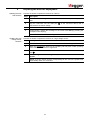
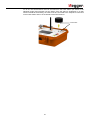
Installing / replacing
the SIM card
To install or exchange the SIM card, remove the 6 screws on the top of the device using a
Phillips screwdriver and take the hardware module out of the Peli case.
Briefly press on the yellow spring mechanism to eject the carriage from its position. The
SIM card must then be inserted into the carriage and pushed into the guide until you feel a
click.
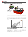
Charging the high
voltage sensor
The charging of the integrated battery is only possible when the device is switched off
which means that the HV sensor must be removed from the insulating rod.
The charging port of the HV sensor is located in the tip’s holder. To connect the charging
cable, the sensor head must first be unscrewed (see section 7.2.2.3). The supplied battery
charger is then connected to the underlying charging socket and plugged into a power
socket.
The charging procedure starts automatically (“Charge” LED lights up on the battery
charger) and takes about three hours. After charging is completed, the battery charger
switches to trickle charging (“Ready” LED is lit).
To optimise the life of the battery, it is recommended to occasionally (e.g. once per
quarter) discharge the battery completely and then fully recharge it. To discharge the
battery, the charging device must be connected to the charging socket and power socket
as described above with the “Discharge” button on the charging device pressed. Once
discharging is completed, the battery is automatically fully recharged.
Spring mechanism to
eject the carriage
Charging socket

17
5
General Operation
The PVS 100i has a robust design and has passed all practical and stress tests. It has
also withstood loads that have, in part, considerably exceeded the threshold values
required by the relevant standards.
Nevertheless, the PVS 100i and its system components are electronic measuring devices
which must be handled with due care and attention.
In particular, the display must not under any circumstances be placed under a large
amount of pressure!
For this reason, all detachable parts, such as e.g. the GPS antenna , the GSM
antenna and the stylus , must be attached to the correct place and the GSM
antenna must be placed horizontally by hand before the housing lid is closed.
Noncompliance can lead to damage to the device for which Megger offers no warranty.
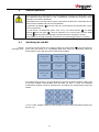
5.1 Switching On and Off
Normal
switching on/off
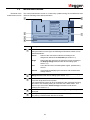
The device can be turned on by briefly pressing the on/off button . The LED lights up
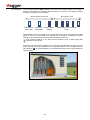
green when the device is on. Immediately after being turned on, the display shows the
quick selection menu with the stored measurement profiles:
If the GPS power reserve is not yet sufficiently charged or the GSM reception quality does
not provide reliable communication with the base (no bars or 1 bar), the individual
measurement profiles cannot be selected and, accordingly, the measurement cannot be
started.
In such a case, suitable measures must be taken to improve the GPS/GSM reception (see
Section 5.4).
CAUTION
6
3
6
8
7
GSM
GPS
LVUK.MSL
LV
LVWPD.MSL
LV
TEST.MSL
LV
LV1.MSL
LV
CAP1.MSC
CAP
CAP2.MSC
CAP
HV11.MSH
HV
Configuration
PVS
2

18
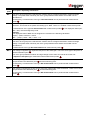
Manual and
automatic switch-off
To turn the device off, briefly press the on/off button again. If a standby time is specified in
the device settings (see section 7.1), the device is not completely turned off but switched
to standby mode (applicable only to mobile units). In this mode, both the GSM and GPS
reception as well as the synchronicity of the internal oscillator remain functional. This has
the advantage that the mobile unit is ready immediately after pressing the on/off button
again.
To completely turn off the mobile unit before the time expires, press the Switch off
immediately button.
If no standby time is set, however, or if this device is configured as base station, then it is
switched off immediately after the on/off button is pressed.
Hardware reset
If the device stalls during operation or exhibits obvious malfunctions, the on/off
button can be used to reset the hardware. To do this, keep the button pressed for at
least 10 seconds. Then wait another 10 seconds before briefly pressing the button to
switch the device on again.
This type of reset also resets the clock and the battery indicator. While the clock
automatically corrects itself when a GPS signal is received, the battery indicator is only
synchronised after the next charging of the battery.
5.2 Mains and Battery Operation
Mains operation The PVS 100i can be operated with an external power supply (115 V / 230 V AC). To do
this, the mains supply socket must be connected to the mains using the power cable
supplied.
Battery operation In contrast to the base station, a mobile unit must not necessarily be connected to mains
supply. It may be operated from a built-in, maintenance-free lithium ion battery. Under
normal conditions this will give up to 10 hours of operation.
The battery status indicator shows the remaining battery capacity when the device is
switched on.
Charging the battery The battery is charged automatically as soon as the PVS 100i is connected to mains
power via the mains supply socket . It takes roughly two hours to fully charge a
completely discharged battery. To prolong the battery life, it is advisable to completely
charge and discharge it at least twice a year.
The battery is protected from deep discharge, overcharging and overheating. The device
can remain connected to the mains even after the battery is fully charged. Trickle
charging then takes place.
2
1
Fully charged Completely discharged
1

19
5.3
Using the Stylus
All entries on the PVS 100i are made on the touch-screen using the stylus. To activate a
touch button, you only need to gently touch it with the tip of the stylus. Always put the
stylus back in its slot after use.
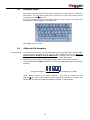
If you have to enter a string of characters (such as a file name) in the system, the
dialogue shown below appears in the display area.
Select OK to finish the entry.
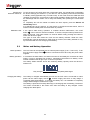
5.4 GSM and GPS Reception
GSM reception To synchronize via call-up over the GSM network, both the base station and the mobile
unit of the PVS 100i must each be equipped with a GSM SIM card. The PIN code
request must be disabled for both SIM cards! If necessary, the cards must first be
inserted into a mobile phone, with which this function can be deactivated.
Detailed information about installing/replacing SIM cards can be found in chapter 4.
The bar graph labelled GSM indicates the current GSM signal quality when the device is
turned on.
Under difficult conditions, e.g. within buildings, it may help to unscrew the rod
antenna and connect the external antenna (optional accessories) in its place. This
should then be positioned outside the building if possible, or near windows.
0
1
2
3
4
5
6
7
8
9
Q
W
E
R
T
Y
U
I
O
P
A
S
D
F
G
H
J
K
L
_
Z
X
C
V
B
N
M
<
>
OK
3
6
Very good reception No reception (or no card)

20
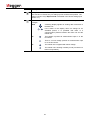
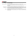
GPS reception
The bar graph labelled GPS indicates the current GPS signal quality or the reserve
power of the internal time reference when the device is turned on. The display changes
as follows, depending on the situation:
As illustrated by the above graphic, the internal power reserve synchronizes to the GPS
signal as soon as it is received. Once this process is complete, a sufficiently accurate
time base can be ensured even without GPS reception for an hour.
Even outside buildings it can take several minutes to find a GPS signal after
switching on the device.
If the device is used inside a building, such as a switching substation, and the one-hour
power reserve will not be sufficient for the expected duration of the measurement, the
GPS antenna on the base station can be positioned outside and connected with the
optional cable.
8
Power reserve
charged
GPS reception is ensured No GPS for 1 hour
Searching for
GPS signal
Receiving
GPS signal
Power reserve is decreasing
slowly
Pagina se încarcă...
Pagina se încarcă...
Pagina se încarcă...
Pagina se încarcă...
Pagina se încarcă...
Pagina se încarcă...
Pagina se încarcă...
Pagina se încarcă...
Pagina se încarcă...
Pagina se încarcă...
Pagina se încarcă...
Pagina se încarcă...
Pagina se încarcă...
Pagina se încarcă...
Pagina se încarcă...
Pagina se încarcă...
Pagina se încarcă...
Pagina se încarcă...
Pagina se încarcă...
Pagina se încarcă...
Pagina se încarcă...
Pagina se încarcă...
Pagina se încarcă...
Pagina se încarcă...
Pagina se încarcă...
Pagina se încarcă...
Pagina se încarcă...
-
 1
1
-
 2
2
-
 3
3
-
 4
4
-
 5
5
-
 6
6
-
 7
7
-
 8
8
-
 9
9
-
 10
10
-
 11
11
-
 12
12
-
 13
13
-
 14
14
-
 15
15
-
 16
16
-
 17
17
-
 18
18
-
 19
19
-
 20
20
-
 21
21
-
 22
22
-
 23
23
-
 24
24
-
 25
25
-
 26
26
-
 27
27
-
 28
28
-
 29
29
-
 30
30
-
 31
31
-
 32
32
-
 33
33
-
 34
34
-
 35
35
-
 36
36
-
 37
37
-
 38
38
-
 39
39
-
 40
40
-
 41
41
-
 42
42
-
 43
43
-
 44
44
-
 45
45
-
 46
46
-
 47
47


