
GF100 Series
Installation and Operation Manual
X-TMF-GF100-Series-MFC-eng
Part Number: 541B137AAG
April, 2017
Brooks
®
GF100 Series
High Purity/Ultra-High Purity Digital Thermal
Mass Flow Devices
Model GF125 Analog I/O Model GF125 Digital I/O
Model GF135 Analog I/O Model GF121 Analog I/O

Installation and Operation Manual
X-TMF-GF100-Series-MFC-eng
Part Number: 541B137AAG
April, 2017GF100 Series
ESD (Electrostatic Discharge)
CAUTION: This instrument contains electronic components that are susceptible to damage by static electricity. Proper handling procedures must be observed
during the removal, installation or other handling of internal circuit boards or devices.
Handling Procedure:
1. Power to unit must be removed.
2. Personnel must be grounded, via a wrist strap or other safe, suitable means before any printed circuit card or other internal device is installed,
removed or adjusted.
3. Printed circuit cards must be transported in a conductive container. Boards must not be removed from protective enclosure until immediately before
installation. Removed boards must immediately be placed in protective container for transport, storage or return to factory.
Comments
This instrument is not unique in its content of ESD (electrostatic discharge) sensitive components. Most modern electronic designs contain components
that utilize metal oxide technology (NMOS, SMOS, etc.). Experience has proven that even small amounts of static electricity can damage or destroy these
devices. Damaged components, even though they appear to function properly, exhibit early failure.
Brooks Instrument designs, manufactures and tests its products to meet many national and international standards. These products must be properly
installed, operated and maintained to ensure they continue to operate within their normal specifications. The following instructions must be adhered to
and integrated into your safety program when installing, operating and maintaining Brooks Instrument products.
• To ensure proper performance, use qualified personnel to install, operate, update, program and maintain the product.
• Read all instructions prior to installing, operating and servicing the product. If this instruction manual is not the correct manual, please see back cover
for local sales office contact information. Save this instruction manual for future reference.
WARNING: Do not operate this instrument in excess of the specifications listed in the Instruction and Operation Manual. Failure to heed
this warning can result in serious personal injury and / or damage to the equipment.
• If you do not understand any of the instructions, contact your Brooks Instrument representative for clarification.
• Follow all warnings, cautions and instructions marked on and supplied with the product.
WARNING: Prior to installation ensure this instrument has the required approval ratings to meet local and national codes. Failure to heed this warning can
result in serious personal injury and / or damage to the equipment.
• Install your equipment as specified in the installation instructions of the appropriate instruction manual and per applicable local and national codes.
Connect all products to the proper electrical and pressure sources.
• Operation: (1) Slowly initiate flow into the system. Open process valves slowly to avoid flow surges. (2) Check for leaks around the flow meter inlet
and outlet connections. If no leaks are present, bring the system up to the operating pressure.
• Please make sure that the process line pressure is removed prior to service. When replacement parts are required, ensure that qualified people use
replacement parts specified by Brooks Instrument. Unauthorized parts and procedures can affect the product's performance and place the safe
operation of your process at risk. Look-alike substitutions may result in fire, electrical hazards or improper operation.
• Ensure that all equipment doors are closed and protective covers are in place to prevent electrical shock and personal injury, except when
maintenance is being performed by qualified persons.
WARNING: For liquid flow devices, if the inlet and outlet valves adjacent to the devices are to be closed for any reason, the devices must be completely
drained. Failure to do so may result in thermal expansion of the liquid that can rupture the device and may cause personal injury.
All pressure equipment with an internal pressure greater than 0.5 bar (g) and a size larger than 25mm or 1" (inch) falls under the Pressure Equipment Directive (PED).
• The Specifications Section of this manual contains instructions related to the PED directive.
• Products described in this manual are in compliance with EN directive 2014/34/EU.
• All Brooks Instrument Flowmeters fall under fluid group 1.
• Products larger than 25mm or 1" (inch) are in compliance with PED category I, II or III.
• Products of 25mm or 1" (inch) or smaller are Sound Engineering Practice (SEP).
The Brooks Instrument (electric/electronic) equipment bearing the CE mark has been successfully tested to the regulations of the Electro Magnetic
Compatibility (EMC directive 2014/30/EU).
Special attention however is required when selecting the signal cable to be used with CE marked equipment.
Quality of the signal cable, cable glands and connectors:
Brooks Instrument supplies high quality cable(s) which meets the specifications for CE certification.
If you provide your own signal cable you should use a cable which is overall completely screened with a 100% shield.
“D” or “Circular” type connectors used should be shielded with a metal shield. If applicable, metal cable glands must be used providing cable screen clamping.
The cable screen should be connected to the metal shell or gland and shielded at both ends over 360 Degrees.
The shield should be terminated to an earth ground.
Card Edge Connectors are standard non-metallic. The cables used must be screened with 100% shield to comply with CE certification.
The shield should be terminated to an earth ground.
For pin configuration : Please refer to the enclosed Instruction Manual.
European Pressure Equipment Directive (PED)
European Electromagnetic Compatibility (EMC)
Essential Instructions
Read before proceeding!

GF100 Series
Installation and Operation Manual
X-TMF-GF100-Series-MFC-eng
Part Number: 541B137AAG
April, 2017
Dear Customer,
We appreciate this opportunity to service your flow measurement and control requirements with a Brooks
Instrument device. Every day, flow customers all over the world turn to Brooks Instrument for solutions to their gas
and liquid low-flow applications. Brooks provides an array of flow measurement and control products for various
industries from biopharmaceuticals, oil and gas, fuel cell research and chemicals, to medical devices, analytical
instrumentation, semiconductor manufacturing, and more.
The Brooks product you have just received is of the highest quality available, offering superior performance,
reliability and value to the user. It is designed with the ever changing process conditions, accuracy requirements
and hostile process environments in mind to provide you with a lifetime of dependable service.
We recommend that you read this manual in its entirety. Should you require any additional information concerning
Brooks products and services, please contact your local Brooks Sales and Service Office listed on the back cover
of this manual or visit www.BrooksInstrument.com.
Yours sincerely,
Brooks Instrument

Installation and Operation Manual
X-TMF-GF100-Series-MFC-eng
Part Number: 541B137AAG
April, 2017GF100 Series
THIS PAGE WAS
INTENTIONALLY
LEFT BLANK

i
GF100 Series
Installation and Operation Manual
X-TMF-GF100-Series-MFC-eng
Part Number: 541B137AAG
April, 2017
Contents
Paragraph Page
Number Number
Section 1 General Information
1-1 Introduction ................................................................................................................................... 1-1
1-2 How to Use This Manual ...............................................................................................................1-1
1-3 Product Support References.........................................................................................................1-2
1-4 Notice and Caution Statements..................................................................................................... 1-2
1-5 Product Warranty .......................................................................................................................... 1-2
1-6 How to Order a GF100 Series Device........................................................................................... 1-2
1-7 Industry Standard References.......................................................................................................1-2
1-8 GF100 Series Gas Table ............................................................................................................... 1-2
1-9 Glossary of Terms and Acronyms ................................................................................................. 1-2
1-10 Description ....................................................................................................................................1-5
1-11 Specifications for GF100 Series Devices ...................................................................................... 1-8
Section 2 Installation
2-1 General ......................................................................................................................................... 2-1
2-2 Receipt of Equipment.................................................................................................................... 2-1
2-3 Recommended Storage Practice .................................................................................................. 2-1
2-4 Return Shipment ...........................................................................................................................2-1
2-5 Transit Precautions ....................................................................................................................... 2-2
2-6 Removal from Storage .................................................................................................................. 2-2
2-7 Gas Connections...........................................................................................................................2-2
2-8 In-Line Filter .................................................................................................................................. 2-2
2-9 Mechanical Installation .................................................................................................................. 2-2
2-10 Flow Controller Installation Arrangement ...................................................................................... 2-3
2-11 Purge the Gas Supply Line Before GF100 Series Installation....................................................... 2-4
2-12 Position and Mount the GF100 Series .......................................................................................... 2-5
2-13 Perform a Leak Test...................................................................................................................... 2-7
2-14 Zeroing Setup Process.................................................................................................................. 2-7
2-15 Zeroing the GF100 Series............................................................................................................. 2-7
2-15-1 Zeroing the GF100 Series Pressure Transducer from the LCD Display Panel ............................. 2-8
2-15-2 Zeroing GF100 Series Flow from LCD Display Panel ................................................................... 2-9
2-16 Performance Checks .................................................................................................................... 2-9
2-17 Introduction to the MultiFlo
TM
Configurator ...................................................................................2-10
2-18 Using the MultiFlo Configurator.................................................................................................... 2-10
2-19 Electrical Connections.................................................................................................................. 2-12
2-19-1 DeviceNet Connections................................................................................................................2-12
2-19-2 Analog/RS485 Connections ......................................................................................................... 2-13
2-19-3 EtherCat Connections .................................................................................................................. 2-14
2-20 GF135 Inlet Valve Installation....................................................................................................... 2-16
2-21 GF135 Commissioning.................................................................................................................2-17
Section 3 Operation
3-1 General ......................................................................................................................................... 3-1
3-2 Theory of Operation for Flow Measurement ................................................................................. 3-1
Section 4 Maintenance & Troubleshooting
4-1 Overview .......................................................................................................................................4-1
4-2 Maintenance.................................................................................................................................. 4-1
4-3 Troubleshooting............................................................................................................................. 4-3
4-4 Troubleshooting Checklist .............................................................................................................4-3
4-5 GF100 Series Troubleshooting Guide ........................................................................................... 4-4
Section 5 Product Description Code
5-1 Overview .......................................................................................................................................5-1
Appendix A: GF100 Series Gas Table
A-1 Overview .......................................................................................................................................A-1
Appendix B: GF100 Series Patents
B-1 Overview .......................................................................................................................................B-1
Appendix C: Essential Instructions
C-1 Overview .......................................................................................................................................C-1
Warranty, Local Sales/Service Contact Information....................................................................... Back Cover

ii
GF100 Series
Installation and Operation Manual
X-TMF-GF100-Series-MFC-eng
Part Number: 541B137AAG
April, 2017
Contents
Figure Page
Number Number
1-1 GF100 Series High Performance Gas Flow Controller Analog and Digital.................................... 1-1
1-2 LCD Display ..................................................................................................................................1-7
1-3 Dimensions - GF100/GF120/GF125 Series ................................................................................. 1-15
1-4 Dimensions - GF135, DeviceNet.................................................................................................. 1-16
1-5 Dimensions - GF135, RS485 .......................................................................................................1-17
1-6 Dimensions - GF101/GF121/GF126 ............................................................................................ 1-18
1-8 Dimensions - GF100/GF120/GF125, GF101/GF121/GF126 Series with EtherCAT Communications1-19
2-1 Typical Gas Supply Arrangement with Non-PTI MFC.................................................................... 2-4
2-2 Typical Gas Supply Arrangement with PTI MFC ........................................................................... 2-4
2-3 GF100 Series Mounting Attitude Positions.................................................................................... 2-5
2-4 GF100 Series Mounted to K1 Series Substrate Blocks................................................................. 2-6
2-5 Mounting Screws Torque Pattern .................................................................................................. 2-6
2-6 Display with PSI Reading ..............................................................................................................2-8
2-7 Display Reading Zero PSI .............................................................................................................2-8
2-8 Display Set to %FS ...................................................................................................................... 2-10
2-9 % Flow Display Set to Zero .......................................................................................................... 2-10
2-10 MultiFlo Cable Adapter ................................................................................................................. 2-11
2-11 USB-RS485 Converter (214F027AAA) ........................................................................................ 2-11
2-12 Diagnostic Port Locations ............................................................................................................ 2-11
2-13 GF100 Series DeviceNet Connection ..........................................................................................2-12
2-14 GF100 Series with 9-Pin Analog Connector ................................................................................. 2-15
2-15 Analog 9-Pin Connector (M).........................................................................................................2-15
2-16 GF100 with EtherCat Communications, M8 Power Connector Location...................................... 2-14
2-17 M8 Power Connector Drawing ..................................................................................................... 2-14
2-18 GF100 Series Electrical Interface Options ...................................................................................2-15
2-19 GF135 Series Showing Inlet/Outlet Pneumatic Isolation Valve Lines........................................... 2-16
3-1 GF100 Series Operating Principles............................................................................................... 3-2
Table Page
Number Number
1-1 Industry Standard References.......................................................................................................1-3
1-2 Terms and Acronyms ....................................................................................................................1-4
1-3 Specifications for Standard GF100/GF120/GF125 Series.............................................................1-9
1-4 Specifications for Safe Delivery System (SDS) GF120 Series..................................................... 1-10
1-3 Specifications for GF100/GF120/GF125 Series with EtherCAT Communications ....................... 1-11
1-6 Specifications for GF135 Series...................................................................................................1-12
1-7 Specifications for GF101/GF121/GF126 Series ........................................................................... 1-13
1-8 Specifications for GF101/GF121/GF126 Series with EtherCAT Communications ....................... 1-14
2-1 K1 Series Fasteners......................................................................................................................2-7
2-2 K1 Substrate Torque Data .............................................................................................................2-7
2-3 Gas and Flow Ranges - MultiFlo Configurable - N2 Equivalent ...................................................2-10
4-1 Environmental Factors ..................................................................................................................4-3
4-2 GF100 Series Troubleshooting Guide ...........................................................................................4-4
5-1 GF100, GF120 & GF125 Series Product Description Code..........................................................5-1
5-2 GF100, GF120 & GF125 Series with EtherCAT Communications Product Description Code ......5-3
5-3 Model GF135 Product Description Code....................................................................................... 5-4
5-4 GF101, GF121 & GF126 Series Product Description Code..........................................................5-5
5-5 GF101, GF121 & GF126 Series with EtherCAT Communications Product Description Code ......5-6
A-1A GF100 Series Gas Table - Codes 1-108, Bins SH40 to SH50 ......................................................A-1
A-1B GF100 Series Gas Table - Codes 109-875, Bins SH40 to SH50 ..................................................A-2
A-1C GF100 Series Gas Table - Codes 878-5022, Bins SH40 to SH50 ................................................A-2
B-1 GF100 Series Patents ...................................................................................................................B-1

1-1
GF100 Series
Installation and Operation Manual
X-TMF-GF100-Series-MFC-eng
Part Number: 541B137AAG
April, 2017
Section 1 Introduction
1-1 Introduction
Designed for semiconductor, MOCVD , and other gas flow control
applications that require a high purity all-metal flow path, the Brooks
GF100 Series mass flow controllers and meters deliver outstanding
performance, reliability, and flexibility. Process throughput and yield are
maximized while process costs are reduced by the GF100 Series featuring:
• Ultra fast settling time for quick start up and very rapid process steps
• MultiFlo™ gas and range configurability enabling reconfiguration without
removing device from the gas line
• An independent diagnostic/service port to troubleshoot or change flow
conditions without removing the mass flow controller from service
• Long-term stability due to extremely low wetted surface area, and
corrosion resistant Hastelloy
®
sensor and valve seat
Optional model variations including—pressure transient insensitivity (PTI)
and Safe Delivery System (SDS)
Figure 1-1 GF100 Series High Performance Gas Flow Controller Analog and Digital
1-2 How to Use This Manual
This manual is intended to provide the user with all the information
necessary to install, operate, troubleshoot and maintain these thermal
mass flow devices. The manual is organized in the following sections:
Section 1 Introduction
Section 2 Installation
Section 3 Operation
Section 4 Maintenance and Troubleshooting
Section 5 Product Description Code
Appendix A GF100 Series Gas Table
Appendix B GF100 Series Patents
Appendix C Essential Instructions
Warranty, Local Sales/Service Contact Information
It is recommended that this manual be read in its entirety before attempting
to operate or repair these devices.

1-2
GF100 Series
Installation and Operation Manual
X-TMF-GF100-Series-MFC-eng
Part Number: 541B137AAG
April, 2017
Section 1 Introduction
1-3 Product Support References
Refer to www.BrooksInstrument.com for Brooks sales and service
locations and to obtain other documents that support the GF100 Series.
Those documents include:
- Brooks MultiFlo
TM
Configurator Quick Start Manual:
X-SW-MultiFlo-Config-QS-eng. part Number 541B167AAG
- Brooks GF100 Series data sheets:
DS-TMF-GF100-Series-MFC-eng
DS-TMF-GF135-Series-MFC-eng
DS-TMF-GF121-Series-MFC-eng
DS-DPT-EtherCAT-GF100-Series-eng
1-4 Notice and Caution Statements
Warning, caution and notice statements are located throughout this manual
in the ANSI format. A WARNING statement indicates a potentially
hazardous situation which, if not avoided, COULD result in death or serious
injury. A CAUTION statement indicates a potentially hazardous situation
which, if not avoided, MAY result in minor or moderate injury. It may also be
used to alert against unsafe practices. A NOTICE statement describes
specific information that requires special attention.
1-5 Product Warranty
Product warranty information can be found on the Back Cover of this
Manual and on the Brooks website at www.BrooksInstrument.com. This
information provides general warranty information, limitations, disclaimers,
and applicable warranty periods according to product group.
1-6 How to Order a GF100 Series Device
Refer to Section 5.
1-7 Industry Standard References
Refer to Table 1-1.
1-8 GF100 Series Gas Table
Refer to Appendix A.
1-9 Glossary of Terms and Acronyms
Refer to Table 1-2

1-3
GF100 Series
Installation and Operation Manual
X-TMF-GF100-Series-MFC-eng
Part Number: 541B137AAG
April, 2017
Section 1 Introduction
Table 1-1 Industry Standard References
Reference Number Reference Description
MIL-STD-810 Method 514.4, Category 1, Transportation Requirement
Method 516.4, Procedure 1, Functional Shock Test Requirement
SEMI E12 Standard temperature and pressure
SEMI E16 Guideline for determining and describing MFC leak rates
SEMI E17 Guideline for MFC transient characteristics tests
SEMI E18 Guideline for temperature specifications of the MFC
SEMI E27 Standard for MFC and MFM linearity
SEMI E28 Guideline for pressure specifications for the MFC
SEMI E52 Practice for referencing gases used in digital MFCs
SEMI E54 Sensor actuator network connections for DeviceNet
SEMI E56 Test method for detemining accuracy, linearity, repeatability, short-term
reproducibility, hystereses of thermal MFCs
SEMI E66 Test method for determining particle contribution by MFCs
SEMI E67 Test method for determining reliabilty of MFCs
SEMI E68 Test method for determining warm-up time of MFCs
SEMI E69 Test method for reproducibilty and zero drift for thermal MFCs
SEMI E80 Test method for determining attitude sensitivity of MFCs
SEMI E16-90 Guidelines for determining and describing mass flow controllers leak rates
SEMI F19 Specification for the finish of the wetted surface of electro polished
216L stainless steel components
SEMI F20 Specifications for 316L stainless steel bar, extruded shapes, plate, and
investment castings for components used in ultra-high purity semi
manufacturing applications
SEMI F36 Guide for dimensions and connections of gas distribution components
SEMI F37 Method for determination of surface roughness parameters for gas
distribution system components
SEMI F44 Guideline for standardization of machined stainless steel weld fittings
SEMI F45 Guideline for standardization of machined stainless steel reducing fittings
SEMI F47 Specifications for semiconductor processing equipment
voltage sag immunity
SEMI S2 Environmental, Health and Safety Guidelines
SEMI S9 Dielectric testing
SEMI S10 Risk assessment
SEMI S12 Decontamination of fielded products
ETG.1000.2 Physical Layer service definition and protocol specification
ETG.1000.3 Data Link Layer service definition
ETG.1000.4 Data Link Layer protocol specification
ETG.1000.5 Application Layer service definition
ETG.1000.6 Application layer protocol specification
ETG.1020 EtherCAT Protocol Enhancements
ETG.2000 EtherCAT Slave Information
ETG.5001.1 Modular Device Profile - Part 1: General MDP Device Model
ETG.5003.1 Semiconductor Device profile - Part 1: Common Device Profile (CDP)
ETG.5003.2020 Specific Device Profile: Enhanced Mass Flow Controller
ETG.5003.2021 Specific Device Profile: Mass Flow Controller
ETG.5003.2022 Specific Device Profile: Mass Flow Meter
ETG.5003.2023 Specific Device Profile: Enhanced Mass Flow Meter

1-4
GF100 Series
Installation and Operation Manual
X-TMF-GF100-Series-MFC-eng
Part Number: 541B137AAG
April, 2017
Section 1 Introduction
Term or Acronym Definition
CSR Customer Special Requirement
CVD Chemical Vapor Deposition
DeviceNet A 5-wire local network I/O communication device
that employs a command/response
communication protocol
DSP Digital Signal Processor
EPI Epitaxy (EPI). A process technology where a pure silicon
crystalline structure is deposited or “grown” on a
bare wafer, enabling a high-purity starting point
for building the semiconductor device.
HBD Horizontal Base Down
GF100 Series Integrated Flow Controller
F.S. Full Scale
LED Light Emitting Diode
MFC Mass Flow Controller
MultiFlo Configurator I/O communication software package that
configures gas and flow ranges
MultiFlo Technology A physics-based calibration methodology that
enables gas and flow range configuration within
a defined standard configuration
PID Proportional Integral Derivative Controller
PSIA Pounds per Square Inch Absolute
PSID Pounds per Square Inch Differential
PSIG Pounds per Square Inch Gauge
PTI Pressure Transient Insensitive. Reduces the
effect of pressure fluctuations in gas flow.
Applicable to GF125 only.
ROR As pressure increases, flow increases at a
pressure rate of rise, or ROR.
HC Standard Configuration w/ Hastelloy® sensors
(to reduce reaction to corrosive gases)
S.P. Setpoint
Step Technology Enables fast set point control through a high
speed DSP and low volume drive circuit
VIU Vertical mounting attitude with inlet side facing up
Table 1-2 Terms and Acronyms

1-5
GF100 Series
Installation and Operation Manual
X-TMF-GF100-Series-MFC-eng
Part Number: 541B137AAG
April, 2017
Section 1 Introduction
1-10 Description
Ultra Fast Response
The Brooks GF Series patented flow sensor combined with a high speed
ARM processor and fast acting diaphragm-free valve assembly enables:
• Faster response and settling time for improved wafer throughput
• Ultra-fast 1-2 second etch step processing
• Reduced diverted gas consumption and associated abatement costs
• Time sensitive gas delivery steps in Atomic Layer Deposition
• User programmable start-up function for processes requiring a slow
ramped gas turn-on or time critical transitions between flow rates
MultiFlo™ Gas and Range Configurability
The Brooks MultiFlo technology delivers exceptional improvement in
process gas accuracy for linear and non-linear gases. This is achieved
through advanced gas modeling and optimized through actual gas testing.
Brooks MultiFlo
TM
allows the device to be quickly and easily configured for
another gas and/or flow range without sacrificing accuracy or rangability.
Selecting a new gas automatically creates a new calibration curve,
establishes optimized PID settings for dynamic control, automatically
compensates for gas density effects, and ensures smooth overshoot-free
transitions between flow rates with excellent steady-state stability. Brooks
MultiFlo technology offers unparalleled flexibility. An extensive gas
database is provided and a single device can be quickly programmed for
thousands of different gas and flow range combinations. Process benefits
achieved:
• Mass flow controller full scale full range can be rescaled down typically by a
factor of 3:1 with no impact on accuracy, turndown or leak by specifications
• Optimum process and inventory flexibility resulting in dramatically reduced
inventory costs
• Fewer configurations/bin sizes required to support many different processes
• Less down-time with rapid process recovery
MultiFlo
TM
Support References: Brooks MultiFlow Configurator Quick
Start Guide (X-SW-MultiFlo-Config-QS-eng (Part Number: 541B167AAG))
MultiFlo
TM
Configurator Accessory Kits:
778Z010ZZZ Basic MultiFlo Configurator Kit
*Software, MultiFlo Configurator
A331710003 Cable Assembly 2.5mm
214F027AAA USB-RS485 Converter with DB-9 female
778Z011ZZZ Basic MultiFlo Configurator Kit w/Power Supply and
Adapter Cables *Software, MultiFlo Configurator
A331710003 Cable Assembly 2.5mm
214F027AAA USB-RS485 Converter with DB-9 female
A332295001 Power Supply MFC
A332297002 Cable, Power, 9-Pin
A332297001 Cable, Power, DeviceNet
* MultiFlo Configurator Software is available on the Brooks Instrument
website at: www.BrooksInstrument.com/MultiFlo
www.BrooksInstrument.com/Documentation&Downloads

1-6
GF100 Series
Installation and Operation Manual
X-TMF-GF100-Series-MFC-eng
Part Number: 541B137AAG
April, 2017
Section 1 Introduction
Pressure Transient Insensitivity (PTI)— Included with all GF125 &
GF135 models
Cost and space constraints are driving gas panel designers to remove
point-of-use pressure regulators and pressure monitoring components from
the process design and rely solely on the mass flow controller to accurately
control the process under dynamic pressure conditions. The Brooks GF125
& GF135 (PTI) devices utilize a patented control algorithm that inverts the
pressure signal, compares it to the pre-fluctuation signal and drives real-
time valve position compensation to maintain stable flow. Enhanced
pressure transient is achieved through faster sensing, quicker processing,
and a reduction in internal dead-volume between the sensors and valve
orifice.
GF101/121/126 based on the same technology and design as the low
flow GF's (same sensor, same electronics, low power support)
• Smaller footprint than competitive MFC's
• Handles flow rates up to 300 slpm
• Metal seal for durability and high leak integrity
• Proprietary sensor technology
• Precise flow control with fast sub-1 second settling time
• 1% of reading accuracy
• Corrosion-resistant Hastelloy C-22 sensor tube
Optional Safe Delivery System (SDS)— GF120 model only
The Safe Delivery System (SDS) enhanced GF120 model is a state-of-the-
art low pressure drop devices for the delivery of sub atmospheric safe
delivery system gases used in Implant and Etch processes. The Brooks
GF120 SDS models are available in full scale flow ranges 4 sccm -1 slpm.
Advanced Thermal Flow Measurement Sensor
Brooks proprietary highly corrosion resistant Hastelloy C-22 sensor with an
enhanced sensor manufacturing and burn in process incorporates a unique
orthogonal sensor mounting orientation to eliminate sensor drift caused by
valve heating effects and eliminates thermal siphoning effects. This unique
sensor configuration includes an optimized temperature profile for gases
prone to thermal decomposition. This design results in:
• Enhanced signal to noise performance for improved accuracy at low
set points
• Superior reproducibility at elevated temperature through new
isothermal packaging and onboard conditioning electronics with
ambient temperature sensing and compensation
• Improved long-term stability

1-7
GF100 Series
Installation and Operation Manual
X-TMF-GF100-Series-MFC-eng
Part Number: 541B137AAG
April, 2017
Section 1 Introduction
Figure 1-2 LCD Display
High Purity Flow Path
The Brooks GF Series has an all metal, corrosion resistant Semi F20
compliant wetted flow path with highly corrosion resistant Hastelloy C-22
valve seat and jet orifice. The GF120, GF125 & GF135 devices are
constructed with a 4μ
inch Ra max surface finish while the GF100 is
constructed with a 10μ inch Ra.
• Overall reduced surface area and un-swept volumes for faster dry-down
during purge steps
• Long-term sensor and device stability for maximum yield and throughput
Extensive Mechanical Configurations
GF Series supports all metal seal/UHP industry gas connection interface
standards for full OEM and process coverage.
• Downport 79.8mm and 92mm C-seal and W-seal on 1-1/8" and 1-1/2"
bodies
• 124mm 4 VCR on 1-1/2" body
Enhanced Diagnostics and User Interface
The mass flow controller is one of the most complex and critical
components in gas delivery systems. When dealing with ultra-high-purity
gas distribution or highly toxic or corrosive gases, removing the mass flow
controller to assess functionality should be the last resort. Brooks GF
Series devices provide for in-line device evaluation and instantaneous
troubleshooting through:
• Embedded self test routines and independent diagnostic/service port
• High visibility LCD display with easy accessible push button for local
indication of Flow (%), Temperature (
o
C), Pressure (PSIA/kPa) and
Network Address
• Zero button to easily re-zero the device during scheduled maintenance
• Rotatable display with a push button to enable improved readability based
on how the MFC is mounted. Simply hold button down for at least 3
seconds to rotate display. This featue is standard for GF135 and GF101/
GF121/GF126 and available for GF100/GF120/GF125.
This combination of features results in limiting service interruption and
reduced downtime.

1-8
GF100 Series
Installation and Operation Manual
X-TMF-GF100-Series-MFC-eng
Part Number: 541B137AAG
April, 2017
Section 1 Introduction
Communication Interfaces
The GF100 Series supports analog 0-5 Vdc, RS485, DeviceNet™ and
EtherCAT
®
communication protocols. Analog connections can be accessed
via the DeviceNet or RS485 or Analog only connector options. DeviceNet
and RS485 are multi-drop connections that allow a maximum of 64 devices
for DeviceNet and 32 devices for RS485 to be connected on the same
network. Brooks Instrument’s DeviceNet profile has been certified by the
ODVA™ (Open DeviceNet Vendor’s Association). EtherCAT is an Ethernet
based communications system know for its high cycle time and cost
efficient cabling and master application solutions. The EtherCAT GF100
Series devices conform to the ETG.5003 Semiconductor Device Profile
specification. A range of low profile adapter cables facilitate replacing
previously installed devices eliminating the need to carry multiple devices
of the same gas/range but different electrical connectors.
1-11 Specifications for GF100 Series Devices
See Table 1-3 for specifications for standard GF100 Series.
See Table 1-4 for specifications for the Safe Delivery System (SDS) GF120
Series.
See Table 1-5 for specifications for standard GF100 Series-EtherCAT
See Table 1-6 for specifications for the GF135 Series.
See Table 1-7 for specifications for the GF121 Series.
See Table 1-8 for specifications for the GF121 Series-EtherCAT
See Figure 1-3 for dimensions for the GF100 Series.
See Figures 1-4 & 1-5 for dimensions for the GF135 Series.
See Figure 1-6 for dimensions for the GF121 Series.
See Figure 1-7 for dimensions for the GF100/GF121 Series-EtherCAT

1-9
GF100 Series
Installation and Operation Manual
X-TMF-GF100-Series-MFC-eng
Part Number: 541B137AAG
April, 2017
Section 1 Introduction
Table 1-3 Specifications for Standard GF100/GF120/GF125 Series
GF100GF100
GF100GF100
GF100
GF120GF120
GF120GF120
GF120
GF125GF125
GF125GF125
GF125
Electrical Electrical
Electrical Electrical
Electrical
Electrical Connection Electrical Connection
Electrical Connection Electrical Connection
Electrical Connection RS485/Analog via 9-Pin “D” connector, DeviceNet
TM
via 5-Pin “M12” connector
Digital Communication Digital Communication
Digital Communication Digital Communication
Digital Communication RS485+ (model specific), DeviceNet (model specific), RS485 Diagnostic Port (all models)
Diagnostic /Service Port Diagnostic /Service Port
Diagnostic /Service Port Diagnostic /Service Port
Diagnostic /Service Port RS485 via 2.5mm jack
Power Supply/Consumption Power Supply/Consumption
Power Supply/Consumption Power Supply/Consumption
Power Supply/Consumption DeviceNet: 545mA max. @ +11-25 Vdc., 250mA max. @ 24Vdc
RS485/Analog: 6 Watts max @
+15Vdc. (+10%) or +24 Vdc (±10%)
PerformancePerformance
PerformancePerformance
Performance
Full Scale Flow Range (NFull Scale Flow Range (N
Full Scale Flow Range (NFull Scale Flow Range (N
Full Scale Flow Range (N
22
22
2
Eq.) Eq.)
Eq.) Eq.)
Eq.) 3 sccm to 55 slm
Flow AccuracyFlow Accuracy
Flow AccuracyFlow Accuracy
Flow Accuracy
+1% S.P. > 35-100%, +0.35% F.S. 2-35%
Repeatability & ReproducibilityRepeatability & Reproducibility
Repeatability & ReproducibilityRepeatability & Reproducibility
Repeatability & Reproducibility <
+ 0.15% S.P.
LinearityLinearity
LinearityLinearity
Linearity
+ 0.5% F.S. (included in accuracy)
Response Time (Settling Time)Response Time (Settling Time)
Response Time (Settling Time)Response Time (Settling Time)
Response Time (Settling Time) 300ms (3-860 sccm N2 Eq.)
Normally Closed ValveNormally Closed Valve
Normally Closed ValveNormally Closed Valve
Normally Closed Valve < 1 sec 700ms 400ms (861-7200 sccm N2 Eq.)
500ms (7201-30000 sccm N2 Eq.)
<700ms (30001-55000 sccm N2 Eq.)
Normally Open ValveNormally Open Valve
Normally Open ValveNormally Open Valve
Normally Open Valve <1.5 sec
Pressure InsensitivityPressure Insensitivity
Pressure InsensitivityPressure Insensitivity
Pressure Insensitivity Not Applicable
< 5% SP up to 5 psi/sec upstream press. spike
Control RangeControl Range
Control RangeControl Range
Control Range 2-100% (Normally Closed Valve) 3-100% (Normally Open Valve)
MultiFloMultiFlo
MultiFloMultiFlo
MultiFlo
standard
#of Bins#of Bins
#of Bins#of Bins
#of Bins 11 bins
Valve Shut Down (N.C. Valve)Valve Shut Down (N.C. Valve)
Valve Shut Down (N.C. Valve)Valve Shut Down (N.C. Valve)
Valve Shut Down (N.C. Valve) < 1% of F.S.
Valve Shut Down (N.O. Valve)Valve Shut Down (N.O. Valve)
Valve Shut Down (N.O. Valve)Valve Shut Down (N.O. Valve)
Valve Shut Down (N.O. Valve) 2% of F.S.
Zero StabilityZero Stability
Zero StabilityZero Stability
Zero Stability <
+ 0.5% F.S. per year
Temperature CoefficientTemperature Coefficient
Temperature CoefficientTemperature Coefficient
Temperature Coefficient Span: 0.05% S.P. per
o
C, Zero: 0.005% F.S. per
o
C
RatingsRatings
RatingsRatings
Ratings
Operating Temperature RangeOperating Temperature Range
Operating Temperature RangeOperating Temperature Range
Operating Temperature Range
10-50
o
C
Differential Pressure Range*Differential Pressure Range*
Differential Pressure Range*Differential Pressure Range*
Differential Pressure Range* 3-860 sccm = 7-45 psid, 861- 7200 sccm = 10-45 psid, 7201-55000 sccm = 15-45 psid
*Argon gas applications require an additional 10 psid differential pressure.
Low vapor pressure gases require an inlet pressure of > 100 Torr, with vacuum on outlet
(example SiCl4). Contact Brooks Technical Support for more information.
Maximum Operating PressureMaximum Operating Pressure
Maximum Operating PressureMaximum Operating Pressure
Maximum Operating Pressure
500 psia max 100 psia max
Leak Integrity (external)Leak Integrity (external)
Leak Integrity (external)Leak Integrity (external)
Leak Integrity (external)
1x10
-10
atm. cc/sec He
Compliance Compliance
Compliance Compliance
Compliance
EMCEMC
EMCEMC
EMC EC Directive 2004/108/EC CE: EN61326: 2006 (FCC Part 15 & Canada IC-subset of CE testing)
Environmental ComplianceEnvironmental Compliance
Environmental ComplianceEnvironmental Compliance
Environmental Compliance RoHS Directive (2011/65/EU)
REACH Directive EC 1907/2006
NOTE: See the following Safe Delivery System (SDS) section for optional detailed specifications
Diagnostics & DisplayDiagnostics & Display
Diagnostics & DisplayDiagnostics & Display
Diagnostics & Display
Status LightsStatus Lights
Status LightsStatus Lights
Status Lights MFC Health, Network Status
AlarmsAlarms
AlarmsAlarms
Alarms
Control Valve Output, Network Interruption
Display TypeDisplay Type
Display TypeDisplay Type
Display Type Top Mount Integrated LCD
Viewing Angle / Viewing DistanceViewing Angle / Viewing Distance
Viewing Angle / Viewing DistanceViewing Angle / Viewing Distance
Viewing Angle / Viewing Distance Fixed /
10 feet
Units Displayed / ResolutionUnits Displayed / Resolution
Units Displayed / ResolutionUnits Displayed / Resolution
Units Displayed / Resolution Flow (%), Temp. (
o
C), Pressure (psia, kPa) /
0.1 (unit)
MechanicalMechanical
MechanicalMechanical
Mechanical
Valve TypeValve Type
Valve TypeValve Type
Valve Type Normally Closed
Normally Open
Meter (no valve)
Wetted MaterialsWetted Materials
Wetted MaterialsWetted Materials
Wetted Materials GF100: SEMI F20 HP Compliant, 316L VIM/VAR, Hastelloy C-22, 316L Stainless Steel, 304 Stainless Steel, KM-45
GF120/GF125: SEMI F20 UHP Compliant, 316L VIM/VAR, Hastelloy C-22, 316L Stainless Steel, 304 Stainless Steel, KM-45
Surface FinishSurface Finish
Surface FinishSurface Finish
Surface Finish 10μ inch Ra 4μ inch Ra (0.1 μm Ra)

1-10
GF100 Series
Installation and Operation Manual
X-TMF-GF100-Series-MFC-eng
Part Number: 541B137AAG
April, 2017
Section 1 Introduction
Table 1-4 Specifications for Safe Delivery System (SDS) GF120 Series
GF120XSLGF120XSL
GF120XSLGF120XSL
GF120XSL
GF120XSDGF120XSD
GF120XSDGF120XSD
GF120XSD
GF120XSDGF120XSD
GF120XSDGF120XSD
GF120XSD
GF120XSLGF120XSL
GF120XSLGF120XSL
GF120XSL
*Performance at minimum inlet pressure will be gas and flow range dependent. Consult Technical Support for details.
**Typical pressure drop. Actual pressure drop will be gas and flow dependent. Consult Technical Support for details.
***Consult factory for other gases.
PerformancePerformance
PerformancePerformance
Performance
Full Scale Flow Range (NFull Scale Flow Range (N
Full Scale Flow Range (NFull Scale Flow Range (N
Full Scale Flow Range (N
22
22
2
Eq.) Eq.)
Eq.) Eq.)
Eq.) 4 - 25 sccm >25 to 1 slpm
Gases SupportedGases Supported
Gases SupportedGases Supported
Gases Supported AsH
3
, PH
3
, BF
3
, SiF
4
, Ar, Xe, N
2
O, N
2
, GeF4, AsF5, PF3,
H2Se, HMDSO, HMDSN, H2O***
MultiFlo ProgrammableMultiFlo Programmable
MultiFlo ProgrammableMultiFlo Programmable
MultiFlo Programmable Not Configurable
Flow AccuracyFlow Accuracy
Flow AccuracyFlow Accuracy
Flow Accuracy +/-1% S.P.
>35% F.S. +/-0.35% F.S. <35% F.S.
Repeatability & ReproducibilityRepeatability & Reproducibility
Repeatability & ReproducibilityRepeatability & Reproducibility
Repeatability & Reproducibility <+/- 0.15% S.P.
Zero StabilityZero Stability
Zero StabilityZero Stability
Zero Stability <=0.6% F.S. per year
Settling Time (to within Settling Time (to within
Settling Time (to within Settling Time (to within
Settling Time (to within
++
++
+
2% F.S.)2% F.S.)
2% F.S.)2% F.S.)
2% F.S.) < 3 sec
Warm Up TimeWarm Up Time
Warm Up TimeWarm Up Time
Warm Up Time minimum of 30 minutes
Leak IntegrityLeak Integrity
Leak IntegrityLeak Integrity
Leak Integrity 1X10
-11
atm. cc/sec He
Valve Shut Down (Leaky by)Valve Shut Down (Leaky by)
Valve Shut Down (Leaky by)Valve Shut Down (Leaky by)
Valve Shut Down (Leaky by) <1% F.S.
Operating ConditionsOperating Conditions
Operating ConditionsOperating Conditions
Operating Conditions
Minimum Operating Inlet Pressure*Minimum Operating Inlet Pressure*
Minimum Operating Inlet Pressure*Minimum Operating Inlet Pressure*
Minimum Operating Inlet Pressure* 4 to 20 sccm
< 10 Torr
>20 to 50 sccm
< 20 Torr
>50 sccm to 1 slpm < 50 Torr
Maximum PressureMaximum Pressure
Maximum PressureMaximum Pressure
Maximum Pressure 500 psia max
Pressure InsensitivityPressure Insensitivity
Pressure InsensitivityPressure Insensitivity
Pressure Insensitivity
Not Available
DifferentialPressure**DifferentialPressure**
DifferentialPressure**DifferentialPressure**
DifferentialPressure** 10 Torr-30 psid typical (1.33-207 kPa typical)
Valve ConfigurationValve Configuration
Valve ConfigurationValve Configuration
Valve Configuration Normally Closed
Ambient Temperature RangeAmbient Temperature Range
Ambient Temperature RangeAmbient Temperature Range
Ambient Temperature Range 10
O
C-50
O
C
Zero Temperature CoefficientZero Temperature Coefficient
Zero Temperature CoefficientZero Temperature Coefficient
Zero Temperature Coefficient Span:
0.05% SP per
O
C, Zero:
0.005% F.S. per
O
C

1-11
GF100 Series
Installation and Operation Manual
X-TMF-GF100-Series-MFC-eng
Part Number: 541B137AAG
April, 2017
Section 1 Introduction
Table 1-5 Specifications for GF100/GF120/GF125 Series with EtherCAT Communications
PerformancePerformance
PerformancePerformance
Performance
GF100GF100
GF100GF100
GF100
GF120GF120
GF120GF120
GF120
GF125GF125
GF125GF125
GF125
GF120XSLGF120XSL
GF120XSLGF120XSL
GF120XSL
GF120XSDGF120XSD
GF120XSDGF120XSD
GF120XSD
Full Scale Flow RangeFull Scale Flow Range
Full Scale Flow RangeFull Scale Flow Range
Full Scale Flow Range 3 sccm to 55 slm 4 sccm to 25 sccm >25 sccm to 1 slpm
Flow AccuracyFlow Accuracy
Flow AccuracyFlow Accuracy
Flow Accuracy
+1% S.P. > 20-100%; +0.2% F.S. 2-20% ±1% S.P. 35-100%; ±0.35% F.S. 2-35%
Repeatability & ReproducibilityRepeatability & Reproducibility
Repeatability & ReproducibilityRepeatability & Reproducibility
Repeatability & Reproducibility <
+ 0.15% S.P.
Flow Settling Time (NC Valve)Flow Settling Time (NC Valve)
Flow Settling Time (NC Valve)Flow Settling Time (NC Valve)
Flow Settling Time (NC Valve)
300ms (3-860 sccm N2 Eq.)
< 1 sec 700ms
400ms (861-7200 sccm N2 Eq.)
< 3 sec
500ms (7201-30000 sccm N2 Eq.)
<700ms (30001-55000 sccm N2 Eq.)
Flow Settling Time (NO Valve)Flow Settling Time (NO Valve)
Flow Settling Time (NO Valve)Flow Settling Time (NO Valve)
Flow Settling Time (NO Valve) <1.5 sec ----------
Pressure InsensitivityPressure Insensitivity
Pressure InsensitivityPressure Insensitivity
Pressure Insensitivity Not Applicable < 1% S.P. up to 5 psi/sec ----------
upstream press. spike
Control RangeControl Range
Control RangeControl Range
Control Range 2-100% (Normally Closed Valve) 2-100% (Normally Closed Valve)
3
-100% (Normally Open Valve)
MultiFloMultiFlo
MultiFloMultiFlo
MultiFlo
Standard ----------
#of Bins#of Bins
#of Bins#of Bins
#of Bins 11 bins ----------
Valve Shut Down (N.C. Valve)Valve Shut Down (N.C. Valve)
Valve Shut Down (N.C. Valve)Valve Shut Down (N.C. Valve)
Valve Shut Down (N.C. Valve) 0.15% of F.S. <1% of F.S.
Valve Shut Down (N.O. Valve)Valve Shut Down (N.O. Valve)
Valve Shut Down (N.O. Valve)Valve Shut Down (N.O. Valve)
Valve Shut Down (N.O. Valve) 2% of F.S. ----------
Zero StabilityZero Stability
Zero StabilityZero Stability
Zero Stability <
+ 0.15% F.S. per year < + 0.6% F.S. per year
Temperature CoefficientTemperature Coefficient
Temperature CoefficientTemperature Coefficient
Temperature Coefficient Zero: 0.005% F.S. per
o
C Zero 0.005% of F.S. per °C
RatingsRatings
RatingsRatings
Ratings
Operating Temperature RangeOperating Temperature Range
Operating Temperature RangeOperating Temperature Range
Operating Temperature Range 10-50
o
C
Differential Pressure Range*Differential Pressure Range*
Differential Pressure Range*Differential Pressure Range*
Differential Pressure Range* 3-860 sccm = 7-45 psid 10 Torr - 30 psid typical
861- 7200 sccm = 10-45 psid For more details
7201-55000 sccm = 15-45 psid consult factory
Maximum Operating PressureMaximum Operating Pressure
Maximum Operating PressureMaximum Operating Pressure
Maximum Operating Pressure
500 psia max 100 psia max up to 500 psia max
Leak Integrity (external)Leak Integrity (external)
Leak Integrity (external)Leak Integrity (external)
Leak Integrity (external) 1x10^
-10
atm. cc/sec He
MechanicalMechanical
MechanicalMechanical
Mechanical
Valve TypeValve Type
Valve TypeValve Type
Valve Type Normally Closed Normally Closed
Normally Open
Meter (no valve)
Wetted MaterialsWetted Materials
Wetted MaterialsWetted Materials
Wetted Materials SEMI F20 HP Compliant, 316L VIM/VAR, Hastelloy C-22, 316L Stainless Steel, 304 Stainless Steel, KM-45
Surface FinishSurface Finish
Surface FinishSurface Finish
Surface Finish 10μ inch Ra 5μ inch Ra 5μ inch Ra
Diagnostics & DisplayDiagnostics & Display
Diagnostics & DisplayDiagnostics & Display
Diagnostics & Display
Status LightsStatus Lights
Status LightsStatus Lights
Status Lights Run, Error, Power, Network Status
AlarmsAlarms
AlarmsAlarms
Alarms
Control Valve Output, Network Interruption, Temperature High/Low, Pressure High/Low, Power Surge/Sag
Display TypeDisplay Type
Display TypeDisplay Type
Display Type Top Mount Integrated LCD
VV
VV
V
iewing Angle / Viewing Distanceiewing Angle / Viewing Distance
iewing Angle / Viewing Distanceiewing Angle / Viewing Distance
iewing Angle / Viewing Distance
Rotatable /
10 feet
UU
UU
U
nits Displayed / Resolutionnits Displayed / Resolution
nits Displayed / Resolutionnits Displayed / Resolution
nits Displayed / Resolution Flow (%), Temp. (
o
C), Pressure (psia, kPa) /
0.1 (unit)
Electrical Electrical
Electrical Electrical
Electrical
Electrical ConnectionElectrical Connection
Electrical ConnectionElectrical Connection
Electrical Connection Power via 5-pin M8 Connector, EtherCAT via RJ45 jacks
Digital CommunicationDigital Communication
Digital CommunicationDigital Communication
Digital Communication EtherCAT
Diagnostic /Service PortDiagnostic /Service Port
Diagnostic /Service PortDiagnostic /Service Port
Diagnostic /Service Port Micro-USB
Power Supply/ConsumptionPower Supply/Consumption
Power Supply/ConsumptionPower Supply/Consumption
Power Supply/Consumption
320 mA max. @ 18-30 Vdc, 230 mA max. @ 24 Vdc (under typical operating conditions)
ComplianceCompliance
ComplianceCompliance
Compliance
EMCEMC
EMCEMC
EMC EMC Directive 2014/30/EU Evaluation Standard EN61326-1:2013
Environmental ComplianceEnvironmental Compliance
Environmental ComplianceEnvironmental Compliance
Environmental Compliance RoHS Directive (2011/65/EU)
REACH Directive EC (1907/2006)
*Argon gas applications require an additional 10 psid differential pressure. Low vapor pressure gases require an inlet pressure of > 100 Torr, with vacuum on
outlet (example SiCl4). Contact Brooks Technical Support for more information.

1-12
GF100 Series
Installation and Operation Manual
X-TMF-GF100-Series-MFC-eng
Part Number: 541B137AAG
April, 2017
Section 1 Introduction
Table 1-6 Specifications for GF135 Series
PP
PP
P
erformanceerformance
erformanceerformance
erformance
Full Scale Flow Range:Full Scale Flow Range:
Full Scale Flow Range:Full Scale Flow Range:
Full Scale Flow Range: 3 sccm to 5 slm (N2 Eq.)
Gasses Supported:Gasses Supported:
Gasses Supported:Gasses Supported:
Gasses Supported: N2, O2, Ar, H2, SF6, NH3, CO2, Cl2, HBr, NF3, CF4, CH4, CH3F, CH2F2, SiCl4 (@ 100 Torr),
C4F6-q (@ 800 Torr), C4F8 (@ 1200 Torr), N2O, CHF3, SiH2Cl2, C5F8, He
Flow Flow
Flow Flow
Flow
AccurAccur
AccurAccur
Accur
acy:acy:
acy:acy:
acy: +/-1.0% S.P. (10-100% F.S.), +/-1% S.P. plus +/-0.04% F.S. (2-10% F.S.)
Repeatability & ReprRepeatability & Repr
Repeatability & ReprRepeatability & Repr
Repeatability & Repr
oducibility:oducibility:
oducibility:oducibility:
oducibility: < +/- 0.15% S.P.
Linearity:Linearity:
Linearity:Linearity:
Linearity: Included in accuracy
Settling Settling
Settling Settling
Settling
Time (to within +/-2% FS):Time (to within +/-2% FS):
Time (to within +/-2% FS):Time (to within +/-2% FS):
Time (to within +/-2% FS): <300ms (<860 sccm N2 Equivalent), <400ms (861-5000 sccm N2 Equivalent)
PrPr
PrPr
Pr
essuressur
essuressur
essur
e Insensitivity:e Insensitivity:
e Insensitivity:e Insensitivity:
e Insensitivity: < 1% S.P. up to 5 psi/sec upstream press. spike
ConCon
ConCon
Con
trtr
trtr
tr
ol Range:ol Range:
ol Range:ol Range:
ol Range: 1-100%
VV
VV
V
alve Shut Down:alve Shut Down:
alve Shut Down:alve Shut Down:
alve Shut Down: < 0.5% of F.S. N2
ZZ
ZZ
Z
erer
erer
er
o Stability:o Stability:
o Stability:o Stability:
o Stability: < +/- 0.5% F.S. per year
TT
TT
T
emperemper
emperemper
emper
aturatur
aturatur
atur
e Coefficiene Coefficien
e Coefficiene Coefficien
e Coefficien
t:t:
t:t:
t: Span: 0.05% setpoint per °C, Zero: 0.005% F.S. per °C
Rate-of-Decay PRate-of-Decay P
Rate-of-Decay PRate-of-Decay P
Rate-of-Decay P
erformance:erformance:
erformance:erformance:
erformance: (ROD by default is disabled/off. It should not be enabled until after MFC is installed and properly commissioned)
Flow Rate:Flow Rate:
Flow Rate:Flow Rate:
Flow Rate: Maximum flow rate for which an ROD measurement can be obtained is 800 sccm
T
T
TT
T
emperemper
emperemper
emper
aturatur
aturatur
atur
e Sensitivity:e Sensitivity:
e Sensitivity:e Sensitivity:
e Sensitivity: +/- 0.04% S.P./Deg C
PrPr
PrPr
Pr
essuressur
essuressur
essur
e Sensitivity:e Sensitivity:
e Sensitivity:e Sensitivity:
e Sensitivity: +/- 0.04% F.S./psi
Minimum Detectable ChangeMinimum Detectable Change
Minimum Detectable ChangeMinimum Detectable Change
Minimum Detectable Change Zero Drift: +/- 0.02% F.S.
frfr
frfr
fr
om Commissioning Baseline:om Commissioning Baseline:
om Commissioning Baseline:om Commissioning Baseline:
om Commissioning Baseline: Valve Leak: +0.1% F.S.
Repeatability: +/- 0.3% S.P. (SiCl4 +/- 0.5% from 5-100% S.P. up to 100 sccm flow)
RatingsRatings
RatingsRatings
Ratings
OperOper
OperOper
Oper
ating ating
ating ating
ating
TT
TT
T
emperemper
emperemper
emper
aturatur
aturatur
atur
e Range:e Range:
e Range:e Range:
e Range: 10-50°C
DifferDiffer
DifferDiffer
Differ
enen
enen
en
tial Prtial Pr
tial Prtial Pr
tial Pr
essuressur
essuressur
essur
e Range**:e Range**:
e Range**:e Range**:
e Range**: 3-860 sccm = 7-45 psid, 861- 5000 sccm = 10-45 psid
**Typical pressure drop. Actual pressure drop will be gas and flow dependent.
Argon gas applications require higher differential pressure.
Low vapor pressure gases require an inlet pressure of > 100 Torr, with vacuum on outlet
(example SiCl4). Contact Brooks Technical Support for more information.
Maximum OperMaximum Oper
Maximum OperMaximum Oper
Maximum Oper
ating Prating Pr
ating Prating Pr
ating Pr
essuressur
essuressur
essur
e:e:
e:e:
e: 100 psia max
Pneumatic Pneumatic
Pneumatic Pneumatic
Pneumatic
VV
VV
V
alve Operalve Oper
alve Operalve Oper
alve Oper
ating Prating Pr
ating Prating Pr
ating Pr
essuressur
essuressur
essur
e:e:
e:e:
e: 43.5 psia - 72.5 psia
Leak InLeak In
Leak InLeak In
Leak In
tegrity (external):tegrity (external):
tegrity (external):tegrity (external):
tegrity (external): 1x10⁻¹⁰ atm. cc/sec He
MecMec
MecMec
Mec
hanicalhanical
hanicalhanical
hanical
VV
VV
V
alve alve
alve alve
alve
TT
TT
T
ype:ype:
ype:ype:
ype: Normally Closed
WW
WW
W
etted Materials:etted Materials:
etted Materials:etted Materials:
etted Materials: SEMI F20 UHP Compliant 316L VIM/VAR, Hastelloy C-22,316L Stainless Steel, 304 Stainless Steel, KM-45
Surface Finish:Surface Finish:
Surface Finish:Surface Finish:
Surface Finish: 4μ inch Ra (0.1 μm Ra)
Diagnostics & DisplayDiagnostics & Display
Diagnostics & DisplayDiagnostics & Display
Diagnostics & Display
Status Lights:Status Lights:
Status Lights:Status Lights:
Status Lights: MFC Health, Network Status
Alarms:Alarms:
Alarms:Alarms:
Alarms: Sensor Output, Control Valve Output, Over Temperature, Power Surge/Sag, Network Interruption,
Sensor Drift, Flow Error, Valve Leak
Display Display
Display Display
Display
TT
TT
T
ype:ype:
ype:ype:
ype: Top Mount Electronically Rotatable Integrated LCD
Viewing Distance:Viewing Distance:
Viewing Distance:Viewing Distance:
Viewing Distance: Fixed / 10 feet
Units Displayed / Resolution:Units Displayed / Resolution:
Units Displayed / Resolution:Units Displayed / Resolution:
Units Displayed / Resolution: Flow (%), Temp. (°C), Pressure (psia, kPa) / 0.1 (unit)
ElectricalElectrical
ElectricalElectrical
Electrical
Electrical Connection:Electrical Connection:
Electrical Connection:Electrical Connection:
Electrical Connection: Analog/RS-485 via 9-Pin “D” connector, DeviceNet via 5-Pin “M12” connector
Digital Communication:Digital Communication:
Digital Communication:Digital Communication:
Digital Communication: RS485+ (model specific), DeviceNet (model specific), RS485 Diagnostic Port (all models)
Diagnostic / Service PDiagnostic / Service P
Diagnostic / Service PDiagnostic / Service P
Diagnostic / Service P
ort:ort:
ort:ort:
ort: RS485 via 2.5 mm jack
PP
PP
P
ower Supply/Consumption:ower Supply/Consumption:
ower Supply/Consumption:ower Supply/Consumption:
ower Supply/Consumption: DeviceNet: +11-25 Vdc., 545 mA max. @ 11 Vdc., 250 mA (max.) @ 24 Vdc.,
Analog /RS485: +/-15 Vdc. (+10%), 6 Watts (max) or +24 Vdc +/-10%
ComplianceCompliance
ComplianceCompliance
Compliance
EMCEMC
EMCEMC
EMC EC Directive 2004/108/EC CE: EN61326: 2006 (FCC Part 15 & Canada IC-subset of CE testing)
EnEn
EnEn
En
virvir
virvir
vir
onmenonmen
onmenonmen
onmen
tal Compliancetal Compliance
tal Compliancetal Compliance
tal Compliance RoHS Directive 2011/65/2006
Reach Directive EC 1907/2006

1-13
GF100 Series
Installation and Operation Manual
X-TMF-GF100-Series-MFC-eng
Part Number: 541B137AAG
April, 2017
Section 1 Introduction
Table 1-7 Specifications for GF101/GF121/GF126 Series
GF101GF101
GF101GF101
GF101
GF121GF121
GF121GF121
GF121
GF126GF126
GF126GF126
GF126
PerformancePerformance
PerformancePerformance
Performance
Full Scale Flow Range (NFull Scale Flow Range (N
Full Scale Flow Range (NFull Scale Flow Range (N
Full Scale Flow Range (N
22
22
2
Eq.) Eq.)
Eq.) Eq.)
Eq.) 55 to 300 slm
Flow AccuracyFlow Accuracy
Flow AccuracyFlow Accuracy
Flow Accuracy
+1% S.P. > 35-100%, +0.35% F.S. 2-35%
Repeatability & ReproducibilityRepeatability & Reproducibility
Repeatability & ReproducibilityRepeatability & Reproducibility
Repeatability & Reproducibility <
+ 0.15% S.P.
LinearityLinearity
LinearityLinearity
Linearity
+ 0.5% F.S. (included in accuracy)
Response Time (Settling Time)Response Time (Settling Time)
Response Time (Settling Time)Response Time (Settling Time)
Response Time (Settling Time)
Normally Closed ValveNormally Closed Valve
Normally Closed ValveNormally Closed Valve
Normally Closed Valve < 1 sec
Pressure TransducerPressure Transducer
Pressure TransducerPressure Transducer
Pressure Transducer Ability to measure inlet pressure
Control RangeControl Range
Control RangeControl Range
Control Range 5-100% (Normally Closed Valve)
MultiFloMultiFlo
MultiFloMultiFlo
MultiFlo Standard (All typical high flow rate process gases & mixtures supported)
# of Bins# of Bins
# of Bins# of Bins
# of Bins 4 Bins
Control RangeControl Range
Control RangeControl Range
Control Range 5-100% (Normally Closed Valve)
Valve Shut Down (N.C. Valve)Valve Shut Down (N.C. Valve)
Valve Shut Down (N.C. Valve)Valve Shut Down (N.C. Valve)
Valve Shut Down (N.C. Valve) < 2% of F.S. @ 30 N2 psig/atm out
Zero StabilityZero Stability
Zero StabilityZero Stability
Zero Stability <
+ 0.5% F.S. per year
Temperature CoefficientTemperature Coefficient
Temperature CoefficientTemperature Coefficient
Temperature Coefficient
Span: 0.05% S.P. per
o
C, Zero: 0.005% F.S. per
o
C
RatingsRatings
RatingsRatings
Ratings
Operating Temperature RangeOperating Temperature Range
Operating Temperature RangeOperating Temperature Range
Operating Temperature Range 10-50
o
C
Differential Pressure RangeDifferential Pressure Range
Differential Pressure RangeDifferential Pressure Range
Differential Pressure Range 30-90 psid
Maximum Operating PressureMaximum Operating Pressure
Maximum Operating PressureMaximum Operating Pressure
Maximum Operating Pressure Controller: 75 psig / Meter: 150 psig
Leak Integrity (external)Leak Integrity (external)
Leak Integrity (external)Leak Integrity (external)
Leak Integrity (external) 1x10
-10
atm. cc/sec He
MechanicalMechanical
MechanicalMechanical
Mechanical
Valve TypeValve Type
Valve TypeValve Type
Valve Type Normally Closed
Meter (no valve)
Wetted MaterialsWetted Materials
Wetted MaterialsWetted Materials
Wetted Materials GF101: SEMI F20 HP Compliant, 316L VIM/VAR, Hastelloy C-22, 316L Stainless Steel, 304 Stainless Steel, KM-45
GF121/GF126: SEMI F20 UHP Compliant, 316L VIM/VAR, Hastelloy C-22, 316L Stainless Steel, 304 Stainless Steel, KM-45
Surface FinishSurface Finish
Surface FinishSurface Finish
Surface Finish 10μ inch Ra 5μ inch Ra (0.1 μm Ra)
Diagnostics & DisplayDiagnostics & Display
Diagnostics & DisplayDiagnostics & Display
Diagnostics & Display
Status LightsStatus Lights
Status LightsStatus Lights
Status Lights MFC Health, Network Status
AlarmsAlarms
AlarmsAlarms
Alarms Control Valve Output, Network Interruption
Display TypeDisplay Type
Display TypeDisplay Type
Display Type Top Mount Integrated LCD
Viewing Angle / Viewing DistanceViewing Angle / Viewing Distance
Viewing Angle / Viewing DistanceViewing Angle / Viewing Distance
Viewing Angle / Viewing Distance Fixed /
10 feet
Units Displayed / ResolutionUnits Displayed / Resolution
Units Displayed / ResolutionUnits Displayed / Resolution
Units Displayed / Resolution Flow (%), Temp. (
o
C), Pressure (psia, kPa) /
0.1 (unit)
ElectricalElectrical
ElectricalElectrical
Electrical
Electrical Connection Electrical Connection
Electrical Connection Electrical Connection
Electrical Connection RS485/Analog via 9-Pin “D” connector, DeviceNet
TM
via 5-Pin “M12” connector
Digital Communication Digital Communication
Digital Communication Digital Communication
Digital Communication RS485+ (model specific), DeviceNet (model specific), RS485 Diagnostic Port (all models)
Diagnostic /Service Port Diagnostic /Service Port
Diagnostic /Service Port Diagnostic /Service Port
Diagnostic /Service Port RS485 via 2.5mm jack
Power Supply/Consumption Power Supply/Consumption
Power Supply/Consumption Power Supply/Consumption
Power Supply/Consumption DeviceNet: 545 mA max. @ +11-25 Vdc., 250mA max. @ 24 Vdc (Under typical operating conditions)
RS485/Analog: 6 Watts max @
+15 Vdc. (+10%) (Under typical operating conditions)
ComplianceCompliance
ComplianceCompliance
Compliance
EMCEMC
EMCEMC
EMC EC Directive 2004/108/EC CE: EN61326: 2006 (FCC Part 15 & Canada IC-subset of CE testing)
Environmental ComplianceEnvironmental Compliance
Environmental ComplianceEnvironmental Compliance
Environmental Compliance RoHS Directive (2011/65/EU)
REACH Directive EC 1907/2006

1-14
GF100 Series
Installation and Operation Manual
X-TMF-GF100-Series-MFC-eng
Part Number: 541B137AAG
April, 2017
Section 1 Introduction
Table 1-8 Specifications for GF101/GF121/GF126 Series with EtherCAT Communications
PerformancePerformance
PerformancePerformance
Performance
GF101GF101
GF101GF101
GF101
GF121GF121
GF121GF121
GF121
GF126GF126
GF126GF126
GF126
Full Scale Flow RangeFull Scale Flow Range
Full Scale Flow RangeFull Scale Flow Range
Full Scale Flow Range 55 slm to 300 slm
Flow AccuracyFlow Accuracy
Flow AccuracyFlow Accuracy
Flow Accuracy
+1% S.P. > 35-100%; +0.35% F.S. 2-35%
Repeatability & ReproducibilityRepeatability & Reproducibility
Repeatability & ReproducibilityRepeatability & Reproducibility
Repeatability & Reproducibility <
+ 0.15% S.P.
Response Time/Settling TimeResponse Time/Settling Time
Response Time/Settling TimeResponse Time/Settling Time
Response Time/Settling Time < 1 sec
(NC Valve)(NC Valve)
(NC Valve)(NC Valve)
(NC Valve)
Pressure InsensitivityPressure Insensitivity
Pressure InsensitivityPressure Insensitivity
Pressure Insensitivity Not Applicable Ability to measure inlet presssure
Control RangeControl Range
Control RangeControl Range
Control Range 5-100% (Normally Closed Valve)
MultiFloMultiFlo
MultiFloMultiFlo
MultiFlo
Standard
#of Bins#of Bins
#of Bins#of Bins
#of Bins 4 bins
Valve Shut Down (N.C. Valve)Valve Shut Down (N.C. Valve)
Valve Shut Down (N.C. Valve)Valve Shut Down (N.C. Valve)
Valve Shut Down (N.C. Valve) <2% of F.S. @30 N2 psig/atm out
Zero StabilityZero Stability
Zero StabilityZero Stability
Zero Stability <
+ 0.15% F.S. per year
Temperature CoefficientTemperature Coefficient
Temperature CoefficientTemperature Coefficient
Temperature Coefficient Zero: 0.005% F.S. per
o
C
RatingsRatings
RatingsRatings
Ratings
Operating Temperature RangeOperating Temperature Range
Operating Temperature RangeOperating Temperature Range
Operating Temperature Range 10-50
o
C
Differential Pressure RangeDifferential Pressure Range
Differential Pressure RangeDifferential Pressure Range
Differential Pressure Range 30-90 psid
Maximum Operating PressureMaximum Operating Pressure
Maximum Operating PressureMaximum Operating Pressure
Maximum Operating Pressure Controller: 75 psig
Meter: 150 psig
Leak Integrity (external)Leak Integrity (external)
Leak Integrity (external)Leak Integrity (external)
Leak Integrity (external) 1x10^
-10
atm. cc/sec He
MechanicalMechanical
MechanicalMechanical
Mechanical
Valve TypeValve Type
Valve TypeValve Type
Valve Type Normally Closed
Meter (no valve)
Wetted MaterialsWetted Materials
Wetted MaterialsWetted Materials
Wetted Materials SEMI F20 HP Compliant, 316L VIM/VAR, Hastelloy C-22, 316L Stainless Steel, 304 Stainless Steel, KM-45
Surface FinishSurface Finish
Surface FinishSurface Finish
Surface Finish 10μ inch Ra 5μ inch Ra
Diagnostics & DisplayDiagnostics & Display
Diagnostics & DisplayDiagnostics & Display
Diagnostics & Display
Status LightsStatus Lights
Status LightsStatus Lights
Status Lights Run, Error, Power, Network Status
AlarmsAlarms
AlarmsAlarms
Alarms
Control Valve Output, Network Interruption, Temperature High/Low, Pressure High/Low, Power Surge/Sag
Display TypeDisplay Type
Display TypeDisplay Type
Display Type Top Mount Integrated LCD
VV
VV
V
iewing Angle / Viewing Distanceiewing Angle / Viewing Distance
iewing Angle / Viewing Distanceiewing Angle / Viewing Distance
iewing Angle / Viewing Distance
Rotatable /
10 feet
UU
UU
U
nits Displayed / Resolutionnits Displayed / Resolution
nits Displayed / Resolutionnits Displayed / Resolution
nits Displayed / Resolution Flow (%), Temp. (
o
C), Pressure (psia, kPa) /
0.1 (unit)
Electrical Electrical
Electrical Electrical
Electrical
Electrical ConnectionElectrical Connection
Electrical ConnectionElectrical Connection
Electrical Connection Power via 5-pin M8 Connector, EtherCAT via RJ45 jacks
Digital CommunicationDigital Communication
Digital CommunicationDigital Communication
Digital Communication EtherCAT
Diagnostic /Service PortDiagnostic /Service Port
Diagnostic /Service PortDiagnostic /Service Port
Diagnostic /Service Port Micro-USB
Power Supply/ConsumptionPower Supply/Consumption
Power Supply/ConsumptionPower Supply/Consumption
Power Supply/Consumption 320 mA max. @ 18-30 Vdc, 230 mA max. @ 24 Vdc (under typical operating conditions)
ComplianceCompliance
ComplianceCompliance
Compliance
EMCEMC
EMCEMC
EMC EMC Directive 2014/30/EU Evaluation Standard EN61326-1:2013
Environmental ComplianceEnvironmental Compliance
Environmental ComplianceEnvironmental Compliance
Environmental Compliance RoHS Directive (2011/65/EU)
REACH Directive EC (1907/2006)
Pagina se încarcă...
Pagina se încarcă...
Pagina se încarcă...
Pagina se încarcă...
Pagina se încarcă...
Pagina se încarcă...
Pagina se încarcă...
Pagina se încarcă...
Pagina se încarcă...
Pagina se încarcă...
Pagina se încarcă...
Pagina se încarcă...
Pagina se încarcă...
Pagina se încarcă...
Pagina se încarcă...
Pagina se încarcă...
Pagina se încarcă...
Pagina se încarcă...
Pagina se încarcă...
Pagina se încarcă...
Pagina se încarcă...
Pagina se încarcă...
Pagina se încarcă...
Pagina se încarcă...
Pagina se încarcă...
Pagina se încarcă...
Pagina se încarcă...
Pagina se încarcă...
Pagina se încarcă...
Pagina se încarcă...
Pagina se încarcă...
Pagina se încarcă...
Pagina se încarcă...
Pagina se încarcă...
Pagina se încarcă...
Pagina se încarcă...
Pagina se încarcă...
Pagina se încarcă...
Pagina se încarcă...
Pagina se încarcă...
Pagina se încarcă...
Pagina se încarcă...
Pagina se încarcă...
Pagina se încarcă...
Pagina se încarcă...
Pagina se încarcă...
Pagina se încarcă...
Pagina se încarcă...
Pagina se încarcă...
Pagina se încarcă...
Pagina se încarcă...
Pagina se încarcă...
Pagina se încarcă...
Pagina se încarcă...
Pagina se încarcă...
Pagina se încarcă...
Pagina se încarcă...
Pagina se încarcă...
Pagina se încarcă...
Pagina se încarcă...
Pagina se încarcă...
Pagina se încarcă...
Pagina se încarcă...
Pagina se încarcă...
Pagina se încarcă...
Pagina se încarcă...
Pagina se încarcă...
Pagina se încarcă...
Pagina se încarcă...
Pagina se încarcă...
-
 1
1
-
 2
2
-
 3
3
-
 4
4
-
 5
5
-
 6
6
-
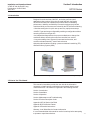 7
7
-
 8
8
-
 9
9
-
 10
10
-
 11
11
-
 12
12
-
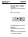 13
13
-
 14
14
-
 15
15
-
 16
16
-
 17
17
-
 18
18
-
 19
19
-
 20
20
-
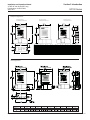 21
21
-
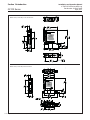 22
22
-
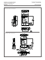 23
23
-
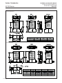 24
24
-
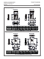 25
25
-
 26
26
-
 27
27
-
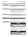 28
28
-
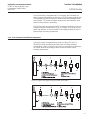 29
29
-
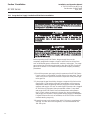 30
30
-
 31
31
-
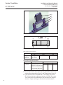 32
32
-
 33
33
-
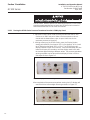 34
34
-
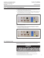 35
35
-
 36
36
-
 37
37
-
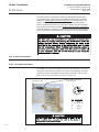 38
38
-
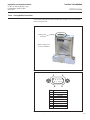 39
39
-
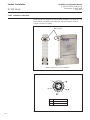 40
40
-
 41
41
-
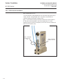 42
42
-
 43
43
-
 44
44
-
 45
45
-
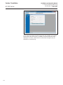 46
46
-
 47
47
-
 48
48
-
 49
49
-
 50
50
-
 51
51
-
 52
52
-
 53
53
-
 54
54
-
 55
55
-
 56
56
-
 57
57
-
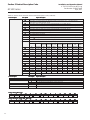 58
58
-
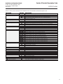 59
59
-
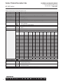 60
60
-
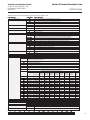 61
61
-
 62
62
-
 63
63
-
 64
64
-
 65
65
-
 66
66
-
 67
67
-
 68
68
-
 69
69
-
 70
70
-
 71
71
-
 72
72
-
 73
73
-
 74
74
-
 75
75
-
 76
76
-
 77
77
-
 78
78
-
 79
79
-
 80
80
-
 81
81
-
 82
82
-
 83
83
-
 84
84
-
 85
85
-
 86
86
-
 87
87
-
 88
88
-
 89
89
-
 90
90


Brooks GF100 / GF101 / GF120 / GF120XSL / GF120XSD / GF121 Instrucțiuni de utilizare
- Tip
- Instrucțiuni de utilizare
- Acest manual este potrivit și pentru
în alte limbi
Lucrări înrudite
-
Brooks GF80 Instrucțiuni de utilizare
-
 Brooks 9861 Instrucțiuni de utilizare
-
 Brooks VDM300 Instrucțiuni de utilizare
-
 Brooks GF40 Instrucțiuni de utilizare
-
 Brooks SLA585 Instrucțiuni de utilizare
-
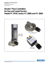 Brooks FC8744 / FC8800 / FC8900 Instrucțiuni de utilizare
-
 Brooks SLA5850 Instrucțiuni de utilizare
-
 Brooks 5700 Instrucțiuni de utilizare
-
 Brooks 4850 Instrucțiuni de utilizare
-
 Brooks 0254 Instrucțiuni de utilizare


Alte documente
-
Hach POLYMETRON 8312 Manual de utilizare
-
 Hach CLT10sc Manual de utilizare
-
 Hach ORBISPHERE 6110 Manual de utilizare
-
 Hach 29971-72 Manual de utilizare
-
RIDGID micro CD-100 Manual de utilizare
-
Facom DL.30T Manualul proprietarului
-
IDEAL STANDARD T5267 Manual de utilizare
-
Sames Cyclomix Micro / Micro+ / Micro+ PH / Micro+ PH+ Manual de utilizare
-
-


