
Brooks
®
GF80/GF81 Devices
Installation and Operation Manual
X-TMF-GF80-GF81-Series-MFC-eng
Part Number: 541B196AAG
September, 2014
Brooks
®
GF80/GF81 Series
MultiFlo
TM
Capable
Digital Thermal Mass Flow Devices
Brooks
®
GF80/GF81 Series available with RS485, DeviceNet
TM
, Profibus
®
or EtherCAT
®
I/O

Installation and Operation Manual
X-TMF-GF80-GF81-Series-MFC-eng
Part Number: 541B196AAG
September, 2014
Brooks
®
GF80/GF81 Devices

Brooks
®
GF80/GF81 Devices
Installation and Operation Manual
X-TMF-GF80-GF81-Series-MFC-eng
Part Number: 541B196AAG
September, 2014
Dear Customer,
We appreciate this opportunity to service your flow measurement and control requirements with a Brooks
Instrument device. Every day, flow customers all over the world turn to Brooks Instrument for solutions to their gas
and liquid low-flow applications. Brooks provides an array of flow measurement and control products for various
industries from biopharmaceuticals, oil and gas, fuel cell research and chemicals, to medical devices, analytical
instrumentation, semiconductor manufacturing, and more.
The Brooks product you have just received is of the highest quality available, offering superior performance,
reliability and value to the user. It is designed with the ever changing process conditions, accuracy requirements
and hostile process environments in mind to provide you with a lifetime of dependable service.
We recommend that you read this manual in its entirety. Should you require any additional information concerning
Brooks products and services, please contact your local Brooks Sales and Service Office listed on the back cover
of this manual or visit www.BrooksInstrument.com.
Yours sincerely,
Brooks Instrument

Installation and Operation Manual
X-TMF-GF80-GF81-Series-MFC-eng
Part Number: 541B196AAG
September, 2014
Brooks
®
GF80/GF81 Devices
THIS PAGE WAS
INTENTIONALLY
LEFT BLANK

i
Brooks
®
GF80/GF81 Devices
Installation and Operation Manual
X-TMF-GF80-GF81-Series-MFC-eng
Part Number: 541B196AAG
September, 2014
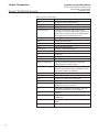
Contents
Paragraph Page
Number Number
Section 1 Introduction
1-1 Introduction ................................................................................................................................... 1-1
1-2 How to Use This Manual ................................................................................................................ 1-1
1-3 Product Support References ......................................................................................................... 1-2
1-4 Warning, Caution and Notice Statements ...................................................................................... 1-2
1-5 Product Warranty .......................................................................................................................... 1-2
1-6 How to Order a GF80/GF81 Series Device.................................................................................... 1-2
1-7 Industry Standard References .......................................................................................................1-2
1-8 GF80 Series Gas Table.................................................................................................................. 1-3
1-9 Glossary of Terms and Acronyms .................................................................................................. 1-3
1-10 Description .................................................................................................................................... 1-5
1-10 Product Description for GF81 Devices ..........................................................................................1-7
1-11 Specifications for GF80/GF81 Series Devices .............................................................................. 1-7
Section 2 Installation
2-1 General..........................................................................................................................................2-1
2-2 Receipt of Equipment .................................................................................................................... 2-1
2-3 Recommended Storage Practice ................................................................................................... 2-2
2-4 Return Shipment ............................................................................................................................ 2-2
2-5 Transit Precautions........................................................................................................................ 2-2
2-6 Removal from Storage ...................................................................................................................2-2
2-7 Gas Connections ........................................................................................................................... 2-3
2-8 In-Line Filter ..................................................................................................................................2-3
2-9 Mechanical Installation ..................................................................................................................2-3
2-10 Flow Controller Installation Arrangement ........................................................................................ 2-4
2-11 Purge the Gas Supply Line Before GF80/GF81 Series Installation................................................ 2-5
2-12 Position and Mount the GF80/GF81 Series ................................................................................... 2-6
2-13 Perform a Leak Test ...................................................................................................................... 2-6
2-14 Performance Checks.....................................................................................................................2-6
2-15 Zeroing Setup Process .................................................................................................................. 2-6
2-16 Zeroing the GF80/GF81 Series......................................................................................................2-7
2-17 Auto Shut-Off................................................................................................................................. 2-7
2-18 Using the MultiFlo
TM
Configurator .................................................................................................. 2-8
2-19 Electrical Connections.................................................................................................................. 2-10
2-19-1 DeviceNet Connections ................................................................................................................ 2-10
2-19-2 Analog/RS485 Connector ............................................................................................................. 2-11
2-19-3 Profibus Connections ................................................................................................................... 2-12
2-19-4 EtherCAT Connections ................................................................................................................. 2-12
2-19-5 Alarm Output (Analog I/O Version Only) ....................................................................................... 2-13
Section 3 Operation
3-1 General..........................................................................................................................................3-1
3-2 Theory of Operation for Flow Measurement................................................................................... 3-1
Section 4 Maintenance & Troubleshooting
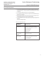
4-1 Overview ........................................................................................................................................ 4-1
4-2 Maintenance .................................................................................................................................. 4-1
4-3 Troubleshooting ............................................................................................................................. 4-2
4-4 Troubleshooting Checklist .............................................................................................................. 4-3
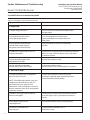
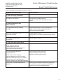
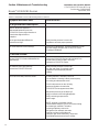
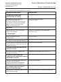
4-5 GF80/GF81 Series Troubleshooting Guide .................................................................................... 4-4
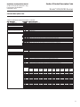
Section 5 Product Description Code ......................................................................................................5-1

ii
Brooks
®
GF80/GF81 Devices
Installation and Operation Manual
X-TMF-GF80-GF81-Series-MFC-eng
Part Number: 541B196AAG
September, 2014
Contents
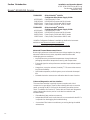
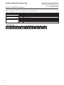
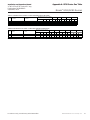
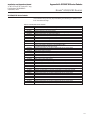
Appendix A: GF80 Series Gas Table .......................................................................................................A-1
Appendix B: GF80/GF81 Series Patents................................................................................................B-1
Appendix C: Essential Instructions ....................................................................................................... C-1
Warranty, Local Sales/Service Contact Information....................................................................... Back Cover
Figure Page
Number Number
1-1 GF80/GF81 Series Digital Thermal Mass Flow Devices................................................................. 1-1
1-2 Dimensions - GF80 Series ........................................................................................................... 1-10
1-3 Dimensions - GF81 Series ........................................................................................................... 1-10
2-1 Typical Gas Supply Arrangement................................................................................................... 2-4
2-2 Zero Button Accessible at Top of Device ....................................................................................... 2-7
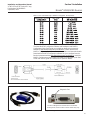
2-3 MultiFlo Cable Adapter...................................................................................................................2-9
2-4 RS485-USB Converter (P/N 214F027AAA) ................................................................................... 2-9
2-5 Diagnostic Port.............................................................................................................................. 2-9
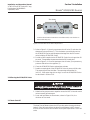
2-6 GF80/GF81 Series DeviceNet Connection and Pin-Outs.............................................................. 2-10
2-7 GF80/GF81 Series with 15-Pin Analog Connector and Pin-Outs.................................................. 2-11
2-8 GF80/GF81 Series Profibus Connections and Pin-Outs...............................................................2-12
2-9 GF80 Series EtherCAT Connections and Pin-Outs ......................................................................2-12
2-10 Alarm Output Schematic ...............................................................................................................2-13
3-1 GF80/GF81 Series Operating Principles ....................................................................................... 3-2
Table Page
Number Number
1-1 Industry Standard References .......................................................................................................1-3
1-2 Terms and Acronyms ..................................................................................................................... 1-4
1-3 Specifications for Standard GF80/GF81 Series............................................................................. 1-8
1-4 Electrical Specifications for GF80/GF81 Series ............................................................................ 1-9
2-1 Gas and Flow Ranges - MultiFlo Configurable - N2 Equivalent ..................................................... 2-10
4-1 Environmental Factors ................................................................................................................... 4-3
4-2 GF80/GF81 Series Troubleshooting Guide .................................................................................... 4-4
5-1 GF80 Series Product Description Code Table ............................................................................... 5-1
5-2 GF81 Series Product Description Code Table ............................................................................... 5-3
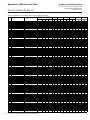
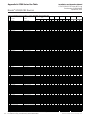
A-1 GF80 Series Gas Table - Codes 1-94, Bins SA40 to SA44 ...........................................................A-1
A-2 GF80 Series Gas Table - Codes 1-94, Bins SA45 to SA50 ...........................................................A-2
A-3 GF80 Series Gas Table - Codes 97-606, Bins SA40 to SA44 .......................................................A-3
A-4 GF80 Series Gas Table - Codes 97-606, Bins SA45 to SA50 .......................................................A-4
A-5 GF80 Series Gas Table - Codes 607-926, Bins SA40 to SA44 .....................................................A-5
A-6 GF80 Series Gas Table - Codes 607-926, Bins SA45 to SA50 .....................................................A-6
A-7 GF80 Series Gas Table - Codes 927-5022, Bins SA40 to SA44 ...................................................A-7
A-8 GF80 Series Gas Table - Codes 927-5022, Bins SA45 to SA50 ...................................................A-8
B-1 GF80/GF81 Series Patents............................................................................................................B-1

1-1
Brooks
®
GF80/GF81 Devices
Installation and Operation Manual
X-TMF-GF80-GF81-Series-MFC-eng
Part Number: 541B196AAG
September, 2014
Section 1 Introduction
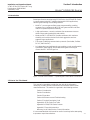
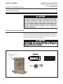
1-1 Introduction
Based upon Brooks award-winning GF100 Series, the GF80/GF81 Series
is a performance/value MFC platform designed for OEM applications,
delivering the following class leading features:
• MultiFlo™ process gas and flow range programmability, enabling
customers to re-configure the MFC for new gases and full scale flow
rates for unparalleled process flexibility.
• A high-performance, corrosion-resistant flow measurement sensor
delivers improved reproducibility and stability.
• Metal seal MFCs (GF80/GF81) provide customers with maximum
durability and corrosion resistance for both aggressive and non-
aggressive gas applications.
• Full range of industrial communication protocols (DeviceNet, Profibus
DP-V1, and EtherCAT).
• An independent service/diagnostic port enables on-tool reconfiguration/
optimization, data logging, and troubleshooting without having to
remove the MFC from the gas line.
Figure 1-1 GF80 Series MultiFlo
TM
Capable Digital Thermal Mass Flow Devices
1-2 How to Use This Manual
This manual is intended to provide the user with all the information
necessary to install, operate, troubleshoot and maintain these thermal
mass flow devices. The manual is organized in the following sections:
Section 1 Introduction
Section 2 Installation
Section 3 Operation
Section 4 Maintenance and Troubleshooting
Section 5 Product Description Code
Appendix A GF80 Series Gas Table
Appendix B GF80/GF81 Series Patents
Appendix C Essential Instructions
Warranty, Local Sales/Service Contact Information
It is recommended that this manual be read in its entirety before attempting
to operate or repair these devices.

1-2
Brooks
®
GF80/GF81 Devices
Installation and Operation Manual
X-TMF-GF80-GF81-Series-MFC-eng
Part Number: 541B196AAG
September, 2014
Section 1 Introduction
1-3 Product Support References
Refer to www.BrooksInstrument.com for Brooks sales and service
locations and to obtain other documents that support the GF80/GF81
Series. Those documents include:
• Brooks MultiFlo
TM
Configurator Quick Start Manual
(X-SW-MultiFlo-Config-QS-eng; part number 541B167AAG)
• Brooks GF80/GF81 Series data sheet (DS-TMF-GF80-GF81-Series-
MFC-eng)
• DeviceNet
TM
Supplemental Manual for GF40/GF80/GF81 Series Mass
Flow Controllers and Meters
(X-DPT-DeviceNet-GF40-GF80-MFC-eng; part number 541B168AAG)
• Profibus
®
Supplemental Manual for Brooks
®
GF40/GF80/GF81 Series
Mass Flow Controllers and Meters
(X-DPT-Profibus-GF40-GF80-MFC-eng; part number 541B162AAG)
• RS485 Supplemental Manual for GF40/GF80/GF81 Series Mass Flow
Controllers and Meters
(X-DPT-RS485-GF40-GF80-MFC-eng; part number 541B169AAG)
• EtherCAT Supplemental Manual for Brooks
®
GF40/GF80 Series Mass
Flow Controllers and Meters
(X-DPT-EtherCAT-GF40-GF80-MFC-eng; part number 541B170AAG)
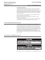
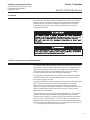
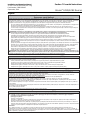
1-4 Warning, Caution and Notice Statements
Warning, caution and notice statements are located throughout this manual
in the ANSI format. A WARNING statement indicates a potentially
hazardous situation which, if not avoided, COULD result in death or serious
injury. A CAUTION statement indicates a potentially hazardous situation
which, if not avoided, MAY result in minor or moderate injury. It may also be
used to alert against unsafe practices. A NOTICE statement describes
specific information that requires special attention.
1-5 Product Warranty
Product warranty information can be found on the Back Cover of this
Manual and on the Brooks website at www.BrooksInstrument.com. This
information provides general warranty information, limitations, disclaimers,
and applicable warranty periods according to product group.
1-6 How to Order a GF80/GF81 Series Device
Refer to Section 5.

1-3
Brooks
®
GF80/GF81 Devices
Installation and Operation Manual
X-TMF-GF80-GF81-Series-MFC-eng
Part Number: 541B196AAG
September, 2014
Section 1 Introduction
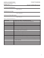
Table 1-1 Industry Standard References
Reference Number Reference Description
MIL-STD-810 Method 514.4, Category 1, Transportation Requirement
Method 516.4, Procedure 1, Functional Shock Test Requirement
SEMI E12 Standard temperature and pressure
SEMI E16 Guideline for determining and describing MFC leak rates
SEMI E17 Guideline for MFC transient characteristics tests
SEMI E18 Guideline for temperature specifications of the MFC
SEMI E27 Standard for MFC and MFM linearity
SEMI E28 Guideline for pressure specifications for the MFC
SEMI E52 Practice for referencing gases used in digital MFCs
SEMI E54 Sensor actuator network connections for DeviceNet
SEMI E56 Test method for detemining accuracy, linearity, repeatability, short-term
reproducibility, hystereses of thermal MFCs
SEMI E66 Test method for determining particle contribution by MFCs
SEMI E67 Test method for determining reliabilty of MFCs
SEMI E68 Test method for determining warm-up time of MFCs
SEMI E69 Test method for reproducibilty and zero drift for thermal MFCs
SEMI E80 Test method for determining attitude sensitivity of MFCs
SEMI E16-90 Guidelines for determining and describing mass flow controllers leak rates
SEMI F36 Guide for dimensions and connections of gas distribution components
SEMI F44 Guideline for standardization of machined stainless steel weld fittings
SEMI F45 Guideline for standardization of machined stainless steel reducing fittings
SEMI F47 Specifications for semiconductor processing equipment
voltage sag immunity
SEMI S2 Environmental, Health and Safety Guidelines
SEMI S9 Dielectric testing
SEMI S10 Risk assessment
SEMI S12 Decontamination of fielded products
1-7 Industry Standard References
Refer to Table 1-1.
1-8 GF80 Devices Gas Table
Refer to Appendix A.
1-9 Glossary of Terms and Acronyms
Refer to Table 1-2

1-4
Brooks
®
GF80/GF81 Devices
Installation and Operation Manual
X-TMF-GF80-GF81-Series-MFC-eng
Part Number: 541B196AAG
September, 2014
Section 1 Introduction
Term or Acronym Definition
CSR Customer Special Requirement.
CVD Chemical Vapor Deposition.
DSP Digital Signal Processor.
EPI Epitaxy (EPI). A process technology where a pure silicon
crystalline structure is deposited or “grown” on a
bare wafer, enabling a high-purity starting point
for building the semiconductor device.
HBD Horizontal Base Down.
HLD Horizontal Label Down.
HLU Horizontal Label Up.
HUD Horizontal Upside Down.
GF80 Series MultiFlo capable digital device.
GF81 Series High Flow Digital Device.
F.S. Full Scale.
LED Light Emitting Diode.
MFC Mass Flow Controller.
MultiFlo Configurator I/O communication software package that
configures gas and flow ranges.
MultiFlo Technology A physics-based calibration methodology that
enables gas and flow range configuration within
a defined standard configuration.
PID Proportional Integral Derivative Controller.
PSIA Pounds per Square Inch Absolute.
PSID Pounds per Square Inch Differential.
PSIG Pounds per Square Inch Gauge.
ROR As pressure increases, flow increases at a
pressure rate of rise, or ROR.
HC Standard Configuration w/ Hastelloy
®
sensors
(to reduce reaction to corrosive gases).
S.P. Setpoint.
Step Technology Enables fast set point control through a high
speed DSP.
VID Vertical mounting attitude with inlet side facing
down.
VIU Vertical mounting attitude with inlet side facing up.
Table 1-2 Terms and Acronyms

1-5
Brooks
®
GF80/GF81 Devices
Installation and Operation Manual
X-TMF-GF80-GF81-Series-MFC-eng
Part Number: 541B196AAG
September, 2014
Section 1 Introduction
1-10 Description
Control
The GF80/GF81 Series brings together Brooks high-performance,
patented ultra-fast T-rise flow sensor, high-speed ARM based digital
architecture, and a fast-acting diaphragm-free solenoid valve to deliver:
• Fast reproducible transitions between setpoints without overshoot or
ringing
• User-programmable ramp functions for processes requiring a slow-
ramp in flow or time critical transitions
MultiFlo™ Gas and Range Configurability
The Brooks MultiFlo technology delivers exceptional improvement in
process gas accuracy for linear and non-linear gases. This is achieved
through advanced gas modeling and optimized through actual gas testing.
Brooks MultiFlo
TM
allows the device to be quickly and easily configured for
another gas and/or flow range without sacrificing accuracy or rangability.
Selecting a new gas automatically creates a new calibration curve,
establishes optimized PID settings for dynamic control, automatically
compensates for gas density effects, and ensures smooth overshoot-free
transitions between flow rates with excellent steady-state stability. Brooks
MultiFlo technology offers unparalleled flexibility. An extensive gas
database is provided and a single device can be quickly programmed for
thousands of different gas and flow range combinations. Process benefits
achieved include:
• Mass flow controller full scale full range can be rescaled down typically
by a factor of 3:1 with no impact on accuracy, turndown or leak by
specifications
• Optimum process and inventory flexibility resulting in dramatically
reduced inventory costs
• Fewer configurations/bin sizes required to support many different
processes
• Less down-time with rapid process recovery
MultiFlo
TM
Support References: Brooks MultiFlow Configurator Quick
Start Guide (X-SW-MultiFlo-Config-QS-eng [Part Number: 541B167AAG])
MultiFlo
TM
Configurator Accessory Kits:
MultiFlo kits are available in the following configurations:
778Z010ZZZ Basic MultiFlo Configurator Kit
A331710003 Cable Assembly 2.5mm
214F027AAA USB-RS485 converter with DB-9 female
778Z012ZZZ GF0xx RS485 Analog/Profibus
®
MultiFlo
Configurator Kit w/Power Supply 24 Vdc
A331710003 Cable Assembly 2.5mm
214F027AAA USB-RS485 converter with DB-9 female
641Z117AAA Power Supply 24 Vdc with DB-15 female

1-6
Brooks
®
GF80/GF81 Devices
Installation and Operation Manual
X-TMF-GF80-GF81-Series-MFC-eng
Part Number: 541B196AAG
September, 2014
Section 1 Introduction
778Z013ZZZ GF0xx EtherCAT
®
MultiFlo
Configurator Kit w/Power Supply 24 Vdc
A331710003 Cable Assembly 2.5mm
214F027AAA USB-RS485 converter with DB-9 female
641Z117AAA Power Supply 24 Vdc with DB-15 female
124Z170AAA Cable, Power, EtherCAT to DB-15 male
778Z014ZZZ GF0xx DeviceNet
TM
MultiFlo
Configurator Kit w/Power Supply 24 Vdc
A331710003 Cable Assembly 2.5mm
214F027AAA USB-RS485 converter with DB-9 female
641Z117AAA Power Supply 24 Vdc with DB-15 female
124Z171AAA Cable, Power, DeviceNet to DB-15 male
* MultiFlo Configurator Software is available on the Brooks Instrument
website at: www.BrooksInstrument.com/MultiFlo
www.BrooksInstrument.com/Documentation&Downloads
Advanced Thermal Measurement Sensor
Brooks high-performance thermal flow sensor brings together key design
elements to deliver the accurate, repeatable measurement under
challenging process conditions:
• Improved accuracy at elevated temperatures through isothermal
packaging and ambient temperature sensing and compensation
• Enhanced signal-to-noise performance enables improved low setpoint
accuracy
• A large bore, corrosion resistant, Hastelloy
®
C-22 sensor tube ensures
long life and reliability
• Optimized temperature profile for gases prone to thermal decomposi-
tion
• Onboard electronics store sensor calibration data for ease of service
Enhanced Diagnostics and User Interface
The mass flow controller is typically the most complex and critical
component in a gas delivery system, When dealing with toxic or reactive
gases, removing the MFC to access its functionality should be the last
resort. To address this, Brooks GF Series devices include self-diagnostics
and an independent service port for in-situ device evaluation and
troubleshooting:
• Embedded self-test routines at power-up
• Independent RS485 service port that can be accessed while the MFC is
in operation for data logging and troubleshooting
• A convenient Zero button to enable easy re-zeroing during scheduled
maintenance

1-7
Brooks
®
GF80/GF81 Devices
Installation and Operation Manual
X-TMF-GF80-GF81-Series-MFC-eng
Part Number: 541B196AAG
September, 2014
Section 1 Introduction
Communication Interfaces
The GF80/GF81 Series supports 0-5 Vdc, 0-10 Vdc, 4-20 mA, 0-20 mA,
RS485, DeviceNet, EtherCAT, and Profibus communication protocols.
DeviceNet, Profibus, EtherCAT and RS485 are multi-drop connections that
allow a maximum of 64 devices for DeviceNet, 128 devices for Profibus,
32 devices for RS485, and 65,535 devices for EtherCAT to be connected
on the same network.
Brooks Instruments' DeviceNet profile has been certified by the ODVA
(Open DeviceNet Vendor's Association).
Brooks Instrument Profibus interface has been certified by the PNO
(Profibus User Organization).
The Brooks Instrument EtherCAT interface has been successfully tested
by the EtherCAT Conformance Test application version 1.20.30.0.
1-11 Product Description for GF81 Series Devices
The Brooks GF81 Series is a high flow version of the GF80 featuring a
corrosion-resistant Hastelloy C-22 for durable, long term operation. Sub-1
second settling times and 1% of reading accuracy ensures that the GF81
will provide reliable flow measurement or control in demanding gas flow
applications. The GF81 achieves excellent internal to external leak integrity
for challenging process gases as found in CVD, solar, and other
processes. With a wide range of digital and analog I/O options available,
the GF81 represents an extremely powerful, yet easy, upgrade for existing
MFCs or MFMs.
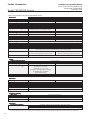
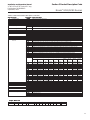
1-12 Specifications for GF80/GF81 Series Devices
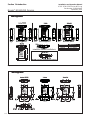
See Tables 1-3 thru 1-5 for specifications for the GF80/GF81 Series.
See Figures 1-2 thru 1-4 for dimensions for the GF80/GF81 Series.

1-8
Brooks
®
GF80/GF81 Devices
Installation and Operation Manual
X-TMF-GF80-GF81-Series-MFC-eng
Part Number: 541B196AAG
September, 2014
Section 1 Introduction
Table 1-3 Specifications for Standard GF80/GF81 Series
GF80GF80
GF80GF80
GF80
GF81GF81
GF81GF81
GF81
MecMec
MecMec
Mec
hanicalhanical
hanicalhanical
hanical
VV
VV
V
alve alve
alve alve
alve
TT
TT
T
ypeype
ypeype
ype Normally Closed, No Valve (Meter) Normally Closed, Meter
Primary Primary
Primary Primary
Primary
WW
WW
W
etted Materialsetted Materials
etted Materialsetted Materials
etted Materials 316 Stainless Steel, Hastelloy C-22, 17-7 PH, 430SS 316 Stainless Steel, Hastelloy C-22, KM45
External SealsExternal Seals
External SealsExternal Seals
External Seals 316 Stainless Steel
InIn
InIn
In
ternal Seals/Vternal Seals/V
ternal Seals/Vternal Seals/V
ternal Seals/V
alve Seatalve Seat
alve Seatalve Seat
alve Seat 316 Stainless Steel
Surface FinishSurface Finish
Surface FinishSurface Finish
Surface Finish 16μ inch Ra
PP
PP
P
erformanceerformance
erformanceerformance
erformance
Full Scale Flow Range (NFull Scale Flow Range (N
Full Scale Flow Range (NFull Scale Flow Range (N
Full Scale Flow Range (N
22
22
2
Eq.) Eq.)
Eq.) Eq.)
Eq.) 3 sccm to 55 slm 51 - 300 slm
Flow Flow
Flow Flow
Flow
AccurAccur
AccurAccur
Accur
acyacy
acyacy
acy +1% S.P. 35-100%, +0.35% F.S. 2-35% +1% S.P. 35-100% , +0.35% F.S. 5-35%
Repeatability & ReprRepeatability & Repr
Repeatability & ReprRepeatability & Repr
Repeatability & Repr
oducibilityoducibility
oducibilityoducibility
oducibility <
+ 0.2% S.P. 0.15% S.P.
LinearityLinearity
LinearityLinearity
Linearity + 0.5% F.S. (included in accuracy)
Response Response
Response Response
Response
Time (Settling Time (Settling
Time (Settling Time (Settling
Time (Settling
Time)Time)
Time)Time)
Time) Normally Closed Valve < 1 sec. < 1 second
(within 2% for steps 0-10 through 0-100%)
ConCon
ConCon
Con
trtr
trtr
tr
ol Rangeol Range
ol Rangeol Range
ol Range 2-100% 5% - 100%
MultiFloMultiFlo
MultiFloMultiFlo
MultiFlo optional N/A
Number of BinsNumber of Bins
Number of BinsNumber of Bins
Number of Bins 11 bins 4 bins
VV
VV
V
alve Shut Downalve Shut Down
alve Shut Downalve Shut Down
alve Shut Down < 1% of F.S. <2% of Standard Configuration F.S. @ 30 N
2
psig/atm out
ZZ
ZZ
Z
erer
erer
er
o Stabilityo Stability
o Stabilityo Stability
o Stability < + 0.5% F.S. per year
PrPr
PrPr
Pr
essuressur
essuressur
essur
e Coefficiene Coefficien
e Coefficiene Coefficien
e Coefficien
tt
tt
t 0.03% per psi (0-50psi N
2
)
AA
AA
A
ttitude Sensitivityttitude Sensitivity
ttitude Sensitivityttitude Sensitivity
ttitude Sensitivity <0.25% span change @ 90
O
after rezeroing (N
2
@ 50 psi)
Auto ZAuto Z
Auto ZAuto Z
Auto Z
erer
erer
er
o:o:
o:o:
o: Optional: (When Auto Zero is enabled the device performs the zero function once every time
the set point returns to zero. To accomplish, simply provide a zero set point.)
Auto shut-off:Auto shut-off:
Auto shut-off:Auto shut-off:
Auto shut-off: The Auto Shut-off feature closes the GF80 valve The Auto Shut-off feature closes the GF81 valve
when the set point drops below 1.5% of full scale when the set point drops below 2% of full scale.
AA
AA
A
vailable Gases:vailable Gases:
vailable Gases:vailable Gases:
vailable Gases: MultiFlo Capable N
2
, H
2
, Ar, He, O
2
, NH
3
(consult factory for other gases)
RatingsRatings
RatingsRatings
Ratings
OperOper
OperOper
Oper
ating ating
ating ating
ating
TT
TT
T
emperemper
emperemper
emper
aturatur
aturatur
atur
e Rangee Range
e Rangee Range
e Range 5-50
O
C (41-122
O
F)
Maximum OperMaximum Oper
Maximum OperMaximum Oper
Maximum Oper
ating Prating Pr
ating Prating Pr
ating Pr
essuressur
essuressur
essur
e*e*
e*e*
e* 150 psig (10 bar) Controller: 75 psig (5 bar) / Meter: 150 psig (10 bar)
DifferDiffer
DifferDiffer
Differ
enen
enen
en
tial Prtial Pr
tial Prtial Pr
tial Pr
essuressur
essuressur
essur
e Range*e Range*
e Range*e Range*
e Range* 3-860 sccm = 7-45 psid, 30 - 90 psid
861-7200 sccm = 15-45 psid,
7201-50000 sccm = 25-45 psid
Typical pressure drop, high density gases like Argon
gas applications require an additional
10 psid differential pressure
Leak InLeak In
Leak InLeak In
Leak In
tegrity (External)tegrity (External)
tegrity (External)tegrity (External)
tegrity (External) 1x10
-10
atm. cc/sec He
Diagnostics & DisplayDiagnostics & Display
Diagnostics & DisplayDiagnostics & Display
Diagnostics & Display
Status Lights:Status Lights:
Status Lights:Status Lights:
Status Lights: MFC Health, Network Status
Alarms*:Alarms*:
Alarms*:Alarms*:
Alarms*: Sensor Output, Control Valve Output, Over Temperature, Power Surge/Sag, Network Interruption
Diagnostic / Service PDiagnostic / Service P
Diagnostic / Service PDiagnostic / Service P
Diagnostic / Service P
ort:ort:
ort:ort:
ort: RS485 via 2.5mm jack
* Note: Application specific lower supply pressure and/or lower differential pressure operation available through Brooks Customer Special Request (CSR) process.
ComplianceCompliance
ComplianceCompliance
Compliance
EnEn
EnEn
En
virvir
virvir
vir
onmenonmen
onmenonmen
onmen
tal Compliance:tal Compliance:
tal Compliance:tal Compliance:
tal Compliance: CE: EN6126: 2006 (FCC Part 15 & Canada IC-subset of CE testing)
Safety EN61010-1
RoHS

1-9
Brooks
®
GF80/GF81 Devices
Installation and Operation Manual
X-TMF-GF80-GF81-Series-MFC-eng
Part Number: 541B196AAG
September, 2014
Section 1 Introduction
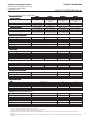
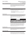
Table 1-4 GF80/GF81 Electrical Specifications
Communication PrCommunication Pr
Communication PrCommunication Pr
Communication Pr
otocolotocol
otocolotocol
otocol
RS485*RS485*
RS485*RS485*
RS485*
PrPr
PrPr
Pr
ofibusofibus
ofibusofibus
ofibus
®®
®®
®
DeviceNetDeviceNet
DeviceNetDeviceNet
DeviceNet
TMTM
TMTM
TM
EtherCAEtherCA
EtherCAEtherCA
EtherCA
TT
TT
T
®®
®®
®
Electrical ConnectionElectrical Connection
Electrical ConnectionElectrical Connection
Electrical Connection 1 x 15-pin Male Sub-D, 1 x 15-pin Male Sub-D/ 1 x M12 with 5-pin M8 with
(A) 1 x 9-pin Female threaded coupling nut threaded coupling nut/
Sub-D (B) 2 x RJ45
Analog I/OAnalog I/O
Analog I/OAnalog I/O
Analog I/O 0-5 V, 0-10 V, 0-5 V, 0-20 mA, 0-5 V
0-20 mA, 4-20 mA 4-20 mA
GF80 PGF80 P
GF80 PGF80 P
GF80 P
ower Max./Purower Max./Pur
ower Max./Purower Max./Pur
ower Max./Pur
gege
gege
ge From +12 Vdc to From +13.5 Vdc to From +11 Vdc to From +13.5 Vdc to
+24 Vdc: 7 Watt/8 Watt +27 Vdc: 7 Watt/8 Watt +25 Vdc: 13.6 Watt/15.0Watt +27 Vdc: 7 Watt/8 Watt
GF81 PGF81 P
GF81 PGF81 P
GF81 P
ower Max./Purower Max./Pur
ower Max./Purower Max./Pur
ower Max./Pur
gege
gege
ge From +12 Vdc to From +13.5 Vdc to From +11 Vdc to N/A
N/A +24 Vdc: 3.3 Watt/10.2 Watt +27 Vdc: 3.3 Watt/10.2 Watt +25 Vdc: 3.3 Watt/10.2 Watt
VV
VV
V
oltage Set Poltage Set P
oltage Set Poltage Set P
oltage Set P
oinoin
oinoin
oin
t Input Specificationt Input Specification
t Input Specificationt Input Specification
t Input Specification
Nominal RangeNominal Range
Nominal RangeNominal Range
Nominal Range 0-5 Vdc or 0-10 Vdc 0-5 Vdc N/A N/A
Full RangeFull Range
Full RangeFull Range
Full Range 0-11 Vdc 0-5.5 Vdc N/A N/A
Absolute Max.Absolute Max.
Absolute Max.Absolute Max.
Absolute Max. 25 V (without damage) N/A N/A
Input ImpedenceInput Impedence
Input ImpedenceInput Impedence
Input Impedence 192 kOhms N/A N/A
RequirRequir
RequirRequir
Requir
ed Max. Sink Curred Max. Sink Curr
ed Max. Sink Curred Max. Sink Curr
ed Max. Sink Curr
enen
enen
en
tt
tt
t 0.002 mA N/A N/A
CurrCurr
CurrCurr
Curr
enen
enen
en
t Set Pt Set P
t Set Pt Set P
t Set P
oinoin
oinoin
oin
tt
tt
t
Nominal RangeNominal Range
Nominal RangeNominal Range
Nominal Range 4-20 mA or 0-20 mA N/A N/A
Full RangeFull Range
Full RangeFull Range
Full Range 0-22 mA N/A N/A
Absolute Max.Absolute Max.
Absolute Max.Absolute Max.
Absolute Max. 25 mA (without damage) N/A N/A
Input ImpedenceInput Impedence
Input ImpedenceInput Impedence
Input Impedence 250 Ohms 125 Ohms N/A N/A
Flow Output (VFlow Output (V
Flow Output (VFlow Output (V
Flow Output (V
oltage) Specificationsoltage) Specifications
oltage) Specificationsoltage) Specifications
oltage) Specifications
Nominal RangeNominal Range
Nominal RangeNominal Range
Nominal Range 0-5 Vdc or 0-10 Vdc 0-5 Vdc N/A 0-5 Vdc
Full RangeFull Range
Full RangeFull Range
Full Range (-0.5)-11 Vdc 0-5.5 Vdc - (-0.5)-5.5 Vdc
Min Load ResistanceMin Load Resistance
Min Load ResistanceMin Load Resistance
Min Load Resistance 1 kOhms 1 kOhms - 0.5 kOhms
Flow Output (CurrFlow Output (Curr
Flow Output (CurrFlow Output (Curr
Flow Output (Curr
enen
enen
en
t) Specificationst) Specifications
t) Specificationst) Specifications
t) Specifications
Nominal RangeNominal Range
Nominal RangeNominal Range
Nominal Range 0-20 mA or 4-20 mA N/A N/A
Full RangeFull Range
Full RangeFull Range
Full Range 0-22 mA (@ 0-20 mA); 3.8-22 mA (@ 4-20 mA) N/A N/A
Max. LoadMax. Load
Max. LoadMax. Load
Max. Load 400 Ohms (for supply voltage: 12-24 Vdc N/A N/A
Analog I/O Analog I/O
Analog I/O Analog I/O
Analog I/O
Alarm Ouput**Alarm Ouput**
Alarm Ouput**Alarm Ouput**
Alarm Ouput**
TT
TT
T
ypeype
ypeype
ype Open Collector N/A N/A
Max. Closed (On) CurrMax. Closed (On) Curr
Max. Closed (On) CurrMax. Closed (On) Curr
Max. Closed (On) Curr
enen
enen
en
tt
tt
t 25 mA N/A N/A
Max. Open (Off) LeakageMax. Open (Off) Leakage
Max. Open (Off) LeakageMax. Open (Off) Leakage
Max. Open (Off) Leakage 1μA N/A N/A
Max. Open (Off) Max. Open (Off)
Max. Open (Off) Max. Open (Off)
Max. Open (Off)
VV
VV
V
oltageoltage
oltageoltage
oltage 30 Vdc N/A N/A
Analog I/O Analog I/O
Analog I/O Analog I/O
Analog I/O
VV
VV
V
alve Override Signal Specifications***alve Override Signal Specifications***
alve Override Signal Specifications***alve Override Signal Specifications***
alve Override Signal Specifications***
Floating/UnconnectedFloating/Unconnected
Floating/UnconnectedFloating/Unconnected
Floating/Unconnected Instrument controls valve to command set point N/A N/A
VV
VV
V
OR < 1.40 OR < 1.40
OR < 1.40 OR < 1.40
OR < 1.40
VV
VV
V
dcdc
dcdc
dc Valve Closed N/A N/A
1.70 1.70
1.70 1.70
1.70
VV
VV
V
dc < dc <
dc < dc <
dc <
VV
VV
V
OR < 2.90 OR < 2.90
OR < 2.90 OR < 2.90
OR < 2.90
VV
VV
V
dcdc
dcdc
dc Valve Normal N/A N/A
VV
VV
V
OR > 3.20 OR > 3.20
OR > 3.20 OR > 3.20
OR > 3.20
VV
VV
V
dcdc
dcdc
dc Valve Open N/A N/A
Input ImpedenceInput Impedence
Input ImpedenceInput Impedence
Input Impedence 800 kOhms N/A N/A
Absolute Max. InputAbsolute Max. Input
Absolute Max. InputAbsolute Max. Input
Absolute Max. Input
(-25 Vdc) < VOR < 25 Vdc (without damage) N/A N/A
*There are three (3) RS485 Protocols:
S-Protocol is a RS485 communication based on HART
®
command set.
L-Protocol is a RS485 communication compatible with legacy Unit
®
and Celerity
®
devices.
A-Protocol is a RS485 communication compatible with Aera
®
mass flow devices.
**The Alarm Output is an open collector or "contact type" that is CLOSED (on) whenever an alarm is active. The Alarm Output may be set to indicate any one of various alarm
conditions.
*** The Valve Override Signal (VOR) is implemented as an analog input which measures the voltage at the input and controls the valve based upon the measured reading as shown in
this section.

1-10
Brooks
®
GF80/GF81 Devices
Installation and Operation Manual
X-TMF-GF80-GF81-Series-MFC-eng
Part Number: 541B196AAG
September, 2014
Section 1 Introduction
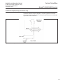
Figure 1-3 Dimensions - GF81 Series
Figure 1-2 Dimensions - GF80 Series
GF80 ConGF80 Con
GF80 ConGF80 Con
GF80 Con
figurfigur
figurfigur
figur
ationsations
ationsations
ations
GF81 ConGF81 Con
GF81 ConGF81 Con
GF81 Con
figurfigur
figurfigur
figur
ationsations
ationsations
ations

2-1
Brooks
®
GF80/GF81 Devices
Installation and Operation Manual
X-TMF-GF80-GF81-Series-MFC-eng
Part Number: 541B196AAG
September, 2014
Section 2 Installation
2-1 General
This section provides installation instructions for the Brooks GF80/GF81
Series Thermal Mass Flow Devices. The installation process consists of
purging the gas supply line prior to installation, unpacking and inspecting
the device, connecting the device to the gas supply line and testing for
leaks.
2-2 Receipt of Equipment
When the instrument is received, the outside packing case should be checked
for damage incurred during shipment. If the packing case is damaged, the local
carrier should be notified at once regarding their liability. A report should be
submitted to your nearest Product Service Department.
Americas: Asia, Japan:
Brooks Instrument Brooks Instrument
407 W. Vine Street 1-4-4 Kitsuna, Koto-ku
P.O. Box 903 Tokyo 136-0073
Hatfield, PA 19440 USA Japan
Toll Free (888) 554 FLOW (3569) Tel 81 (3) 5633-7104
Tel (215) 362 3700
Fax (215) 362 3745 Brooks Instrument Korea, Ltd.
E-mail: BrooksAm@BrooksInstrument.com D-406 Bundang Techno Park 151
www.BrooksInstrument.com Sungnam, Kyungki-do, 463-070
Korea
Europe, Middle East, Africa: Tel +82 31 708 2522
Brooks Instrument B.V.
Neonstraat 3, P.O. Box 428 Brooks Instrument (Shanghai) Co. LTD
6710 BX Ede RM 203, Bldg 6
Netherlands NO 1888 Xin Jin Qiao Rd
Tel +31 (0) 318 549292 or Jinqiao E.P.Z. Pudong
+31 (0) 318 549291 Shanghai 201206
E-mail: service.coordinator@Brooks Instrument.com China
Tel 86-21-3895-4788
Brooks Instrument GmbH
Zur Wetterwarte 50 Haus 377/B,
01109 Dresden
Germany
Tel +49 (0) 351 215 20 442
E-mail: service.coordinatorDD@Brooks Instrument.com
In case you need technical assistance:
USA 888 275 8946 Korea +82 31 708 2521
Netherlands +31 (0) 318 549290 Taiwan +886 3 5590 988
Germany +49 351 215 2040 China +86 21 5079 8828
Japan +81 3 5633 7100 Singapore +6297 9741

2-2
Brooks
®
GF80/GF81 Devices
Installation and Operation Manual
X-TMF-GF80-GF81-Series-MFC-eng
Part Number: 541B196AAG
September, 2014
Section 2 Installation
Remove the envelope containing the packing list. Outside of your clean area,
carefully remove the equipment from the packing case. Make sure spare
parts are not discarded with the packing material. Inspect the contents for
damaged or missing parts.
2-3 Recommended Storage Practice
If intermediate or long-term storage of the device is required, it is
recommended that it be stored in accordance with the following conditions:
• Within the original shipping container.
• Ambient temperature 21°C (70°F) nominal, 32°C (90°F) maximum,
7°C (45°F) minimum.
• Relative humidity 45% nominal, 60% maximum, 25% minimum.
2-4 Return Shipment
Prior to returning any device to the factory, visit the Brooks web site
(www.BrooksInstrument.com) for a Return Materials Authorization Number
(RMA#), or contact one of the locations provided on p. 2-1.
Prior to returning the device, it must be purged in accordance with the
following:
All flow devices returned to Brooks require completion of Form RPR003-2,
Brooks Instrument Decontamination Statement, along with a Material
Safety Data Sheet (MSDS) for the fluid(s) used in the instrument. Failure
to provide this information will delay processing by Brooks personnel.
Copies of these forms can be downloaded from the Brooks website
(www.BrooksInstrument.com) or are available from any of the Brooks
Instrument locations provided on p. 2-1.
2-5 Transit Precautions
To safeguard against damage during transit, transport the device to the
installation site in the same container used for transportation from the
factory, if circumstances permit.
2-6 Removal from Storage
Upon removal of the device from storage, a visual inspection should be
conducted to verify its "as-received" condition. If the device has been
subject to storage conditions in excess of those recommended (refer to
"2-3 Recommended Storage Practice" on p. 2-1), it should be subjected to

2-3
Brooks
®
GF80/GF81 Devices
Installation and Operation Manual
X-TMF-GF80-GF81-Series-MFC-eng
Part Number: 541B196AAG
September, 2014
Section 2 Installation
a pneumatic pressure test in accordance with applicable vessel codes. To
maintain a device's clean integrity, this service should be performed by the
factory or one of the certified service centers.
2-7 Gas Connections
Prior to installation, ensure that all piping is clean and free from
obstructions. Install piping in such a manner that permits easy access to
the device if removal becomes necessary.
2-8 In-Line Filter
It is recommended that an in-line filter be installed upstream from the device
to prevent the possibility of any foreign material entering the flow sensor or
control valve. The filtering element should be replaced periodically or
ultrasonically cleaned.
2-9 Mechanical Installation
The recommended installation procedure guidelines are as follows:
• The device should be located in a clean, dry atmosphere relatively free
from shock and vibration.
• Leave sufficient room for access to the user interface and MAC
ID and baud rate switches (if equipped) at the top of the device.
• Install the device in such a manner that permits easy purge and removal
if the device requires servicing.
The GF80 Series also utilizes MultiFlo
®
technology that allows the user to
configure standard configurations or "blanks" for a variety of pure gases
and mixtures. As a result, MultiFlo
®
technology enables the user to reduce
unique inventory requirements.

2-4
Brooks
®
GF80/GF81 Devices
Installation and Operation Manual
X-TMF-GF80-GF81-Series-MFC-eng
Part Number: 541B196AAG
September, 2014
Section 2 Installation
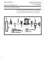
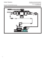
2-10 Flow Controller Installation Arrangement
Typical gas supply arrangements are shown in Figure 2-1. GF80s/GF81s
are often arranged inside a gas panel. Configure standard configurations
or "blanks" for a variety of pure gases and mixtures. As a result, MultiFlo
technology enables the user to reduce unique inventory requirements.
Figure 2-1 Typical Gas Supply Arrangement
Pagina se încarcă...
Pagina se încarcă...
Pagina se încarcă...
Pagina se încarcă...
Pagina se încarcă...
Pagina se încarcă...
Pagina se încarcă...
Pagina se încarcă...
Pagina se încarcă...
Pagina se încarcă...
Pagina se încarcă...
Pagina se încarcă...
Pagina se încarcă...
Pagina se încarcă...
Pagina se încarcă...
Pagina se încarcă...
Pagina se încarcă...
Pagina se încarcă...
Pagina se încarcă...
Pagina se încarcă...
Pagina se încarcă...
Pagina se încarcă...
Pagina se încarcă...
Pagina se încarcă...
Pagina se încarcă...
Pagina se încarcă...
Pagina se încarcă...
Pagina se încarcă...
Pagina se încarcă...
Pagina se încarcă...
Pagina se încarcă...
Pagina se încarcă...
Pagina se încarcă...
Pagina se încarcă...
Pagina se încarcă...
Pagina se încarcă...
Pagina se încarcă...
Pagina se încarcă...
Pagina se încarcă...
Pagina se încarcă...
Pagina se încarcă...
Pagina se încarcă...
Pagina se încarcă...
Pagina se încarcă...
Pagina se încarcă...
Pagina se încarcă...
Pagina se încarcă...
Pagina se încarcă...
Pagina se încarcă...
Pagina se încarcă...
Pagina se încarcă...
Pagina se încarcă...
Pagina se încarcă...
Pagina se încarcă...
Pagina se încarcă...
Pagina se încarcă...
-
 1
1
-
 2
2
-
 3
3
-
 4
4
-
 5
5
-
 6
6
-
 7
7
-
 8
8
-
 9
9
-
 10
10
-
 11
11
-
 12
12
-
 13
13
-
 14
14
-
 15
15
-
 16
16
-
 17
17
-
 18
18
-
 19
19
-
 20
20
-
 21
21
-
 22
22
-
 23
23
-
 24
24
-
 25
25
-
 26
26
-
 27
27
-
 28
28
-
 29
29
-
 30
30
-
 31
31
-
 32
32
-
 33
33
-
 34
34
-
 35
35
-
 36
36
-
 37
37
-
 38
38
-
 39
39
-
 40
40
-
 41
41
-
 42
42
-
 43
43
-
 44
44
-
 45
45
-
 46
46
-
 47
47
-
 48
48
-
 49
49
-
 50
50
-
 51
51
-
 52
52
-
 53
53
-
 54
54
-
 55
55
-
 56
56
-
 57
57
-
 58
58
-
 59
59
-
 60
60
-
 61
61
-
 62
62
-
 63
63
-
 64
64
-
 65
65
-
 66
66
-
 67
67
-
 68
68
-
 69
69
-
 70
70
-
 71
71
-
 72
72
-
 73
73
-
 74
74
-
 75
75
-
 76
76


în alte limbi
- eesti: Brooks GF80 Kasutusjuhend
Lucrări înrudite
-
 Brooks GF40 Instrucțiuni de utilizare
-
 Brooks GF100 / GF101 / GF120 / GF120XSL / GF120XSD / GF121 Instrucțiuni de utilizare
-
 Brooks VDM300 Instrucțiuni de utilizare
-
 Brooks 4850 Instrucțiuni de utilizare
-
 Brooks SLA585 Instrucțiuni de utilizare
-
 Brooks SLA5850 Instrucțiuni de utilizare
-
 Brooks 9861 Instrucțiuni de utilizare
-
 Brooks 5700 Instrucțiuni de utilizare
-
 Brooks SLAMf10 / SLAMf20 Ghid de instalare
-
 Brooks SLA5840, Revision B Instrucțiuni de utilizare


Alte documente
-
EHEIM compactON 16000 Manualul proprietarului
-
Grundfos Conex DIA-G Installation And Operating Instructions Manual
-
-
RIDGID micro CD-100 Manual de utilizare
-
Goodwe Smart meter Manual de utilizare
-
Facom DL.30T Manualul proprietarului
-
Güde GS, GSX Series Submersible Pump for Dirty Water Instrucțiuni de utilizare
-
-
-