Ubiquiti UVC-G3-DOME Ghid de inițiere rapidă
- Categorie
- Accesorii camere de securitate
- Tip
- Ghid de inițiere rapidă

DOME
Wide-Angle 1080p Dome
IP Camera with Infrared
Model: UVC-G3-DOME

Introduction
Thank you for purchasing the Ubiquiti Networks® UniFi®Video
Camera G3 Dome. This Quick Start Guide is designed to guide
you through installation and includes warranty terms.
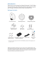
Package Contents
G3 Dome Camera Mounting Bracket Ceiling Backing Plate
Flat Head Screws
(M3x50, Qty. 4)
Keps Nuts
(M3, Qty. 4)
Screws
(M2.9x20, Qty. 4)
DOME
Wide-Angle 1080p Dome
IP Camera with Infrared
Model: UVC-G3-DOME
Screw Anchors
(M3x20, Qty. 4)
PoE Adapter* (24V, 0.5A)
with Mount Bracket
Power Cord* Quick Start
Guide
* Only the single-pack of the UVC-G3-DOME includes a PoE adapter and
a power cord.
TERMS OF USE: All Ethernet cabling runs must use CAT5 (or above). Shielded Ethernet cable
and earth grounding must be used for outdoor installations as conditions of product warranty.
TOUGHCable
™
is designed for outdoor installations. It is the customer’s responsibility to follow
local country regulations, including operation within legal frequency channels, output power,
and Dynamic Frequency Selection (DFS) requirements.

Installation Requirements
• Phillips screwdriver
• Drill and drill bit (6 mm for wall-mounting or 3 mm for
ceiling-mounting)
• Optional: Drywall saw or 18 mm keyhole saw
• Cat5/6 cable for indoor installations
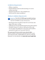
Outdoor Installation Requirements
Important: The UVC-G3-DOME may be installed outdoors
under an eave or other protected location. Do not install
the UVC-G3-DOME in an open environment.
• Mounting location should be at least 60 cm (2 ft) from the
edge of the eave or ceiling.
• Cable feed must be pointed downwards when wall-mounted.
• Shielded Category 5 (or above) cabling should be used
for all outdoor wired Ethernet connections and should be
grounded through the AC ground of the PoE.
We recommend that you protect your networks from
harmful outdoor environments and destructive ESD events
with industrial-grade, shielded Ethernet cable from Ubiquiti
Networks. For more details, visit www.ubnt.com/toughcable

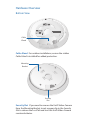
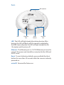
Hardware Overview
Bottom View
Cable
Gland
Cable Gland For outdoor installations, ensure the rubber
Cable Gland is installed for added protection.
Security
Slot
Mounting
Bracket
Security Slot If you need to remove the UniFi Video Camera
from the Mounting Bracket, insert a paper clip in the Security
Slot to release the Lock Tab and turn the UniFi Video Camera
counterclockwise.

Ports
Ethernet
Port
LED
Microphone
Reset
Button
microSD
Slot
LED The LED will light steady blue during bootup. After
bootup, the LED will flash until the camera is adopted by
the NVR. Upon adoption the LED will light steady blue for
10minutes and then turn off.
Ethernet The Ethernet port is a 10/100 Ethernet port used to
connect the power and should be connected to the LAN and
DHCPserver.
Reset To reset to factory defaults, press and hold the Reset
button for more than 10 seconds while the camera is already
powered on.
microSD Reserved for future use.

Hardware Installation
The UniFi Video Camera can be mounted on the wall or ceiling.
The Ethernet cable can be fed through a hole in the wall/ceiling
or can be run along the wall/ceiling.
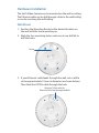
Wall Mount
1. Position the Mounting Bracket at the desired location on
the wall with the Arrow pointing up.
2. Mark the four mounting holes, and use a 6 mm drill bit to
drill the holes.
Arrow
3. If your Ethernet cable feeds through the wall, cut or drill a
circle approximately 18 mm in diameter (as shown below).
Then feed the CAT5/6 cable through the hole.
Optional 18 mm Hole for
Ethernet Cable Feed through the Wall

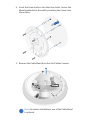
4. Insert the Screw Anchors into the 6 mm holes. Secure the
Mounting Bracket to the wall by inserting the Screws into
the anchors.
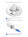
5. Remove the Cable Gland from the UniFi Video Camera.
Note: For indoor installations, use of the Cable Gland
is optional.

*640-00211-04*
640-00211-04
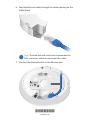
6. Feed the Ethernet cable through the cable opening on the
Cable Gland.
Note: The feed hole will stretch to accommodate the
RJ45 connector, and then seal around the cable.
7. Connect the Ethernet cable to the Ethernet port.

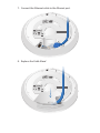
8. Replace the Cable Gland.
9. If the Ethernet cable is fed through the wall, skip to step10.
If the Ethernet cable runs along the mounting surface,
route the cable inside the cable channel.

10. Align the four tabs on the Mounting Bracket with the four
slots on the bottom of the camera.
Lock Tab
11. Rotate the camera clockwise until the tabs lock into place
and the Lock Tab engages.

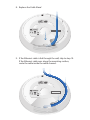
Ceiling Mount
1. Remove the ceiling tile.
2. Center the Mounting Bracket on the front side of the ceiling
tile and rotate the bracket to the desired direction of the
camera view. Mark the four mounting screw holes and an
18 mm hole for the Ethernet cable feed.
Direction of Camera View
18 mm Hole for Ethernet Cable Feed
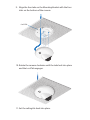
3. Use a 3 mm drill bit to drill the screw holes, and cut or drill
the hole for the Ethernet cable feed.

4. Insert the Flat Head Screws through the Mounting Bracket,
ceiling tile, and Ceiling Backing Plate. Fasten the screws
using the Keps Nuts. Then feed the Ethernet cable through
the tile and bracket.

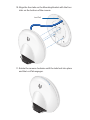
5. Remove the Cable Gland from the UniFi Video Camera.
Note: For indoor installations, use of the Cable Gland
is optional.
6. Feed the Ethernet cable through the cable opening on the
Cable Gland.
Note: The feed hole will stretch to accommodate the
RJ45 connector, and then seal around the cable.

7. Connect the Ethernet cable to the Ethernet port.
8. Replace the Cable Gland.

9. Align the four tabs on the Mounting Bracket with the four
slots on the bottom of the camera.
Lock Tab
10. Rotate the camera clockwise until the tabs lock into place
and the Lock Tab engages.
11. Set the ceiling tile back into place.

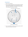
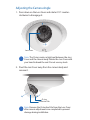
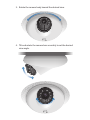
Adjusting the Camera Angle
1. Press down on the Lens Cover and rotate it 10° counter-
clockwise to disengage it.
Lens Cover
Note: The O-ring creates a tight seal between the Lens
Cover and the camera body. Rotate the Lens Cover with
your hand to break the seal. Do not use any tools.
2. Pivot the Lens Cover away from the camera body and
remove it.
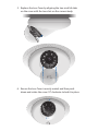
Protective Film
O-ring
Note: Remove the Protective Film from the Lens Cover
after camera adjustments are completed to prevent
damage during installation.

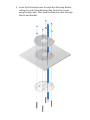
3. Rotate the camera body toward the desired view.
4. Tilt and rotate the camera lens assembly to set the desired
view angle.

5. Replace the Lens Cover by aligning the two small rib tabs
on the cover with the two slots on the camera body.
6. Ensure the Lens Cover is evenly seated, and then push
down and rotate the cover 10° clockwise to lock it in place.

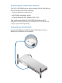
Powering the UniFi Video Camera
The UVC-G3-DOME features auto-sensing 802.3af PoE and can
be powered by any of the following:
• Ubiquiti Networks UniFi Switch
• 802.3af PoE compliant switch
• Ubiquiti Networks PoE Adapter (24V, 0.5A)
The single-pack of the UVC-G3-DOME includes one PoE
adapter. For multi-pack units, PoE adapters or a UniFi Switch
may be purchased separately.
Connecting to a PoE Switch
Connect the Ethernet cable from the UniFi Video Camera
directly to a PoE port on the switch.
1 3 5 7 9 11 13 15 17 19 21 22
2 4 6 8 10 12 14 16 18 20 22 24
SFP1
SFP2

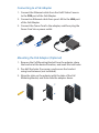
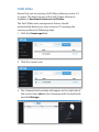
Connecting to a PoE Adapter
1. Connect the Ethernet cable from the UniFi Video Camera
to the POE port of the PoE Adapter.
2. Connect an Ethernet cable from your LAN to the LAN port
of the PoE Adapter.
3. Connect the Power Cord to the adapter, and then plug the
Power Cord into a power outlet.
Mounting the PoE Adapter (Optional)
1. Remove the PoE Mounting Bracket from the adapter, place
the bracket at the desired location, and mark the two holes.
2. Pre-drill the holes if necessary, and secure the bracket
using two fasteners (not included).
3. Align the slots on the adapter with the tabs of the PoE
Mounting Bracket, and then slide the adapterdown.
Pagina se încarcă...
Pagina se încarcă...
Pagina se încarcă...
Pagina se încarcă...
Pagina se încarcă...
Pagina se încarcă...
Pagina se încarcă...
Pagina se încarcă...
Pagina se încarcă...
Pagina se încarcă...
Pagina se încarcă...
Pagina se încarcă...
-
 1
1
-
 2
2
-
 3
3
-
 4
4
-
 5
5
-
 6
6
-
 7
7
-
 8
8
-
 9
9
-
 10
10
-
 11
11
-
 12
12
-
 13
13
-
 14
14
-
 15
15
-
 16
16
-
 17
17
-
 18
18
-
 19
19
-
 20
20
-
 21
21
-
 22
22
-
 23
23
-
 24
24
-
 25
25
-
 26
26
-
 27
27
-
 28
28
-
 29
29
-
 30
30
-
 31
31
-
 32
32


Ubiquiti UVC-G3-DOME Ghid de inițiere rapidă
- Categorie
- Accesorii camere de securitate
- Tip
- Ghid de inițiere rapidă
în alte limbi
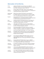
- English: Ubiquiti UVC-G3-DOME Quick start guide
- italiano: Ubiquiti UVC-G3-DOME Guida Rapida
Lucrări înrudite
-
Ubiquiti UVC-G3 Ghid de inițiere rapidă
-
Ubiquiti Networks UniFi Manualul utilizatorului
-
-
-
-
-
-
Ubiquiti UAP-PRO Ghid de inițiere rapidă
-
-