Rittal 3303.508 Assembly And Operating Instructions Manual
- Tip
- Assembly And Operating Instructions Manual

UL Type 12/3R/4
Cooling unit
Assembly and operating instructions
3303.5x8
3304.5x8
3305.5x8
3329.5x8

2 Rittal enclosure cooling unit
Warn- und Sicherheitshinweise / Safety instructions and warnings / Consignes de sécurité
Rittal Blue e enclosure cooling units
Hazards and their prevention according to IEC 60417/ISO 7000/ISO 7010
Warn- und Sicherhe itshinweise / Safety instructions and warnings / Consignes de sécurité
Warn- und Sicherhe itshinweise / Safety instructions and warnings / Consignes de sécurité
DE Die Anschlussvorschriften des zuständigen Stromversorgungsunternehmens sind zu beachten. Der Schutzleiter, der Haube und
Chassis verbindet, muss in jedem Fall an beiden Steckern angeschlossen werden. Ansonsten besteht bei einem fehlerhaftem oder de-
fekten Anschluss des Geräts Verletzungsgefahr durch Stromschlag.
EN The connection regulations of the appropriate power supply company are to be followed. The protective conductor between the
hood and the frame must always be attached to both plug connectors. Otherwise, there is risk of injury from electric shock if the connec-
tion to the unit is defective or connected incorrectly in any way.
FR Respecter les directives de raccordement du fournisseur d’électricité compétent. La tresse de mise à la masse qui relie le capot au
châssis doit dans tous les cas être raccordée aux deux fiches. Sinon il y a risque de blessure par électrocution en cas de raccordement
erroné ou défectueux de l’appareil.
NL Neem de aansluitvoorschriften van het desbetreffende energiebedrijf in acht. De beschermingsgeleiding, die de kap en het chassis
verbindt, dient in elk geval op beide connectoren te worden aangesloten. Anders bestaat bij een onjuiste of defecte aansluiting van het
apparaat een risico op letsel door een elektrische schok.
SE Anslutningsföreskrifterna från det ansvariga elförsörjningsföretaget måste följas. Skyddsledaren som förbinder huven och chassit
måste alltid vara ansluten till båda kontakterna. Annars finns risk för skador genom strömstötar vid felaktig eller defekt anslutning av ag-
gregatet.
IT Osservare le prescrizioni relative al collegamento dell’azienda fornitrice di elettricità competente. Il conduttore di protezione che col-
lega la copertura al telaio deve essere sempre collegato su entrambe le estremità. In caso di collegamento assente o errato del dispositivo
vi è il pericolo di lesioni dovute a scossa elettrica.
ES Deben tenerse en cuenta las normas de conexión de la compañía eléctrica competente. El conductor de protección, que conecta
la cubierta y el chasis, debe conectarse siempre a ambos conectores. En caso contrario, con una conexión errónea o defectuosa del
aparato, existe un peligro de lesión por descarga eléctrica.
FI Huomioi energiayhtiön liitäntäohjeet. Muussa tapauksessa laitteen virheellinen tai viallinen liitäntä saattaa aiheuttaa sähköiskusta joh-
tuvan loukkaantumisvaaran.
DK Følg altid tilslutningsvejledningen fra det ansvarlige elselskab. Beskyttelseslederen, som forbinder dækslet med chassiset, skal altid
være tilsluttet i begge stik. Hvis ikke dette er tilfældet, er der risiko for at få elektrisk stød som følge af forkert eller defekt tilslutning af
enheden.
IE Ní mór rialacháin nasctha na cuideachta cuí a sholáthraíonn an chumhacht a leanúint. Ní mór go mbeadh an seoltóir cosanta idir an
cochall agus an fráma nasctha leis an dá nascóir plocóide. Mura mbíonn, tá baol gortaithe ó thurraing leictreach má tá an nasc leis an
aonad lochtach nó má tá sé nasctha ar cearr ar bhealach ar bith.
PT Seguir as orientações da respectiva empresa de fornecimento de energia elétrica. O condutor de proteção que interliga a cobertura
com o chassi deve estar sempre conectado em ambas as extremidades. Caso contrário, haverá risco de choque elétrico se a conexão
do aparelho apresentar falha ou estiver incorreta.
HR Potrebno je pridržavati se pravila o priključivanju odgovarajućeg napona isporučitelja električne energije. Zaštitno uzemljenje između
poklopca i okvira mora uvijek s biti spojeno na priključne točke poklopca i okvira. Ukoliko zaštitno uzemljenje nije propisno spojeno ili je
oštećeno, postoji opasnost od ozljeda uzrokovanih strujnim udarom.
MT Għandhom jiġu osservati r-rekwiżiti tat-tqabbid tal-kumpanija tal-provvista tal-elettriku lokali. Il-konduttur protettiv li jqabbad il-hood
max-xażi għandu jkun imqabbad dejjem biż-żewġ plugs. Inkella jkun hemm ir-riskju ta’ xokk elettriku jekk ikun hemm konnessjoni mhux
tajba jew difettuża.
PL Przestrzegać przepisów odpowiedniego Zakładu Energetycznego. Przewód ochronny łączący pokrywę z obudową musi być zawsze
podłączony z obu stron. W przeciwnym razie, w przypadku błędnego lub wadliwego podłączenia urządzenia, istnieje niebezpieczeństwo
porażenia prądem elektrycznym.
CZ Dodržujte předpisy příslušného dodavatele elektrické energie pro připojení elektrického zařízení. V každém případě musí být připo-
jeny oba konektory ochranného vodiče, který spojuje přední plášť jednotky a její rám. Jinak hrozí při chybném nebo vadném připojení
přístroje nebezpečí úrazu elektrickým proudem.
BG Трябва да се спазват предписанията за свързване към захранването на компетентното електроснабдително дружество.
Заземяващият проводник, който свързва капака и рамата, във всички случаи трябва да се свърже към двата конектора. В про-
тивен случай съществува опасност от нараняване вследствие на токов удар в случай на неправилно или неизправно свързване
на уреда или неизправна електрическа мрежа.
GR Πρέπει να τηρούνται οι κανονισοί σύνδεσης της σχετικής εταιρείας παροχής ηλεκτρικού ρεύατος. Ο προστατευτικός αγωγός
εταξύ του καλύατος και του πλαισίου πρέπει να συνδέεται πάντα και στις δύο υποδοχές βύσατος. Σε αντίθετη περίπτωση, υπάρχει
κίνδυνος τραυατισού από ηλεκτροπληξία εάν η σύνδεση της ονάδας είναι ελαττωατική ή εσφαλένη.
RO Trebuie respectate cerinele de racordare ale companiei locale de alimentare cu energie. Conductorul de protecie dintre capac și
carcasa trebuie să fie conectat întotdeauna la ambele prize. În cazul în care conexiunea aparatului este incorectă sau defectuoasă, există
pericol de rănire prin electrocutare.

Rittal enclosure cooling unit 3
Warn- und Sicherheitshinweise / Safety instructions and warnings / Consignes de sécurité
Rittal Blue e enclosure cooling units
Hazards and their prevention according to IEC 60417/ISO 7000/ISO 7010
HU Az illetékes áramszolgáltató csatlakoztatási előírásait figyelembe kell venni. A burkolatot és a vázat összekötő védővezetéket minden
esetben mindkét csatlakozóhoz csatlakoztatni kell. Ellenkező esetben, a berendezés hibás vagy meghibásodott csatlakoztatása esetén
áramütés veszélye áll fenn.
LT Privalu laikytis atsakingos elektros tiekimo tinklų bendrovės parengtų instrukcijų. Apsauginis laidininkas, jungiantis gaubtą ir korpusą,
visada turi būti prijungtas prie abiejų jungčių. Įrenginio jungties pažeidimo ar defekto atveju kyla pavojus susižaloti gavus elektros smūgį.
EE Järgige vastutava elektrivarustuse ettevõtte vooluvõrku ühendamise eeskirju. Juhtkaitse, mis ühendab katet ja alusraami, peab igal
juhul olema mõlemast pistikust ühendatud. Vastasel korral tekib seadme puudulikul või defektsel ühendamisel vigastusoht elektrilöögi tõt-
tu.
LV Ievērojiet izmantotā elektropiegādes uzņēmuma pieslēguma noteikumus. Starp pārsegu un rāmi esošajam nulles vadam vienmēr ir
jābūt pievienotam abiem elektriskajiem spraudņiem. Pretējā gadījumā, ja iekārtas savienojumā ir radusies kļūme vai ja tā ir pieslēgta ne-
pareizi, pastāv risks ciest no elektriskās strāvas trieciena.
SI Upoštevati je treba predpise za priključevanje naprav pristojnega podjetja za distribucijo električne energije. Ozemljitveni priključek, ki
povezuje pokrov in ohišje, je treba v vsakem primeru namestiti na oba vtiča. V nasprotnem primeru pri napačni priključitvi ali okvarjenem
priključku obstaja nevarnost nastanka poškodb zaradi električnega udara.
SK Treba dbať na predpisy príslušného dodávateľa elektrickej energie týkajúce sa zapojenia. Ochranný vodič, ktorý spája kryt a spodnú
časť zariadenia, musí byť v každom prípade zapojený do oboch zásuviek. V opačnom prípade hrozí pri chybnom alebo nedostatočnom
zapojení zariadenia nebezpečenstvo úrazu elektrickým prúdom.
RU Необходимо соблюдать указания по подключению компетентного энергопредприятия. Провод заземления, соединяющий
кожух и основание, должен быть обязательно подключен с двух сторон. В противном случае при отсутствующем или повре-
жденном подключении имеется опасность поражения током.
DE Bitte beachten Sie die maximal zulässigen Hebegewichte für Personen. Ggf. ist eine Hebevorrichtung zu verwenden.
EN Please observe the maximum permissible weight to be lifted by one person. Use suitable lifting devices, if needed.
FR Veuillez tenir compte du poids de levage maximal autorisé pour les personnes et le cas échéant utilisez un appareil de levage.
NL Neem het maximaal toegestane tilgewicht voor personen in acht. Gebruik eventueel een hefwerktuig.
SE Observera de maximalt tillåtna lyftvikterna för personer. Vid behov ska en lyftanordning användas.
IT Prestare attenzione ai carichi massimi consentiti per le persone. Se necessario, utilizzare un dispositivo di sollevamento.
ES Rogamos tenga en cuenta el peso máximo permitido que puede levantar una persona. En caso necesario deberá utilizarse un dis-
positivo de elevación.
FI Huomioi sallittu enimmäisnostopaino. Käytä tarvittaessa nostolaitetta.
DK Overhold den maksimalt tilladte løftevægt for personer. Brug en løfteanordning, hvis vægten overskrider den tilladte løftevægt.
IE Cloígh leis an uasmheáchan is ceadmhach do dhuine amháin a chrochadh. Úsáid gairis ardaithe atá oiriúnach, más gá.
PT Por favor, considerar o peso máximo permitido a ser levantado por uma pessoa. Caso necessário, utilizar equipamento adequado.
HR Obratite pažnju na najveću dopuštenu masu koju smije podizati jedna osoba. Ako je potrebno, preporuča se upotreba opreme za
podizanje i premještanje.
MT Jekk jogħġbok innota l-piżijiet ta’ rfigħ massimi permessibbli għan-nies. Jekk ikun hemm bżonn, jeħtieġ li jintuża apparat tal-irfigħ.
PL Prosimy o nieprzekraczanie maksymalnych dopuszczalnych ciężarów podnoszonych przez ludzi. W razie potrzeby należy zastoso-
wać urządzenie podnośnikowe.
CZ Dodržujte maximální přípustné hmotnosti zvedaných břemen stanovené pro osoby. Případně použijte zvedací zařízení.
BG Спазвайте максимално допустимата товароносимост на човек при транспортиране на охладителя. Ако се налага, използ-
вайте подемно устройство.
GR Παρακαλούε τηρείτε το έγιστο επιτρεπόενο βάρος που πορεί να αρθεί από ένα άτοο. Χρησιοποιήστε κατάλληλες συσκευές
ανύψωσης, εάν είναι απαραίτητο.
RO Respectai greutăile de ridicare maxim admise pentru o persoana. Dacă este necesar, utilizai dispozitive de ridicare.
HU Vegye figyelembe az egy személy számára maximálisan megengedett emelhető tömegeket. Szükség esetén emelőberendezést kell
használni.
LT Žmonės neturėtų kelti pernelyg sunkaus svorio. Prireikus reikia naudoti kėlimo įrangą.
EE Arvestage inimestele maksimaalselt lubatud tõstekaaludega. Vajaduse korral kasutage tõsteseadeldist.
LV Lūdzu, ievērojiet ierobežojumus attiecībā uz maksimālo svaru, ko ļauts celt vienai personai. Izmantojiet atbilstošas celšanas ierīces,
kad tas ir nepieciešams.
SI Upoštevajte največjo dovoljeno težo, ki jo oseba lahko varno dvigne. Po potrebi uporabite dvižno napravo.
SK Dodržiavajte maximálne limity pre osoby na zdvíhanie bremien. V prípade prekročenia tohto limitu použite zdvíhacie zariadenie.
RU При транспортировке вручную обращайте внимание на максимально допустимый вес. При необходимости используйте
подъемное устройство.

4 Rittal enclosure cooling unit
Warn- und Sicherheitshinweise / Safety instructions and warnings / Consignes de sécurité
Rittal Blue e enclosure cooling units
Hazards and their prevention according to IEC 60417/ISO 7000/ISO 7010
DE Das Kühlgerät ist nur standsicher, solange Haube und Chassis miteinander verbunden sind. Sichern Sie daher insbesondere das
Chassis gegen Umfallen, bevor Sie die Haube abnehmen.
EN The cooling unit only stands safely while the hood and chassis are joined to each other. Ensure that the frame, in particular, is secured
against tipping before removing the hood.
FR Le climatiseur est stable uniquement si le capot et le châssis sont reliés entre eux. S’assurer pour cela que le châssis ne puisse pas
tomber avant d’ôter le capot.
NL Het koelaggregaat is alleen stabiel zo lang kap en chassis met elkaar zijn verbonden. Zorg er daarom voor dat als u de kap verwijdert,
het chassis niet kan omvallen.
SE Kylaggregatet står endast stabilt så länge huven och chassit är förbundna med varandra. Säkra därför framför allt chassit så att det
inte välter, innan du tar av huven.
IT Il condizionatore è stabile solo se la copertura e il telaio sono collegati tra loro. Mettere pertanto il telaio in sicurezza da eventuali cadute
prima di rimuovere la copertura.
ES El refrigerador sólo se encuentra suficientemente estable, cuando la cubierta y el chasis se encuentran conectados el uno con el
otro. Por este motivo es importante proteger especialmente el chasis de una caída, antes de retirar la cubierta.
FI Jäähdytin on vakaa vain, kun kehikko ja runko on kiinnitetty toisiinsa. Tue erityisesti runko kaatumisen varalta ennen suojuksen irrot-
tamista.
DK Køleenheden står kun sikkert fast, hvis dækslet og chassiset er forbundet med hinanden. Sørg derfor for at sikre chassiset, så det
ikke vælter, før dækslet tages af.
IE Ní bhíonn an t-aonad fuaraithe ina sheasamh go sábháilte ach amháin nuair atá an cochall agus an fonnadh nasctha le chéile. Cinntigh
go ndaingnítear an fráma, go háirithe, sula mbaintear an cochall de, sa chaoi nach n-iompóidh sé.
PT O condicionador de ar estará fixo apenas quando a cobertura estiver conectada ao chassi. Antes de remover a cobertura, certificar-
se de que o chassi esteja seguro e não possa tombar.
HR Rashladna jedinica stoji sigurno samo ukoliko su poklopac i kućište međusobno ispravno spojeni. Obratite posebnu pažnju da je
okvir osiguran od prevrtanja prije nego uklanjate poklopac rashladne jedinice.
MT L-unità ta’ tkessiħ hija stabbli biss meta x-xażi u l-hood it-twila jkunu mqabbdin ma’xulxin. Oqgħod attent/a b’mod partikolari li x-
xażi ma jegħlibx qabel tneħħi l-kappa.
PL Urządzenie jest stabilne tylko wówczas, gdy pokrywa i obudowa są ze sobą połączone. Dlatego przed zdjęciem pokrywy należy
zabezpieczyć obudowę przed przewróceniem się.
CZ Chladicí jednotka je stabilní jen v případě namontovaného pláště na chladicí jednotce. Před sejmutím pláště proto zajistěte samotný
rám jednotky proti převrhnutí.
BG Климатикът е стабилен само когато капакът и рамата са свързани помежду си. Затова укрепете най-вече рамата срещу
падане, преди да свалите капака.
GR Η ονάδα ψύξης στέκεται ε ασφάλεια όνο όταν το κάλυα και το πλαίσιο έχουν συνδεθεί εταξύ τους. Βεβαιωθείτε ότι ειδικά
το πλαίσιο είναι ασφαλισένο έναντι ανατροπής πριν αφαιρέσετε το κάλυα.
RO Aparatul de răcire este stabil numai dacă sunt interconectate capacul și carcasa. În acest scop, asigurai carcasa împotriva căderii,
înainte de a scoate capacul.
HU A hűtőberendezés csak akkor áll biztonságosan, ha a burkolat és a váz egymással össze van kötve. Ezért a vázat biztosítsa eldőlés
ellen, mielőtt a burkolatot leveszi.
LT Šaldymo įrenginys stabilus tol, kol gaubtas sujungtas su korpusu. Todėl prieš nuimdami gaubtą, įsitinkinkite, kad korpusas yra sta-
bilus ir nenukristų.
EE Jahutusseade on kindlalt püsti vaid siis, kui kate ja alusraam on omavahel ühendatud. Kindlustage ümberkukkumise vastu alusraam
enne katte mahavõtmist.
LV Dzesēšanas bloka droša novietošana tiek paveikta pārsegu pienācīgi savienojot ar konstrukciju. Pārliecinieties par to, lai rāmis būtu
pasargāts pret sasvēršanos, pirms pārsega noņemšanas.
SI Hladilna naprava je stabilna, dokler sta pokrov in ohišje klime povezana. Preden snamete pokrov, je zato potrebno ohišje še posebej
zavarovati, da se ne prevrne.
SK Klimatizačné zariadenie je stabilné len vtedy, ak sú kryt a spodná časť spojené. Najmä spodnú časť preto zaistite pred prevrátením
ešte skôr, ako odstránite kryt.
RU Холодильный агрегат устойчив в вертикальном положении, когда кожух и основание соединены между собой. Поэтому
перед удалением кожуха защитите основание агрегата от опрокидывания.

Rittal enclosure cooling unit 5
Warn- und Sicherheitshinweise / Safety instructions and warnings / Consignes de sécurité
Rittal Blue e enclosure cooling units
Hazards and their prevention according to IEC 60417/ISO 7000/ISO 7010
DE Vor dem Abnehmen der Haube muss das Gerät mind. 10 Min. abkühlen, um Verbrennungen an heißen Oberflächen zu vermeiden.
EN Before removing the hood, allow the unit to cool for at least 10 minutes to eliminate the risk of burns from hot surfaces.
FR Avant d’ôter le capot, l’appareil doit refroidir pendant au moins 10 minutes pour éviter les brûlures sur les surfaces brûlantes.
NL Voor het afnemen van de kap dient het apparaat minstens tien minuten af te koelen, zodat u zich niet brandt aan hete oppervlakken.
SE Innan huven tas av måste aggregatet svalna i minst 10 minuter för att undvika att personer bränner sig på heta ytor.
IT Far raffreddare il dispositivo per almeno 10minuti prima di rimuovere la copertura per evitare eventuali ustioni al contatto con le su-
perfici bollenti.
ES El aparato debe haberse enfriado durante un mínimo de 10 minutos antes de proceder a retirar la cubierta, con el fin de evitar que-
maduras.
FI Ennen kehikon irrottamista laitteen on annettava jäähtyä vähintään 10 minuuttia, jotta vältetään kuumien pintojen aiheuttamat palo-
vammat.
DK Lad enheden køle af i mindst ti minutter, før dækslet tages af, for at undgå risiko for at brænde sig på varme overflader.
IE Sula mbaintear an cochall de, lig don aonad fuarú ar feadh deich nóiméad ar a laghad chun an baol dó ó dhromchlaí teo a sheachaint.
PT Antes de remover a cobertura, deixar o aparelho arrefecer durante, no mínimo, 10minutos para evitar risco de queimadura nas
superfícies quentes.
HR Prije uklanjanja poklopca pričekajte barem 10 minuta da se uređaj ohladi, kako bi se uklonila opasnost od opekotina uzrokovanih
vrućim površinama.
MT Qabel tneħħi l-għatu, l-apparat għandu jitħalla jibred għal mill-inqas 10 min biex tevita ħruq minħabba uċuh jaħarqu.
PL Przed zdjęciem pokrywy urządzenie musi się chłodzić przez minimum 10 minut, aby nie doszło do poparzenia przez gorące po-
wierzchnie.
CZ Před sejmutím pláště jednotky je nutno nechat chladicí jednotku minimálně 10 minut vychladnout, aby nedošlo k popálení o horké
povrchy.
BG Преди да бъде свален капакът, уредът трябва да се остави да изстине най-малко 10 минути, за да се избегнат изгаряния
от горещите повърхности.
GR Πριν αφαιρέσετε το κάλυα, αφήστε τη ονάδα να ψυχθεί για τουλάχιστον 10 λεπτά για να εξαλειφθεί ο κίνδυνος εγκαυάτων
από καυτές επιφάνειες.
RO Înainte de scoaterea capacului, aparatul trebuie lăsat să se răcească cel puin 10 min., pentru a evita arsurile cauzate de contactul
cu suprafeele fierbini.
HU A burkolat levétele előtt a berendezést legalább 10 percig hagyja lehűlni a forró felületek miatti égési sérülések elkerülése érdekében.
LT Prieš nuimdami gaubtą, turite palaukti bent 10 minučių, kol įrenginys atvės, kad nenusidegintumėte prisilietę prie karštų paviršių.
EE Enne katte mahavõtmist peab seade vähemalt 10 minutit jahtuma, et vältida põletusi kuumade pindade tõttu.
LV Pirms pārsega atvēršanas, ļaujiet iekārtai atdzist vismaz 10 minūtes, lai izvairītos no apdedzināšanās riska, ko rada uzkarsušās virs-
mas.
SI Preden snamete pokrov, naj se naprava najmanj 10 minut ohlaja, da se izognete nevarnosti opeklin na vročih površinah.
SK Pred odstránením krytu musí zariadenie minimálne 10 minút chladnúť, inak môže dôjsť k popáleniu na horúcich povrchoch.
RU Перед снятием кожуха дать агрегату остыть в течение ок. 10 мин., во избежание ожога о горячие поверхности.
DE Verwenden Sie niemals brennbare Flüssigkeiten zur Reinigung des Geräts.
EN Never use flammable liquids for cleaning.
FR Ne jamais utiliser de liquides inflammables pour le nettoyage.
NL Gebruik geen brandbare vloeistoffen voor het reinigen.
SE Använd inga brännbara vätskor för rengöring.
IT Non utilizzare liquidi infiammabili per la pulizia.
ES No utilice líquidos inflamables para realizar la limpieza.
FI Älä käytä puhdistukseen palavia nesteitä.
DK Brug aldrig brændbare væsker til rengøring.
IE Ná húsáid leachtanna inlasta riamh i gcomhair glanta.
PT Nunca utilizar líquidos inflamáveis para efetuar a limpeza.
HR Nikada ne koristite zapaljive tekućine za čišćenje.

6 Rittal enclosure cooling unit
Warn- und Sicherheitshinweise / Safety instructions and warnings / Consignes de sécurité
Rittal Blue e enclosure cooling units
Hazards and their prevention according to IEC 60417/ISO 7000/ISO 7010
MT Tużax likwidi li jieħdu n-nar għat-tindif.
PL Do czyszczenia urządzenia nie stosować łatwopalnych cieczy.
CZ Nepoužívejte k čištění žádné hořlavé kapaliny.
BG Не използвайте запалими течности за почистване.
GR Μη χρησιοποιείτε ποτέ εύφλεκτα υγρά για τον καθαρισό.
RO Nu utilizai lichide inflamabile pentru curăare.
HU Tisztításhoz ne használjon gyúlékony folyadékot.
LT Valydami nenaudokite degių skysčių.
EE Ärge kasutage puhastamiseks põlevaid vedelikke.
LV Nekad neizmantojiet uzliesmojošus tīrīšanas līdzekļus.
SI Za čiščenje ne uporabljajte vnetljivih tekočin.
SK Na čistenie nepoužívajte horľavé kvapaliny.
RU Никогда не используйте горючие жидкости для чистки агрегата.
DE Das Kühlgerät ist ausschließlich zum Kühlen von geschlossenen Schaltschränken sowie zur professionellen Nutzung gemäß DIN EN
61000-3-2 vorgesehen. Eine andere Verwendung ist nicht bestimmungsgemäß. Das Gerät darf nicht an Orten installiert und betrieben
werden, die der allgemeinen Öffentlichkeit (siehe DIN EN 60335-2-40, Absatz 3.119) zugänglich sind. Das Gerät ist nur für den stationären
Betrieb ausgelegt.
EN The cooling unit is intended exclusively for cooling closed control cabinets as well as for professional use in accordance with DIN
EN 61000-3-2. Any other use is not permitted. The unit must not be installed and operated in locations which are accessible to the general
public (see DIN EN 60335-2-40, paragraph 3.119). The unit is designed solely for stationary use.
FR Le climatiseur est prévu uniquement pour rafraîchir les armoires électriques étanches dans un cadre professionnel conformément a
la norme EN 61000-3-2. Toute autre utilisation est non conforme. Le climatiseur ne doit pas être installé et exploité dans des lieux acces-
sibles au public (voir norme EN 60335-2-40, paragraphe 3.119). Le climatiseur est uniquement destiné à l'exploitation statique.
NL Het koelaggregaat is uitsluitend bestemd voor het koelen van gesloten schakelkasten en voor professioneel gebruik volgens DIN EN
61000-3-2. Elke andere toepassing wordt gezien als niet-voorgeschreven gebruik. Het apparaat mag niet worden geïnstalleerd op plaat-
sen die openbaar (zie DIN EN 60335-2-40, paragraaf 3.119) toegankelijk zijn. Het apparaat is alleen ontworpen voor stationair gebruik.
SE Kylaggregatet är endast avsedd för kylning av slutna golvskåp i enlighet med DIN EN 61000-3-2. Annan användning är inte tillåten.
Aggregatet får inte installeras och köras på platser som är tillgängliga för allmänheten (se DIN EN 60335-2-40, stycke 3.119). Aggregatet
är konstruerat uteslutande för stationär drift.
IT Il condizionatore è destinato esclusivamente al raffreddamento degli armadi di comando chiusi e per uso professionale secondo EN
61000-3-2. Ogni altro impiego è da intendersi non conforme alla sua destinazione d’uso. L’apparecchio non deve essere installato e uti-
lizzato in aree accessibili al pubblico (vedere la norma DIN EN 60335-2-40, paragrafo 3.119). L’apparecchio può essere utilizzato solo da
fermo.
ES El refrigerador se ha diseñado exclusivamente para la refrigeración de armarios de distribución estancos, para su uso según lo de-
tallado en la normativa DIN EN 61000-3-2. Cualquier otro uso no está permitido. El equipo no debe ser instalado ni puesto en funciona-
miento en entornos accesibles al público en general (ver DIN EN 60335-2-40, párrafo 3.119). El equipo está diseñado para un funciona-
miento estacionario.
FI Jäähdytysyksikkö on tarkoitettu yksinomaan suljettujen koteloiden jäähdytykseen sekä ammattikäyttöön DIN EN 61000-3-2 mukai-
sesti. Mikään muu käyttö ei ole sallittua. Laitetta ei saa asentaa ja käyttää yleisessä käytössä olevissa paikoissa (katso DIN EN 60335-2-
40, kohta 3.119). Laite on suunniteltu ainoastaan kiinteään käyttöön.
DK Køleenheden er kun beregnet til køling af lukkede indkapslinger og kun til professionelt brug i henhold til DIN EN 61000-3-2. Enhver
anden brug er ikke tilladt. Enheden må ikke installeres eller opereres på lokaliteter med offentlig adgang (Se DIN EN 60335-2-40, paragraf
3.119) Enheden er udelukkende designet til stationært brug.
IE Nil an t-aonad fuaraithe ceaptha ach amháin d'fhuarú na gcaibinéad rialaithe dúnta agus d'úsáid ghairmiúil eile i gcomhréir le DIN EN
61000-3-2. Ní cheadaítear d’aon úsáid eile. Ná suiteáiltear agus ná oibrítear an t-aonad i suíomhanna arb inrochtana don phobal i
gcoitinne iad (féach DIN EN 60335-2-40, mír 3.119). Is le húsáid dho-aistrithe amháin a dearadh an t-aonad.
PT A unidade de refrigeração destina-se exclusivamente à refrigerar gabinetes de controle fechados, bem como para uso profissional
de acordo com a DIN EN 61000-3-2. Qualquer outro uso não é apropriado e não é permitido. O aparelho não deve ser instalado e ope-
rado em locais acessíveis ao público em geral (consulte a norma DIN EN 60335-2-40, seção 3.119). O aparelho foi projetado apenas
para o uso em instalação fixa.
HR Klima uređaj namijenjen je isključivo hlađenu nanizanih ormara te profesionalnoj uporabi sukladno DIN EN 61000-3-2. Drugačija upo-
raba nije dozvoljena. Uređaj se ne smije instalirati i raditi na mjestima gdje je dostupan javnosti (DIN EN 60335-2-40, paragraph 3.119).
Uređaj je namijenjen isključivo za unutarnju upotrebu.
MT It-tagħmir refriġeranti għandu jintuża esklussivament biex ikessaħ l-armarji magħluqin kif ukoll għall-użu professjonali skont DIN EN
61000-3-2. Użu ieħor ta’ dan huwa ħażin. L-apparat ma għandux jiġi installat u ma għandux jitħaddem f’postijiet li huma aċċessibbli għall-
pubbliku (ara DINEN60335-2-40, Paragrafu3.119). L-apparat huwa ddisinjat biss għal tħaddim stazzjonarju.
PL To urządzenie chłodnicze jest przewidziane wyłącznie do chłodzenia zamkniętych szaf sterowniczych oraz do użytku profesjonalne-
go zgodnie z normą DIN EN 61000-3-2. Każde inne zastosowanie jest niezgodne z przeznaczeniem. Urządzenie nie może być instalo-

Rittal enclosure cooling unit 7
Warn- und Sicherheitshinweise / Safety instructions and warnings / Consignes de sécurité
Rittal Blue e enclosure cooling units
Hazards and their prevention according to IEC 60417/ISO 7000/ISO 7010
wane i użytkowane w miejscach ogólnodostępnych (patrz EN 60335-2-40, punkt 3.119). Urządzenie jest przystosowane wyłącznie do
użytkowania stacjonarnego.
CZ Chladicí jednotka je určena výhradně k chlazení uzavřených rozváděčových skříní a k profesionálnímu použití v souladu s ČSN EN
61000-3-2. Jiné použití není použití v souladu s určením. Zařízení se nesmí instalovat a provozovat na místech, která jsou veřejně přístup-
ná (viz DIN EN 60335-2-40, oddíl 3.119). Zařízení je navrženo jen pro stacionární provoz.
BG Охладителното устройство е предназначено само за охлаждане на кутии и шкафове както и за професионална употреба
съгласно DIN EN 61000-3-2. Не се разрешава всякаква друга употреба. Уредът не трябва да се монтира и работи в местата,
които са достъпни за широката общественост (виж DIN EN 60335-2-40, параграф 3.119). Уредът е предназначен единствено за
стационарна употреба.
GR Η ονάδα ψύξης προορίζεται αποκλειστικά για ψύξη κλειστούς πίνακες ελέγχου καθώς και για επαγγελατική χρήση σύφωνα ε
το DIN EN 61000-3-2. Οποιαδήποτε άλλη χρήση δεν επιτρέπεται. εν επιτρέπεται η εγκατάσταση και η λειτουργία της συσκευής σε
σηεία, τα οποία είναι προσβάσιες στο ευρύ κοινό (δείτε DIN EN 60335-2-40, σηείο 3.119). Η συσκευή έχει σχεδιαστεί αποκλειστικά
για στατική χρήση.
RO Climatizorul este conceput doar pentru racirea dulapurilor inchise precum si pentru o utilizare industriala conform normelor DIN EN
61000-3-2. Orice alta utilizare nu este permisa. Unitatea nu trebuie instalata si folosita in locatii la care are acces publicul larg. (vezi DIN
EN 60335-2-40, paragraf 3.119). Unitatea este proiectata doar pentru utilizare stationara.
HU A hűtőberendezés kizárólag zárt kapcsoló- és vezérlőszekrények hűtésére, valamint a DIN EN 61000-3-2 szabvánnyal összhangban
történő professzionális alkalmazásra használható. Minden más alkalmazás tilos. A berendezést tilos olyan helyre telepíteni és üzemeltetni,
amely szabadon hozzáférhető laikusok számára (lásd DIN EN 60335-2-40, 3.119 bekezdés). A berendezést kizárólag fixen telepítve és
álló helyzetben szabad telepíteni és üzemeltetni.
LT Vėsinimo agregatas skirtas tik uždaro tipo skydų vėsinimui, taip pat profesionaliam naudojimui pagal DIN EN 61000-3-2. Bet koks
kitas naudojimas yra draudžiamas. Agregatas negali būti sumontuojamas ir eksplotuojamas viešai prieinamose vietose (pagal DIN EN
60335-2-40, punktas 3.119). Prietaisas skirtas tik stacionariam naudojimui.
EE Jahutusseadmed on ettenähtud ainult kinniste kilpide jahutamiseks ja professionaalseks kasutamiseks vastavalt standardile DIN EN
61000-3-2. Muu laadne kasutus ei ole lubatud. Seadmete kasutus üldkasutatavates ruumides ei ole lubatud (vaata DIN EN 60335-2.40,
§ 3.119). Seade on ettenähtud ainult statsionaarseks paigalduseks.
LV Dzesēšanas bloks paredzēts tikai sadaļņu ar slēgto kontroli dzesēšanai, kā arī profesionālai lietošanai saskaņā ar DIN EN 61000-3-
2. Jebkura cita izmantošana nav atļauta. Iekārtu nedrīkst uzstādīt un izmantot publiski pieejamās vietās (skatīt standarta DIN EN60335-
2-40, paragrāfu 3.119). Iekārta ir izstrādāta tikai stacionārai lietošanai.
SI Hladilna naprava je namenjena samo za hlajenje vrstno povezanih ohišij, kot tudi za profesionalno uporabo skladno z DIN EN 61000-
3-2. Vsaka druga uporaba ni dovoljena. Naprava ne sme biti nameščena in delovati na lokaciji ki je dostopna širši javnosti (glej DIN EN
60335-2-40, odstavek 3.119). Naprava je namenjena izključno za stacionarno uporabo.
SK Chladiaca jednotka je určená pre chladenie uzavretých rozvádzačových skríň ako aj iných zariadení, ktoré sú v súlade s normou DIN
EN 61000-3-2. Iné použitie nie je prípustné. Zariadenie nesmie byť inštalované a používané vo verejne dostupných priestoroch (viď DIN
EN 60335-2-40, odstavec 3.119). Zariadenie je určené na stacionárnu prevádzku.
RU Агрегат предназначен исключительно для охлаждения закрытых распределительных шкафов, а также для профессио-
нального использования согл. DIN EN 61000-3-2. Использование в других целях не соответствует его прямому назначению.
Агрегат нельзя устанавливать и эксплуатировать в местах, доступных для постронних лиц (см. DIN EN 60335-2-40, абзац 3.119).
Агрегат предназначен для только для стационарного применения.

Contents
EN
8 Rittal enclosure cooling unit
Contents
1 Notes on documentation .................. 9
1.1 CE labelling.................................................. 9
1.2 Storing the documents................................. 9
1.3 Symbols used.............................................. 9
2 Safety notes ..................................... 9
3 Device description ............................ 9
3.1 Functional description ................................ 10
3.1.1 How it works ....................................................... 10
3.1.2 Control ................................................................ 10
3.1.3 Bus mode ........................................................... 10
3.1.4 Safety equipment ................................................ 10
3.1.5 Condensation ..................................................... 11
3.1.6 Filter mats ........................................................... 11
3.1.7 Door limit switch ................................................. 11
3.1.8 Additional interface X3 ........................................ 11
3.2 Proper use, foreseeable misuse ................. 11
3.3 Scope of supply......................................... 12
4 Assembly and connection .............. 12
4.1 Choosing the installation site...................... 12
4.2 Assembly instructions ................................ 12
4.2.1 General ............................................................... 12
4.2.2 Layout of the electronic components in the
enclosure ............................................................ 12
4.3 Fitting the cooling unit ................................ 13
4.3.1 Cutting out on the enclosure ............................... 13
4.3.2 External mounting of the cooling unit ................... 13
4.4 Notes on electrical installation .................... 13
4.4.1 Connection data ................................................. 14
4.4.2 Electrical Box connection .................................... 14
4.4.3 Overvoltage protection and supply line load ........ 14
4.4.4 Door limit switch ................................................. 14
4.4.5 Notes on the flicker standard .............................. 15
4.4.6 Potential equalization .......................................... 15
4.5 Carrying out the electrical installation.......... 15
4.5.1 Bus connection (only in conjunction with several
units with an e-Comfort controller) ....................... 15
4.5.2 Connection X3 for serial interface ........................ 15
4.5.3 Installing the power supply .................................. 16
5 Commissioning ............................... 17
6 Operation ....................................... 17
6.1 Control using the e-Comfort controller ....... 17
6.1.1 Properties ........................................................... 17
6.1.2 Eco mode ........................................................... 18
6.1.3 Launching test mode .......................................... 18
6.1.4 General information about programming ............. 18
6.1.5 Editable parameters ............................................ 20
6.1.6 Programming overview ....................................... 21
6.1.7 Defining system messages for evaluation ............ 22
6.1.8 Setting the master/slave identifier ........................ 22
6.1.9 Evaluating system messages .............................. 23
6.1.10 Reset the e-Comfort controller ............................ 25
7 Inspection and maintenance .......... 25
7.1 General ...................................................... 25
7.2 Cleaning the filter mat................................. 25
7.3 Compressed air cleaning............................ 26
8 Storage and disposal ..................... 28
9 Technical specifications ................. 29
10 Appendix: Cut-out and hole sizes .. 34

Rittal enclosure cooling unit 9
1 Notes on documentation
EN
1 Notes on documentation
These assembly instructions are aimed at tradespersons
who are familiar with assembly and installation of the
cooling unit, and at trained specialists who are familiar
with operation of the cooling unit.
1.1 CE labelling
Rittal GmbH & Co. KG confirms the conformity of the
cooling unit with the European Union's Machinery Direc-
tive 2006/42/EC and EMC Directive 2014/30/EC. A cor-
responding declaration of conformity has been issued.
This can be found at the end of this document, or on the
Rittal homepage.
1.2 Storing the documents
The assembly and operating instructions as well as all
other applicable documents are an integral part of the
product. They must be issued to everyone who works
with the unit and must always be available and on hand
for operating and maintenance personnel.
1.3 Symbols used
Please observe the following safety instructions and oth-
er notes in this guide:
Symbol for an instructed action:
The bullet point indicates that you should perform an
action.
Safety and other instructions:
2 Safety notes
Please observe the following general safety instructions
when assembling and operating the unit:
– Assembly, installation and servicing may only be per-
formed by properly trained specialists.
– Screw the enclosure to the floor to prevent it from tip-
ping over when the cooling unit is installed.
– Do not obstruct the air inlet and air outlet of the cooling
unit inside and outside the enclosure (see also sec-
tion4.2.2 "Layout of the electronic components in the
enclosure").
– To ensure problem-free opening and closing of the en-
closure door, use a ride-up door roller. This raises the
door slightly and balances out the weight of the cool-
ing unit, to prevent buckling of the door and associat-
ed seal problems.
– The heat loss of the components installed in the enclo-
sure must not exceed the specific useful cooling out-
put of the cooling unit.
– Cooling units must be transported in an upright posi-
tion and protected from tipping over.
– Shipping braces must be used when transporting a
unit that has already been mounted (on the enclosure).
A wooden structure made from square timbers or
boards to support the cooling unit at the bottom is
suitable for this purpose. The pallet should be big
enough to prevent the enclosure and cooling unit
overturning. If the cooling unit is mounted on a door,
ensure the door is kept closed during transport.
– Use only original spare parts and accessories.
– Do not make any changes to the cooling unit other
than those described in these instructions or associat-
ed instructions.
– Risk of burn injuries! On cooling units with automatic
condensate evaporation, the surface of the thermal el-
ement will get very hot during operation, and will re-
main so for some time afterwards.
– The mains connector of the cooling unit must only be
connected and disconnected with the system de-en-
ergized. Connect the protective device specified on
the rating plate.
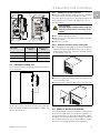
3 Device description
Depending on the model chosen, your cooling unit may
vary in appearance from the illustrations contained in
these instructions. However, the functions are identical
in principle.
Danger!
Immediate danger to life and limb!
Caution!
Potential threat to the product and its
environment.
Note:
Useful information and special features.

3 Device description
EN
10 Rittal enclosure cooling unit
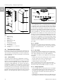
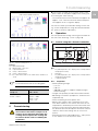
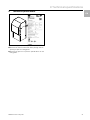
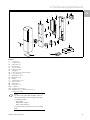
Fig. 1: Device description
Key
1 Blind rivet nut
2 Evaporator fan
3Display
4 Electrical box
5 Evaporator air outlet
6 Metal air filter
7 Air inlet external circuit
8 Condensate discharge
9 Metal air filter
10 Louvred grille for condenser air
11 Housing
3.1 Functional description
Enclosure cooling units are designed to dissipate heat
from enclosures by cooling the air inside the enclosure
and so protect the temperature-sensitive components.
They are built into the side or rear panel or into the door
of the enclosure.
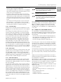
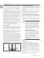
3.1.1 How it works
The cooling unit (compression refrigeration system) is
comprised of four main components (fig. 2): the evapo-
rator (1), the coolant compressor (2), the condenser (3),
and the control or expansion valve (4), which are con-
nected by suitable pipework. This circuit is filled with a
readily boiling substance, the refrigerant. Coolant R134a
(CH
2
FCF
3
) is chlorine-free. Its ozone destruction poten-
tial is 0, making it very ecofriendly. A filter dryer (5) which
is integrated into the hermetically sealed cooling circuit
provides effective protection against moisture, acid, dirt
particles, and foreign bodies within the cooling circuit.
Fig. 2: Cooling circuit
In the evaporator coil (1), the liquid coolant is converted
to a gaseous state. The energy needed for this purpose
is taken from the enclosure air in the form of heat, which
has the effect of cooling the enclosure air. In the com-
pressor (2), the coolant is heavily compressed, so that it
achieves a higher temperature inside the condenser (3)
than the ambient air. This means that excess heat may
be emitted to the ambient air via the surface of the con-
denser, as a result of which the temperature of the cool-
ant drops and it is converted back into liquid. It is re-in-
jected into the evaporator coil via a thermostatic expan-
sion valve (4), which causes it to cool down further, and
is then once again able to absorb the energy from the
enclosure air in the evaporator coil. The whole cycle be-
gins again.
3.1.2 Control
Rittal enclosure cooling units are fitted with a comfort
controller for setting the functions of the cooling unit (dis-
play plus extended functions, see section6 "Opera-
tion").
3.1.3 Bus mode
The serial unit interface X2 allows you to create a bus
connection with up to ten cooling units using the master-
slave cable (shielded, four-wire cable, Model No.
3124.100). This allows you to implement the following
functions:
– Parallel unit control (the cooling units in the network
can be switched on and off simultaneously)
– Parallel door status message ("door open")
– Parallel collective fault message
Data is exchanged via the master-slave connection.
During commissioning, assign an address to each unit
that also includes the identifier "master" or "slave".
3.1.4 Safety equipment
– In the cooling cycle, the cooling unit has a tested pres-
sure-operated switch to EN 12 263 which is set to
maximum PS (admissible pressure); this operates via
an automatic reset device whenever the pressure
drops again.
– Temperature monitoring prevents the evaporator coil
from icing over. If there is a risk of icing, the compres-
11
5
6
7
2
3
4
1
10
9
8
PSA
H
pressure
switch
Condenser fan
Expansion valve (4)
Temperature
control
Filter dryer (5)
Internal circuit
Compressor (2)
External circuit
Evaporator fan
Evaporator coil (1)
Condenser (3)

Rittal enclosure cooling unit 11
3 Device description
EN
sor switches itself off and automatically switches itself
back on again at higher temperatures.
– The refrigerant compressor and the fans are equipped
with thermal winding shields to protect against excess
current and excess temperatures.
– In order to allow a reduction of pressure inside the
compressor and hence a safe restart, once it has been
switched off (e.g. upon reaching the set temperature
via the door limit switch function or via de-energizing),
the device will switch back on with a delay of 180 sec-
onds.
– The device has floating contacts on the connection
pins (terminals 3 – 5), via which system messages
from the device may be polled, e.g. using a PLC (2 x
normally open contacts e-Comfort controller).
3.1.5 Condensation
At high levels of humidity and low temperatures inside
the enclosure, condensation may form on the evapora-
tor coil.
The cooling units (except 3303.xxx) have automatic,
electric condensate evaporation. The thermal compo-
nent used for this purpose is based on self-regulating
PTC technology. Condensate arising on the evaporator
coil is collected in a tank in the external circuit of the
cooling unit, and partially evaporated via the airflow.
When the water level rises, the water enters the PTC
thermal component and is evaporated (through-flow
heater principle). The water vapor streams out of the
cooling unit with the airflow from the external fan. The
PTC thermal component is permanently connected and
has no switch point. It is protected against shortcircuits
with miniature fuses (F1.1, F1.2). If the fuse has tripped,
any condensation is drained off via the safety overflow.
3.1.6 Filter mats
The cooling unit condenser is finished all over with a dirt-
repelling, easy-to-clean RiNano coating. These UL list-
ed, type NEMA 12/3R/4 models only accept Rittal's
metal filters. See section7.2 "Cleaning the filter mat" for
additional information regarding filters. These filters may
be cleaned with suitable detergents and reused.
3.1.7 Door limit switch
The cooling unit may be operated with a floating door
limit switch connected. The door limit switch is not in-
cluded with the supply (available as an accessory, Model
No. PS 4127.010).
The door limit switch function causes the fans and the
compressor in the cooling unit to be switched off after
approximately 15 seconds when the enclosure door is
opened (contacts 1 and 2 closed). This prevents the for-
mation of condensation inside the enclosure while the
enclosure door is open. In order to prevent damage to
the unit, it is equipped with an ON delay: The evaporator
fan cuts back in with a delay of approximately 15 sec-
onds after the door has been closed, while the condens-
er fan and compressor switch on after approximately 3
minutes.
3.1.8 Additional interface X3
For incorporating the cooling unit into superordinate
monitoring systems, the IoT interface, together with the
Blue e IoT adaptor, can be connected to the 9-pole
SUB-D connector (available as accessories: IoT inter-
face Model No. 3124.300, Blue e IoT adaptor Model No.
3124.310).
3.2 Proper use, foreseeable misuse
The cooling unit is intended exclusively for cooling
closed control cabinets as well as for professional use in
accordance with DIN EN 61000-3-2. Any other use is
not permitted.
– The unit must not be installed and operated in loca-
tions which are accessible to the general public (see
DIN EN 60335-2-40, paragraph 3.119).
– The unit is designed solely for stationary use.
The cooling unit is state of the art and built according to
recognised safety regulations. Nevertheless, improper
use can pose a threat to the life and limb of the user or
third parties, or result in possible damage to the system
and other property.
Consequently, the cooling unit must only be used prop-
erly and in a technically sound condition! Any malfunc-
tions which impair safety should be rectified immediate-
ly.
Proper use also includes the observance of the docu-
mentation provided, and compliance with the inspection
and maintenance conditions.
Rittal GmbH & Co. KG is not liable for any damage which
may result from failure to comply with the documenta-
tion provided. The same applies to failure to comply with
the valid documentation for any accessories used.
Inappropriate use may be dangerous. Examples of inap-
propriate include:
– Use of the cooling unit over long periods with the en-
closure open.
– Use of the cooling unit when it is standing on the
ground.
– Use of impermissible tools.
– Improper operation.
– Improper rectification of malfunctions.
Note:
No external voltage must be applied to the
door contacts (terminals 1 and 2).
Note:
The electrical signals at the interface are of an
extra-low voltage (not extra-low safety volt-
ages to EN 60 335).

4 Assembly and connection
EN
12 Rittal enclosure cooling unit
– Use of accessories not approved by Rittal GmbH &
Co. KG.
3.3 Scope of supply
Please check the delivery for completeness. Each unit is
supplied with an accessory box which includes mount-
ing hardware, literature, electrical boxes, foam tape and
connectors.
4 Assembly and connection
4.1 Choosing the installation site
When choosing the installation site for the enclosure,
please observe the following:
– The site for the enclosure, and hence the arrangement
of the cooling unit, must be carefully selected so as to
ensure good ventilation (distances between units, dis-
tances between the unit and the wall and the ground
must be at least 7 7/8" (200 mm) in each case).
– The cooling unit must be installed and operated in a
vertical position (maximum deviation: 2°).
– The internal and ambient temperature must be within
the limits specified on the rating plate.
– The mains connection data as started on the rating
plate of the unit must be guaranteed.
– The site must be free from excessive dirt and moisture.
4.2 Assembly instructions
4.2.1 General
– Check the packaging carefully for signs of damage.
Traces of oil on damaged packaging are an indication
of refrigerant loss and leakages. Packaging damage
may be the cause of a subsequent functional failure.
– The enclosure must be sealed on all sides (IP 56 or
NEMA 12/3R/4). Increased condensation will occur if
the enclosure is not airtight.
– In order to avoid excessive condensation inside the
enclosure, we recommend installing a door limit
switch (e.g. PS 4127.010) which deactivates the cool-
ing unit when the enclosure door is opened (see sec-
tion3.1.7 "Door limit switch").
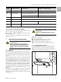
4.2.2 Layout of the electronic components in the
enclosure
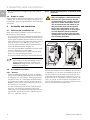
Fig. 3: Never direct the cold airflow at active components
Air diversion components are available as accessories. It
is important to ensure even air circulation inside the en-
closure. Under no circumstances should air inlet and
outlet openings be obstructed, otherwise the cooling
performance of the unit will be reduced. Ensure the dis-
tance "x" (see fig. 4) from electronic components and
other installed enclosures so that the required air circu-
lation is not obstructed and prevented.
Note:
These models are UL Type NEMA 12/3R/4
(outdoor) approved only as installed in the
external mounting position. See section4.3
"Fitting the cooling unit".
Caution! Risk of condensation!
When arranging the components inside
the enclosure, please ensure that the
cold airflow from the cooling unit is not
directed at active components. Please
also ensure that the cold airflow is not
directed at the warm exhaust airflow
from active components such as con-
verters. This may lead to an air shortcir-
cuit and therefore prevent adequate
climate control, or may even cause the
cooling unit’s internal safety devices to
cease cooling operation.

Rittal enclosure cooling unit 13
4 Assembly and connection
EN
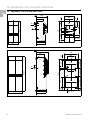
Fig. 4: Air circulation inside the enclosure
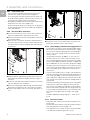
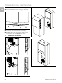
4.3 Fitting the cooling unit
The enclosure cooling unit may be externally mounted
on the enclosure.
Fig. 5: Installation method
To this end, cut the side panel or door of the enclosure
as per the drilling template included with the supply, and
drill the relevant holes.
4.3.1 Cutting out on the enclosure
Stick the supplied drilling template onto the side panel
or door of the enclosure using adhesive tape.
There are dimensioning lines on the drilling template for
your cooling unit (see section10 "Appendix: Cut-out
and hole sizes").
Mark, drill and deburr the holes.
Make the cut-outs including the line width as per the
drilling template.
Deburr the cut-outs.
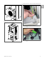
4.3.2 External mounting of the cooling unit
Cut the supplied sealing tape to the correct length and
stick it carefully along the back of the unit so that no
gaps are left at the joints. The joints should be located
at the bottom of the unit.
Fig. 6: Attach the sealing tape
Screw the supplied threaded studs into the blind nuts
on the rear of the unit.
Secure the unit using the supplied washers and nuts.
Fig. 7: Secure the cooling unit
4.4 Notes on electrical installation
When performing the electrical installation, it is important
to observe all valid national and regional regulations as
well as the provisions of the responsible power supply
company. Electrical installation must only be carried out
by a qualified electrician who is responsible for compli-
ance with the existing standards and regulations.
Model No. Dimension x
[mm]
Dimension y
[mm]
3303.xxx 131 200
3304.xxx/3305.xxx 162 200
3329.xxx 184 200
Tab. 1: Dimension "x"
x
y
Risk of injury!
Carefully deburr all drilled holes and cut-
outs to prevent injuries caused by sharp
edges.

4 Assembly and connection
EN
14 Rittal enclosure cooling unit
4.4.1 Connection data
– The connected voltage and frequency must corre-
spond to the values stated on the rating plate.
– The cooling unit must be connected to the mains via
an all-pin isolating device, which ensures at least 1/8"
(3 mm) contact opening when switched off.
– No additional temperature control may be connected
upstream of the unit at the supply end.
– Install a circuit breaker or time delay fuse as specified
on the rating plate to protect the cable and equipment
from short-circuits.
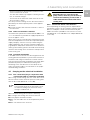
4.4.2 Electrical Box connection
Loosen and remove the two screws and washers on
top of the electrical box and remove the cover.
Remove knockouts from the electrical box to allow for
all required cables.
After the unit is mounted, attach the electrical box to
the rear of the unit. Use the two self threading screws
and the washers from the dispatch box according to
your model.
Fig. 8: Dismantling the cover of the electrical box
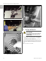
Snap the plastic grommet(s) into the holes for the non-
main power to protect the cables from the edges of
the holes.
Install 1/2" conduit and conduit connector (not includ-
ed) as required for the installation.
Route the main power cable through conduit and into
box leaving a minimum of 6" (152 mm) for lead wire.
Connect the cable to the X1 connector and attach to
unit.
Fig. 9: Attaching the connector to the electrical box
Attach the cover on the electrical box using the two
previously removed screws and washers.
4.4.3 Overvoltage protection and supply line load
– The unit does not have its own overvoltage protection.
Measures must be taken by the operator at the supply
end to ensure effective lightning and overvoltage pro-
tection. The mains voltage must not exceed a toler-
ance of ±10 %.
– In accordance with IEC 61 000-3-11, the unit is in-
tended solely for use at sites with a continuous cur-
rent-carrying capacity (incoming mains power supply)
of more than 100 A per phase and with a supply volt-
age of 400/230/115 V. If necessary, the power supply
company must be consulted to ensure that the contin-
uous current-carrying capacity at the point of connec-
tion to the public grid is sufficient for connection of
such a unit.
– The fans and compressors in single- and threephase
units are intrinsically safe (thermal winding protection).
The same also applies to the transformer versions of
types 3304.5x8, 3305.5x8 and 3329.5x8 and to spe-
cial- voltage units which are likewise equipped with a
transformer.
– Install the time delay fuse specified on the rating plate
to protect the cable and equipment from short-cir-
cuits. Select a suitable circuit-breaker in accordance
with the information specified on the rating plate: Set
it to the minimum specified value. This will achieve the
best short-circuit protection for cables and equip-
ment.
Example: Specified setting range 6.3 – 10 A; set to
6.3 A.
4.4.4 Door limit switch
– Each door limit switch must only be assigned to one
cooling unit.
– Several door limit switches may be connected in par-
allel and operated on one cooling unit.
– The minimum cross-section for the connection cable
is 22 AWG for a cable length of 6.5' (2 m).

Rittal enclosure cooling unit 15
4 Assembly and connection
EN
– The line resistance to the door limit switch must not
exceed a maximum of 50 .
– The door limit switch only supports a floating connec-
tion; no external voltages.
– The contact of the door limit switch must be closed
when the door is open.
The safety extra-low voltage for the door limit switch is
provided by the internal power pack: Current approx.
30 mA DC.
Connect the door limit switch to terminals 1 and 2 of
the connector.
4.4.5 Notes on the flicker standard
The flicker limits specified in standard EN 61 000-3-3 or
-3-11 are adhered to, provided the supply impedance is
less than approx. 1.5 .
Where necessary, the unit operator should measure the
connected impedance or consult the responsible power
supply company. If there is no way of influencing the
supply impedance and sensitive installed components
(e.g. BUS) are subjected to interference, a line reactor or
starting-current limiting device should be connected up-
stream of the cooling unit to restrict the startup current
of the cooling unit.
4.4.6 Potential equalization
If, for EMC reasons, the unit is to be integrated into the
existing potential equalization system at the customer, a
conductor with a larger nominal crosssection can be
connected to the potential equalization connection point
(attachment points) on wallmounted cooling units.
According to the standard, the PE conductor in the
mains connection cable is not classified as an equipo-
tential bonding conductor.
4.5 Carrying out the electrical installation
4.5.1 Bus connection (only in conjunction with
several units with an e-Comfort controller)
When using several cooling units, the serial device inter-
face X2 can be used to connect up to ten cooling units
with the bus cable (Model No. 3124.100).
When interconnecting, please note the following:
De-energize the cooling units to be connected.
Ensure proper electrical insulation.
Make sure the cables are not laid in parallel to power
lines.
Make sure that the lines are short.
4.5.2 Connection X3 for serial interface
For incorporating the cooling unit into superordinate
monitoring systems, the IoT interface, together with the
Blue e IoT adaptor, can be connected to the 9-pole
SUB-D connector (available as accessories: IoT inter-
face Model No. 3124.300, Blue e IoT adaptor Model No.
3124.310).
Note:
The electrical signals at the X2 interface are of
an extra-low voltage (not extra-low safety
voltages to EN 60 335-1).
Caution!
Regarding the last slave unit in the
group, do not, under any circumstances,
connect the remaining socket of the Y
cable 3124.100 into interface X3 of the
cooling unit!

4 Assembly and connection
EN
16 Rittal enclosure cooling unit
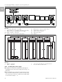
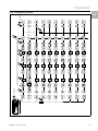
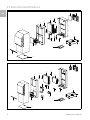
Fig. 10: Connection example: Master-slave operation
Legend
1 IoT Interface (Model No. 3124.300)
2 Blue e adaptor for IoT Interface (Model No. 3124.310)
3 Master-slave bus cable (Model No. 3124.100)
RTT Rittal TopTherm cooling units
X1 Supply connection/door limit switch/alarms
X2 Master/slave connection Sub-D, 9-pole
X3 Serial interface Sub-D, 9-pole
St. Sub-D connector, 9-pole
Bu. Sub-D jack, 9-pole
Adr. Address
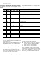
Fig. 11: Connection example: Door limit switch and master-slave operation
Legend
1 Master cooling unit
2 Slave cooling units
3 2-door enclosure with two door limit switches
4 Enclosure with door limit switch
4.5.3 Installing the power supply
Complete the electrical installation by following the
wiring plan on the rear of the cooling unit (see fig. 1 on
page 10).
If you would like the system messages from the cool-
ing unit to be evaluated via the system message relay,
you should also connect a suitable low-voltage cable
to connection clamps 3 – 5.
X2
IoT Interface
Blue e adaptor for
IoT Interface
RTT
Master
Adr.: 09
X1
X2
X3
X1
X2
X3
X1
X2
X3
X1
X2
X3
X2
X3
X2
X2
X2
X2
X2
X2
St. St. St.
Bu.
St.
Bu.
X2
Adr.: 11 Adr.: 12RTT
Slave
RTT
Slave
Adr.: 19RTT
Slave
St.
Bu.
St.
Bu.
3
1
2
X10
L1
L2
N
PE
1
23
4
5
1
X10
X10 X10 X10 X10
X2 X2 X2 X2 X2 X2
X2
L1
PE
1
23
4
5
L1
L2
N
PE
1
23
4
5
L2 L3
L1
PE
1
23
4
5
L2 L3
L1
PE
1
23
4
5
L2 L3
L1
PE
1
23
4
5
L2 L3
L1
L2
N
PE
1
23
4
5
X10
2
3
4
56
1
Adr.: 06 Adr.: 11 Adr.: 12 Adr.: 13 Adr.: 14 Adr.: 15
22 2 2 2
34432
Adr.: 16

Rittal enclosure cooling unit 17
5 Commissioning
EN
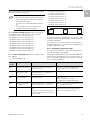
Fig. 12: Electrical wiring plan no. 1
Fig. 13: Electrical wiring plan no. 2
Legend
X1 Main terminal strip
X2 Master/slave connection
X3 Optional interface
K1 Relay collective fault 1
K2 Relay collective fault 2
Door Door limit switch (without door limit switch: terminal 1, 2
open)
5 Commissioning
Once all the assembly and installation work is com-
plete, switch on the power supply to the cooling unit.
The cooling unit starts running:
– The software version of the controller first appears for
approx. 2 sec. Then the enclosure internal tempera-
ture appears in the 7-segment display.
You can now make your individual settings on the unit,
e.g. set the temperature or assign the network identifier,
etc. (refer to section6 "Operation").
6 Operation
You can operate the cooling unit using the controller on
the rear of the device (fig. 1, item 3, page 10)
6.1 Control using the e-Comfort controller
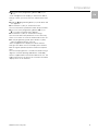
Fig. 14: e-Comfort controller
Key
1 Programming button, also display of the set temperature
unit (degrees Celsius)
2 Set button
3 Programming button, also display of the set temperature
unit (degrees Fahrenheit)
47-segment display
6.1.1 Properties
– Rated operating voltage:
– 115 V or
– 230 V or
– 400/460 V, 3-phase, supports multiple voltages
without rewiring
– Integral start-up delay and door limit switch function
– Monitoring of all motors (compressor, condenser fan,
evaporator fan)
– Phase monitoring for three-phase units
– Master-slave function with a maximum of ten units.
One device functions as a master unit. Once the set
temperature is reached by one of the connected slave
devices or in the event of the door limit switch function,
the affected slave unit will report to the master unit that
switches all the other cooling units on or off as re-
quired.
– Switching hysteresis: adjustable from 2 – 10 K, preset
to 5 K, where 5 K is the hysteresis value.
Note:
For technical data refer to the rating plate.
AC
cos φ = 1
DC
L/R = 20 ms
I max. = 2 A
U max. = 250 V
I min. = 100 mA
U max. = 200 V
U min. = 18 V
I max. = 2 A
Tab. 2: Contact data
Caution! Risk of damage!
The oil must collect in the compressor in
order to ensure effective lubrication and
cooling. Do not operate the cooling unit
for at least 30 min. after assembling the
equipment.
3303.508/3303.518/3304.508/3304.518/3305.518/
3303.518/3329.508/3329.518
3304.548/3305.548/3329.548
12
4
3

6 Operation
EN
18 Rittal enclosure cooling unit
– Visualisation of the current internal enclosure temper-
ature and all error messages in the 7-segment display
– The IoT interface (Model No. 3124.300) together with
the Blue e IoT adaptor (Model No. 3124.310) can be
incorporated into superordinate remote monitoring
systems.
The cooling unit operates automatically, i.e. after switch-
ing on the power supply, the evaporator fan (see fig. 2)
will run and circulate the internal enclosure air. The com-
pressor and condenser fan are regulated by the e-Com-
fort controller. The e-Comfort controller has a 7-seg-
ment display (fig. 14, item 4). After switching on the
power supply, the current software version initially ap-
pears on this display for approx. 2 seconds, followed by
a preset option (e.g. t10) or the temperature.
In regular operation, the display shows both the temper-
ature (in degrees Celsius or Fahrenheit – users may
switch between the two) and any error messages.
The current internal enclosure temperature is usually dis-
played permanently. In the event of an error message,
this alternates with the temperature display.
The unit is programmed using buttons 1 – 3 (fig. 14). The
relevant parameters also appear in the display.
6.1.2 Eco mode
All Rittal TopTherm cooling units with e-Comfort control-
ler from firmware 3.2 have the energy-saving eco mode,
which is disabled in the delivered state of UL Type 12/
3R/4 cooling units. The evaporator fan runs continuous-
ly.
If required, eco mode can be enabled on the control dis-
play. For this purpose switch the parameter from 0 to 1
in the programming level (see tab. 3).
The eco mode is used to save energy in the heat ex-
changer if there is no thermal load, or there is a low ther-
mal load in the enclosure (e. g. standby operation, no
production or weekend). During this process the evapo-
rator fan in the internal circuit is switched off as appro-
priate if the actual internal enclosure temperature drops
to 10 K below the specified setpoint temperature. To en-
sure the internal temperature is reliably measured during
this process, the fan starts cyclically for 30 sec. (see
fig. 15). If the internal temperature drops to a range 5 K
below the setpoint set again, the fan switches back to
continuous operation.
Fig. 15: Eco mode
6.1.3 Launching test mode
The e-Comfort controller is equipped with a test function
whereby the cooling unit commences cooling operation
independently of the set temperature or door limit switch
function.
Simultaneously press buttons 1 and 2 (fig. 14) for at
least 5 sec.
The cooling unit will commence operation. Test mode is
completed after approximately 5 minutes. The unit
switches off and changes to normal operation.
6.1.4 General information about programming
Using buttons 1, 2 and 3 (fig. 14) you can change 24pa-
rameters within the preset ranges (min. value, max. val-
ue).
Tables 3 and 4 show the parameters which can be al-
tered. Fig. 16 on page 21 shows which buttons must be
pressed.
In principle, the programming is identical for all editable
parameters.
To enter programming mode:
Press button 2 ("Set") for approx. 5 seconds.
The controller is now in programming mode. While in
programming mode, if you do not press any buttons for
approx. 30 seconds, the display will first flash, then the
controller will switch back to normal display mode. "Esc"
in the display indicates that any changes made have not
been saved.
Press the programming buttons (°C) or (°F) to
switch between the editable parameters (see tables3
and 4).
Press button 2 ("Set") to select the displayed parame-
ter for editing.
The current value of this parameter is displayed.
ON
Status
internal fan
Internal
temperature
Time
Setpoint
-5 K
Setpoint
-10 K
OFF
10 min.
30 sec.
10 min.
Note on switching hysteresis:
With a low hysteresis and short switching cy-
cles, there is a risk that cooling may not be
adequate or that only partial sections of the
enclosure are cooled. If the cooling unit is
oversized and compressor running times are
<1minute, the switching hysteresis is auto-
matically increased to protect the cooling unit
(see message "LH" in section6.1.9 "Evaluat-
ing system messages").
Note on temperature settings:
With the e-Comfort controller, the tempera-
ture is preset at the factory to 95 °F (+35 °C).
In order to save energy, and due to the risk of
increased condensation, do not set the tem-
perature lower than that actually necessary.
Note on useful cooling power:
Interactive performance diagrams for calcu-
lating the useful cooling power may be found
at www.rittal.com.

Rittal enclosure cooling unit 19
6 Operation
EN
Press one of the programming buttons (°C) or
(°F).
"Cod" will appear in the display. In order to be able to
change a value, you must enter the authorisation code
"22".
Keep the programming button (°C) held down until
"22" appears.
Press button 2 ("Set") to confirm the code.
You can now alter the parameter within the preset limits.
Press one of the programming buttons (°C) or
(°F) until the required value appears.
Press button 2 ("Set") to confirm the change.
You can now alter other parameters in the same way.
There is no need to re-enter the authorisation code "22".
To exit programming mode, press button 2 ("Set")
again for approximately 5 seconds.
"Acc" will appear in the display to indicate that the
changes have been saved. The display then switches
back to regular operation (internal enclosure tempera-
ture).
You can also program the e-Comfort controller using a
diagnosis software package (Model No. 3159.100),
which is supplied with a connection cable to the PC. The
cable connector on the rear of the e-Comfort controller
display serves as an interface.

6 Operation
EN
20 Rittal enclosure cooling unit
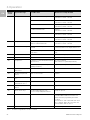
6.1.5 Editable parameters
See also fig. 16 on page 21.
Progr.
level
Display
screen
Parameter Min.
value
Max.
value
Factory
setting
Description
1 St Internal enclosure
temperature set-
point T
i
68 °F 131 °F 95 °F The internal enclosure temperature setting is
preset at the factory to 95 °F (35 °C) and may be
altered within a range of 68 – 131 °F (20 –
55 °C).
2 Fi Filter mat monitor-
ing
10 60 99
(= off)
To enable filter mat monitoring, the display
should be set to a minimum of 10 K above the
temperature difference shown in programming
mode "Fi"; filter mat monitoring is disabled at the
factory (99 = off).
Not applicable for NEMA 3R/4 units!
3 Ad Master-slave
identifier
0 19 0 See section 6.1.8 "Setting the master/slave
identifier"
4 CF Switch between
°C/°F
0 1 0 The temperature display can be switched be-
tween °C (0) and °F (1). The LED displays the
current unit of temperature.
5 H1 Setting for switch-
ing difference
(hysteresis)
2 10 5 The cooling unit is preset in the factory to a
switching hysteresis of 5 K. This parameter
should only be changed in consultation with us.
Please contact us for advice.
6 H2 Differential for er-
ror message A2
3 15 5 If the internal enclosure temperature exceeds
the set value by more than 5 K, then error mes-
sage A2 (internal enclosure temperature too
high) appears on the display terminal. If neces-
sary, the differential may be altered here within
the range of 3 – 15 K.
26 ECO Eco-mode opera-
tion
0 1 0 Eco mode OFF: 0 / Eco mode ON: 1
27 PSO Changing the au-
thorisation code
0 15 0 This parameter allows you to change the "22"
authorisation code (factory setting).
The new code results from the sum of 22 +
PSO.
Tab. 3: Editable parameters
Pagina se încarcă ...
Pagina se încarcă ...
Pagina se încarcă ...
Pagina se încarcă ...
Pagina se încarcă ...
Pagina se încarcă ...
Pagina se încarcă ...
Pagina se încarcă ...
Pagina se încarcă ...
Pagina se încarcă ...
Pagina se încarcă ...
Pagina se încarcă ...
Pagina se încarcă ...
Pagina se încarcă ...
Pagina se încarcă ...
Pagina se încarcă ...
-
 1
1
-
 2
2
-
 3
3
-
 4
4
-
 5
5
-
 6
6
-
 7
7
-
 8
8
-
 9
9
-
 10
10
-
 11
11
-
 12
12
-
 13
13
-
 14
14
-
 15
15
-
 16
16
-
 17
17
-
 18
18
-
 19
19
-
 20
20
-
 21
21
-
 22
22
-
 23
23
-
 24
24
-
 25
25
-
 26
26
-
 27
27
-
 28
28
-
 29
29
-
 30
30
-
 31
31
-
 32
32
-
 33
33
-
 34
34
-
 35
35
-
 36
36


Rittal 3303.508 Assembly And Operating Instructions Manual
- Tip
- Assembly And Operating Instructions Manual
în alte limbi
- English: Rittal 3303.508
Lucrări conexe
-
Rittal SK 3303.470 Assembly And Operating Instructions Manual
-
-
Rittal TP 6746.600 Manual de utilizare
-
Rittal 7979.139 Installation And Short User Manual
-
Rittal AX 1031.000 Compact Control Cabinet Rittal AX Manualul proprietarului
-
-
Rittal SV 9635.020 Manual de utilizare
Alte documente
-
DeLOCK 65503 Fișa cu date
-
-
Ingersoll-Rand R55 Product Maintenance Information
-
Grundfos Conex DIS-D Installation And Operating Instructions Manual
-
Danfoss Optyma Slim Pack EMA Ghid de instalare
-
Brennenstuhl Smart power strips (master/slave strips) 8 x PG connector 1159490946 Manual de utilizare
-
-
Danfoss Optyma Slim Pack OPMSXM034-046 Manual de utilizare
-
Cisco Systems MDS 9500 Manual de utilizare
-