Ingersoll-Rand 77H90L10-EU Informații despre produs
- Tip
- Informații despre produs

16573214
Edition 3
May 2014
Save These Instructions
Product Information
EN
Product Information
Especicaciones del producto
Spécications du produit
Προδιαγραφές προϊόντος
Especicações do Produto
Tuote-erittely
Produktspesikasjoner
Produktspecikationer
Produktspecikationer
Productspecicaties
Technische Produktdaten
Speciche prodotto
Информация за продукта
Informacje o Produkcie
Ierices specikacijas
Gaminio techniniai duomenys
A termék jellemzői
Toote spetsikatsioon
Specikace výrobku
Špecikácie produktu
Specikacije izdelka
ES
FR
IT
DE
NL
DA
SV
NO
FI
PT
EL
SL
SK
CS
ET
HU
LT
LV
PL
BG
Informaţii privind produsul
RO
Технические характеристики изделия
RU
Podaci o proizvodu
HR
Air Grinders
Series 61H, 77H, 88H and 99H

2 16573214_ed3
4
7
5
3
2
1
6
48h
24h
9
10
PMAX
8
11
8h
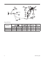
(Dwg. 16573412)
Model(s)
1
3
2
5
6
10
11
IR # - NPT IR # - BS inch (mm) NPT IR # IR #
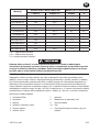
Series 61H, 77H C38341-810 C383D1-810 1/2 (13) 3/8 50 50
Series 88H, 99H C38351-810 C383E1-810 3/4 (19) 1/2 50 50

16573214_ed3 EN-1
EN
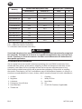
Product Safety Information
Intended Use:
These Air Grinders are designed for material removal or cutting o using a rotated abrasive
wheel, in accordance with the product specication table.
WARNING
Failure to observe the following warnings, and to avoid these potentially hazardous
situations, could result in death or serious injury.
Always turn o the air supply, bleed the air pressure and disconnect the air supply hose
when not in use, before installing, removing or adjusting any accessory on this tool, or
before performing any maintenance on this tool or any accessory.
Do not attempt to disassemble the internal Speed Controller. It is available only as a
unit.
Before installing a new Arbor Housing Assembly, always select the correct Nameplate
Kit and secure it to the Arbor Housing with the Nameplate Screws.
For additional information refer to Product Safety Information Manual Form 04584959.
Manuals can be downloaded from ingersollrandproducts.com
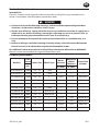
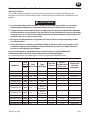
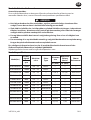
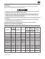
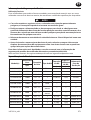
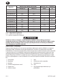
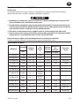
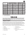
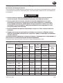
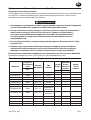
Product Specications
Model(s)
Free
Speed
Arbor Size Wheel Type
Wheel
Diameter
Maximum
Wheel
Thickness
Guard Part
Number
rpm
in. (mm) in. (mm)
61H120L6-EU 12000 3/8” - 24 Cone --- --- ---
61H150L6-EU 15000 3/8” - 24 Cone --- --- ---
61H120H63-EU 12000 3/8” - 24 1 3 (76.2) 1/2 (13) 61H-931A
77H120H84-EU 12000 1/2” - 13 1 4 (101.6) 1 (25) 77H-941
77H90L10-EU 9000 5/8” - 11 Cone --- --- ---
77H120L10-EU 12000 5/8” - 11 Cone --- --- ---
77H30B106-EU 3000 5/8” - 11 Wire Brush --- --- ---
77H50B106-EU 5000 5/8” - 11 Wire Brush --- --- ---
88HL60H106-EU 6000 5/8” - 11 1 6 (152) 1 (25) 88H60-961A
88HG60H106-EU 6000 5/8” - 11 1 6 (152) 1 (25) 88H60-961A
99HL45H108-EU 4500 5/8” - 11 1 8 (203) 1 (25) 9H45-981
99HL60H106-EU 6000 5/8” - 11 1 6 (152) 1 (25) 99H45-981
●
●
●
●

EN-2 16573214_ed3
EN
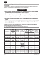
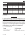
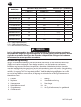
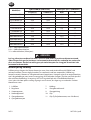
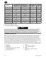
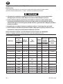
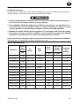
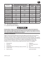
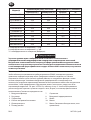
Model(s)
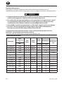
Sound Level dB(A) (ISO15744) Vibration (m/s²) (ISO28927)
† Pressure (L
p
) ‡ Power (L
w
) Level *K
61H120L6-EU 83.3 94.3
<2.5 ---
61H150L6-EU 86.8 97.8
<2.5 ---
61H120H63-EU 83.6 94.6
<2.5 ---
77H120H84-EU 82.4 93.4
2.8 1.2
77H90L10-EU 77.9 --
<2.5 ---
77H120L10-EU 82.4 93.4
4.2 3.5
77H30B106-EU 82.2 93.2
5.9 2.1
77H50B106-EU 91.4 102.4
7.8 2.7
88HL60H106-EU 76.4 --
<2.5 ---
88HG60H106-EU 76.4 --
<2.5 ---
99HL45H108-EU 79.0 --
<2.5 ---
99HL60H106-EU 82.8 93.8
<2.5 ---
† K
pA
= 3dB measurement uncertainty
‡ K
wA
= 3dB measurement uncertainty
* K = Vibration measurement uncertainty
WARNING
Sound and vibration values were measured in compliance with internationally recognized
test standards. The exposure to the user in a specic tool application may vary from these
results. Therefore, on site measurements should be used to determine the hazard level in
that specic application.
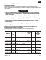
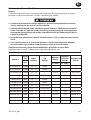
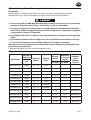
Installation and Lubrication
Size air supply line to ensure tool’s maximum operating pressure (PMAX) at tool inlet. Drain
condensate from valve(s) at low point(s) of piping, air lter and compressor tank daily. Install
a properly sized Safety Air Fuse upstream of hose and use an anti-whip device across any
hose coupling without internal shut-o, to prevent hose whipping if a hose fails or coupling
disconnects. See drawing 16573412 and table on page 2. Maintenance frequency is shown in a
circular arrow and dened as h=hours, d=days, and m=months of actual use. Items identied as:
1. Air lter 7. Coupling
2. Regulator 8. Safety Air Fuse
3. Lubricator 9. Hose Whip
4. Emergency shut-o valve 10. Oil
5. Hose diameter 11. Oil (Fill Oil Chamber, if applicable.)
6. Thread size

16573214_ed3 EN-3
EN
Parts and Maintenance
When the life of the tool has expired, it is recommended that the tool be disassembled,
degreased and parts be separated by material so that they can be recycled.
Original instructions are in English. Other languages are a translation of the original instructions.
Tool repair and maintenance should only be carried out by an authorized Service Center.
Refer all communications to the nearest Ingersoll Rand Oce or Distributor.

ES-1 16573214_ed3
ES
Información de Seguridad Sobre el Producto
Uso Indicado:
Estas amoladoras neumáticas están diseñadas para eliminar material mediante un accesorio
rotatorio, de acuerdo con la tabla de especicaciones del producto.
ADVERTENCIA
No observar las siguientes advertencias y no evitar estas situaciones potencialmente
peligrosas podría causar lesiones graves o incluso la muerte.
Corte siempre el suministro de aire, purgue la presión de aire y desconecte la manguera
de suministro de aire antes de instalar, desmontar o ajustar cualquier accesorio de esta
herramienta, o antes de realizar cualquier operación de mantenimiento en la herrami-
enta o en cualquier accesorio.
No intente desacoplar el controlador interno de velocidad. Sólo está disponible como
unidad.
Antes de instalar un nuevo montaje de alojamientos de eje, seleccione siempre el kit de
placas de identicación correcto y fíjelo al alojamiento del eje con los tornillos de las
placas de identicación.
Para más información, consulte el Manual de información de seguridad de producto
04584959 Amoladora de matrices neumática.
Los manuales pueden descargarse en ingersollrandproducts.com
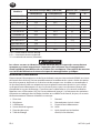
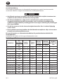
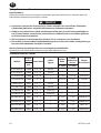
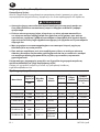
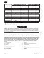
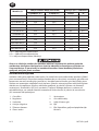
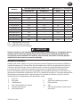
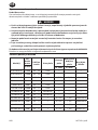
Especicaciones del Producto
Modelo(s)
Libre
Velocidad
Tamañ
o de eje
Tipo
de Muela
Tamaño
de
Muela
Grosor
Máximo de la
Muela
Número
de Pieza
del Protector
rpm
in. (mm) in. (mm)
61H120L6-EU 12000 3/8” - 24 Cono --- --- ---
61H150L6-EU 15000 3/8” - 24 Cono --- --- ---
61H120H63-EU 12000 3/8” - 24 1 3 (76.2) 1/2 (13) 61H-931A
77H120H84-EU 12000 1/2” - 13 1 4 (101.6) 1 (25) 77H-941
77H90L10-EU 9000 5/8” - 11 Cono --- --- ---
77H120L10-EU 12000 5/8” - 11 Cono --- --- ---
77H30B106-EU 3000 5/8” - 11
Cepillo de
alambre
--- --- ---
77H50B106-EU 5000 5/8” - 11
Cepillo de
alambre
--- --- ---
88HL60H106-EU 6000 5/8” - 11 1 6 (152) 1 (25) 88H60-961A
88HG60H106-EU 6000 5/8” - 11 1 6 (152) 1 (25) 88H60-961A
99HL45H108-EU 4500 5/8” - 11 1 8 (203) 1 (25) 9H45-981
99HL60H106-EU 6000 5/8” - 11 1 6 (152) 1 (25) 99H45-981
●
●
●
●

16573214_ed3 ES-2
ES
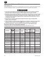
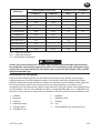
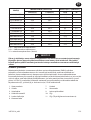
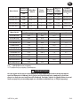
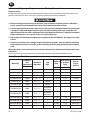
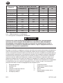
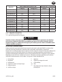
Modelo(s)
Nivel Sonoro dB(A) (ISO15744) Vibración (m/s²) (ISO28927)
† Presión (L
p
) ‡ Potencia (L
w
) Nivel *K
61H120L6-EU 83.3 94.3
<2.5 ---
61H150L6-EU 86.8 97.8
<2.5 ---
61H120H63-EU 83.6 94.6
<2.5 ---
77H120H84-EU 82.4 93.4
2.8 1.2
77H90L10-EU 77.9 --
<2.5 ---
77H120L10-EU 82.4 93.4
4.2 3.5
77H30B106-EU 82.2 93.2
5.9 2.1
77H50B106-EU 91.4 102.4
7.8 2.7
88HL60H106-EU 76.4 --
<2.5 ---
88HG60H106-EU 76.4 --
<2.5 ---
99HL45H108-EU 79.0 --
<2.5 ---
99HL60H106-EU 82.8 93.8
<2.5 ---
† K
pA
= 3dB de error
‡ K
wA
= 3dB de error
* K = de error (Vibración)
ADVERTENCIA
Los valores de ruido y vibración se han medido de acuerdo con los estándares para prue-
bas reconocidos internacionalmente. Es posible que la exposición del usuario en una apli-
cación especíca de herramienta diera de estos resultados. Por lo tanto, la mediciones in
situ se deberían utilizar para determinar el nivel de riesgo en esa aplicación especíca.
Instalación y Lubricación
Diseñe la línea de suministro de aire para asegurar la máxima presión de funcionamiento (PMAX)
en la entrada de la herramienta. Vacíe el condensado de las válvulas en los puntos inferiores de
la tubería, ltro de aire y depósito del compresor de forma diaria. Instale una contracorriente de
manguera de fusil de aire de seguridad de tamaño adecuado y utilice un dispositivo antilatigazos
en cualquier acoplamiento de manguera sin apagador interno para evitar que las mangueras
den latigazos en caso de que una manguera falle o de que el acoplamiento se desconecte.
Consulte la dibujo 16573412 y la tabla en la página 2. La frecuencia de mantenimiento se
muestra dentro de una echa circular y se dene como h = horas, d = días y m = meses de uso
real. Los elementos se identican como:
1. Filtro de aire 7. Acoplamiento
2. Regulador 8. Fusil de aire de seguridad
3. Lubricador 9. Manguito de manguera
4. Válvula de corte de emergencia 10. Aceite
5. Diámetro de la manguera 11. Aceite (Si es necesario, rellene la cámara
6. Tamaño de la rosca de aceite)

ES-3 16573214_ed3
ES
Piezas y Mantenimiento
Una vez vencida la vida útil de herramienta, se recomienda desarmar la herramienta,
desengrasarla y separar las piezas de acuerdo con el material del que están fabricadas para
reciclarlas.
Las instrucciones originales están en inglés. Las demás versiones son una traducción de las
instrucciones originales.
Las labores de reparación y mantenimiento de las herramientas sólo puede ser realizadas por un
Centro de Servicio Autorizado.
Toda comunicación se deberá dirigir a la ocina o al distribuidor Ingersoll Rand más próximo.

16573214_ed3 FR-1
FR
Informations de Sécurité du Produit
Utilisation Prévue:
Ces meuleuses pneumatiques sont conçues pour enlever de la matière ou eectuer des
découpes à l’aide d’un disque abrasif rotatif, conformément au tableau des spécications de
produit.
AVERTISSEMENT
Le non-respect des avertissements suivants et le fait de ne pas éviter ces situations
potentiellement dangereuses peuvent entraîner la mort ou des blessures graves.
Coupez toujours l’alimentation en air, purgez la pression d’air et débranchez le exible
de l’alimentation en air quand il n’est pas utilisé, avant d’installer, de retirer ou de régler
un accessoire sur cet outil ou avant d’entreprendre toute opération de maintenance sur
le produit ou sur l’un de ses accessoires.
N’essayez pas de démonter le régulateur de vitesse interne. Uniquement disponible
sous forme de kit.
Avant d’installer un nouvel assemblage de boîtier d’arbres, choisissez toujours le kit
contenant la plaque signalétique correspondante et sécurisez-le au boîtier d’arbres
avec les vis de la plaque signalétique.
Pour des informations complémentaires, reportez-vous au manuel 04584959
d’information de sécurité du produit Meuleuse pneumatique légère.
Les manuels peuvent être téléchargés à l’adresse ingersollrandproducts.com
Spécications du Produit
Modèle(s)
Libre
Vitesse
Taille
de L’arbre
Type
de Disque
Taille de
Disque
Epaiss
eur Maximale
du Disque
Numéro de
Pièce du
Protecteur
rpm
in. (mm) in. (mm)
61H120L6-EU 12000 3/8” - 24 Cône --- --- ---
61H150L6-EU 15000 3/8” - 24 Cône --- --- ---
61H120H63-EU 12000 3/8” - 24 1 3 (76.2) 1/2 (13) 61H-931A
77H120H84-EU 12000 1/2” - 13 1 4 (101.6) 1 (25) 77H-941
77H90L10-EU 9000 5/8” - 11 Cône --- --- ---
77H120L10-EU 12000 5/8” - 11 Cône --- --- ---
77H30B106-EU 3000 5/8” - 11
Brosse
métallique
--- --- ---
77H50B106-EU 5000 5/8” - 11
Brosse
métallique
--- --- ---
88HL60H106-EU 6000 5/8” - 11 1 6 (152) 1 (25) 88H60-961A
88HG60H106-EU 6000 5/8” - 11 1 6 (152) 1 (25) 88H60-961A
99HL45H108-EU 4500 5/8” - 11 1 8 (203) 1 (25) 9H45-981
99HL60H106-EU 6000 5/8” - 11 1 6 (152) 1 (25) 99H45-981
●
●
●
●

FR-2 16573214_ed3
FR
Modèle(s)
NiveauAcoustique dB(A) (ISO15744) Vibration (m/s²) (ISO28927)
† Pression (L
p
) ‡ Puissance (L
w
) Niveau *K
61H120L6-EU 83.3 94.3
<2.5 ---
61H150L6-EU 86.8 97.8
<2.5 ---
61H120H63-EU 83.6 94.6
<2.5 ---
77H120H84-EU 82.4 93.4
2.8 1.2
77H90L10-EU 77.9 --
<2.5 ---
77H120L10-EU 82.4 93.4
4.2 3.5
77H30B106-EU 82.2 93.2
5.9 2.1
77H50B106-EU 91.4 102.4
7.8 2.7
88HL60H106-EU 76.4 --
<2.5 ---
88HG60H106-EU 76.4 --
<2.5 ---
99HL45H108-EU 79.0 --
<2.5 ---
99HL60H106-EU 82.8 93.8
<2.5 ---
† K
pA
= incertitude de mesure de 3dB
‡ K
wA
= incertitude de mesure de 3dB
* K = incertitude de mesure (Vibration)
AVERTISSEMENT
Les valeurs sonores et vibratoires ont été mesurées dans le respect des normes de tests
reconnues au niveau international. L’exposition de l’utilisateur lors d’une application
d’outil spécique peut diérer de ces résultats. Par conséquent, il faut utiliser des mesures
sur site an de déterminer le niveau de risque de cette application spécique.
Installation et Lubrication
Dimensionnez l’alimentation en air de façon à obtenir une pression maximale (PMAX) au niveau
de l’entrée d’air de l’outil. Drainez quotidiennement le condensat des vannes situées aux points
bas de la tuyauterie, du ltre à air et du réservoir du compresseur. Installez un raccordement à
air de sûreté dont la taille est adaptée au tuyau et placez-le en amont de celui-ci, puis utilisez
un dispositif anti-débattement sur tous les raccords pour tuyaux sans fermeture interne, an
d’empêcher les tuyaux de fouetter si l’un d’entre eux se décroche ou si le raccord se détache.
Reportez-vous à l’illustration 16573412 et au tableau de la page 2. La fréquence des opérations
d’entretien est indiquée dans la èche circulaire et est dénie en h=heures, d=jours, et m=mois
de fonctionnement. Eléments identiés en tant que:
1. Filtre à air 7. Raccord
2. Régulateur 8. Raccordement à air de sûreté
3. Lubricateur 9. Dispositif anti-débattement
4. Vanne d’arrêt d’urgence 10. Huile
5. Diamètre du tuyau 11. Huile (remplissez la chambre
6. Taille du letage d’huile, le cas échéant)

16573214_ed3 FR-3
FR
Pièces détachées et Maintenance
A la n de sa durée de vie, il est recommandé de démonter l’outil, de dégraisser les pièces et de
les séparer en fonction des matériaux de manière à ce que ces derniers puissent être recyclés.
Les instructions d’origine sont en anglais. Les autres langues sont une traduction des instructions
d’origine.
La réparation et la maintenance des outils ne devraient être réalisées que par un centre de
services autorisé.
Adressez toutes vos communications au Bureau Ingersoll Rand ou distributeur le plus proche.

IT-1 16573214_ed3
IT
Informazioni sulla Sicurezza del Prodotto
Destinazione D’uso:
Queste smerigliatrici pneumatiche sono progettate per rimuovere e ritagliare il materiale tramite
un accessorio abrasivo rotante, secondo la tabella contenente le speciche del prodotto.
AVVERTIMENTO
Il mancato rispetto delle seguenti avvertenze, intese a evitare le situazioni potenzial-
mente pericolose indicate di seguito, può dar luogo a infortuni gravi o mortali.
Disattivare sempre la mandata dell’aria, scaricare la pressione dell’aria e staccare il tubo
di alimentazione dell’aria prima di installare, rimuovere o regolare qualsiasi accessorio
su questo utensile e prima di eseguire qualsiasi operazione di manutenzione su di esso
o su qualsiasi accessorio.
Non tentare di smontare il dispositivo di controllo velocità interno. È disponibile
soltanto come unità singola.
Prima di installare un nuovo gruppo alloggiamento mandrino, selezionare sempre il kit
targhetta dati corretto e ssarlo all’alloggiamento mandrino con le apposite viti.
Per ulteriori informazioni, vedasi Fresatrice pneumatica per stampi Manuale delle
Informazioni sulla sicurezza del prodotto 04584959.
I manuali possono essere scaricati da internet al sito ingersollrandproducts.com
Speciche Prodotto
Modello/i
Libero
Velocità
Dimensioni
Mandrino
Tipo di
Mola
Dimensioni
Mola
Massimo
spessor e
Mola
Matricola
Protezione
rpm
in. (mm) in. (mm)
61H120L6-EU 12000 3/8” - 24 Cono --- --- ---
61H150L6-EU 15000 3/8” - 24 Cono --- --- ---
61H120H63-EU 12000 3/8” - 24 1 3 (76.2) 1/2 (13) 61H-931A
77H120H84-EU 12000 1/2” - 13 1 4 (101.6) 1 (25) 77H-941
77H90L10-EU 9000 5/8” - 11 Cono --- --- ---
77H120L10-EU 12000 5/8” - 11 Cono --- --- ---
77H30B106-EU 3000 5/8” - 11
Spazzola
metallica
--- --- ---
77H50B106-EU 5000 5/8” - 11
Spazzola
metallica
--- --- ---
88HL60H106-EU 6000 5/8” - 11 1 6 (152) 1 (25) 88H60-961A
88HG60H106-EU 6000 5/8” - 11 1 6 (152) 1 (25) 88H60-961A
99HL45H108-EU 4500 5/8” - 11 1 8 (203) 1 (25) 9H45-981
99HL60H106-EU 6000 5/8” - 11 1 6 (152) 1 (25) 99H45-981
●
●
●
●

16573214_ed3 IT-2
IT
Modello/i
Livello di Rumorosità dB(A) (ISO15744) Vibrazioni (m/s²) (ISO28927)
† Pressione (L
p
) ‡ Potenza (L
w
) Livello *K
61H120L6-EU 83.3 94.3
<2.5 ---
61H150L6-EU 86.8 97.8
<2.5 ---
61H120H63-EU 83.6 94.6
<2.5 ---
77H120H84-EU 82.4 93.4
2.8 1.2
77H90L10-EU 77.9 --
<2.5 ---
77H120L10-EU 82.4 93.4
4.2 3.5
77H30B106-EU 82.2 93.2
5.9 2.1
77H50B106-EU 91.4 102.4
7.8 2.7
88HL60H106-EU 76.4 --
<2.5 ---
88HG60H106-EU 76.4 --
<2.5 ---
99HL45H108-EU 79.0 --
<2.5 ---
99HL60H106-EU 82.8 93.8
<2.5 ---
† K
pA
= incertezza misurazione 3dB
‡ K
wA
= incertezza misurazione 3dB
* K = incertezza misurazione (Vibrazioni)
AVVERTIMENTO
I valori relativi a suoni e vibrazioni sono stati misurati in conformità agli standard di test
riconosciuti a livello internazionale. L’esposizione all’utente nell’applicazione di uno
specico strumento può variare rispetto ai presenti risultati. Pertanto, sarebbe necessario
utilizzare le misurazioni in loco per determinare il livello di pericolo della specica ap-
plicazione.
Installazione e Lubricazione
La linea di alimentazione dell’aria deve essere dimensionata in maniera tale da assicurare
all’utensile la massima pressione di esercizio (PMAX) in ingresso. Scaricare quotidianamente la
condensa dalla valvola o dalle valvole sulla parte bassa della tubatura, dal ltro dell’aria e dal
serbatoio del compressore. Installare un fusibile di sicurezza di dimensioni adatte a monte del
tubo essibile e utilizzare un dispositivo antivibrazioni su tutti i manicotti senza arresto interno
per evitare i colpi di frusta dei essibili, se questi si guastano o se si staccano gli accoppiamenti.
Vedere il disegno 16573412 e la tabella a pagina 2. La frequenza di manutenzione viene
illustrata da una freccia circolare e denita con h=ore, d=giorni (days) e m=mesi di uso eettivo.
Componenti:
1. Filtro aria 7. Accoppiamento
2. Regolatore 8. Fusibile di sicurezza
3. Lubricatore 9. Tubo essibile
4. Valvola di arresto di emergenza 10. Olio
5. Diametro tubo essibile 11. Olio (rabboccare il serbatoio
6. Dimensione della lettatura dell’olio, se presente)

IT-3 16573214_ed3
IT
Ricambi e Manutenzione
Quando l’attrezzo diventato inutilizzabile, si raccomanda di smontarlo, sgrassarlo e separare i
componenti secondo i materiali in modo da poterli riciclare.
Le istruzioni originali sono in lingua inglese. Le altre lingue sono una traduzione delle istruzioni
originali.
Riparazioni e manutenzione degli utensili devono essere eseguite esclusivamente da un Centro
di Assistenza Autorizzato.
Indirizzare tutte le comunicazioni al più vicino concessionario od ucio Ingersoll Rand.

16573214_ed3 DE-1
DE
Hinweise zur Produktsicherheit
Vorgesehene Verwendung:
Diese Druckluft-Schleifmaschinen wurden dazu entwickelt, in Übereinstimmung mit der
Produkt-Spezikationstabelle mit einem sich drehenden Schleifmittel Material zu entfernen oder
abzuschneiden.
WARNUNG
Wenn Sie die folgenden Warnhinweise nicht beachten und die erwähnten potenziell
gefährlichen Situationen nicht vermeiden, kann dies schwere Verletzungen oder den
Tod zur Folge haben.
Stellen Sie stets die Druckluftzufuhr ab, lassen Sie den Luftdruck ab, und trennen Sie
den Luftversorgungsschlauch vom Werkzeug, bevor jegliche Zubehörteile an diesem
Werkzeug montiert, demontiert oder eingestellt werden oder bevor jegliche Wartung-
sarbeiten am Werkzeug oder an Zubehörteilen durchgeführt werden.
Nicht versuchen, den internen Drehzahlregler auseinander zu bauen. Er ist nur als
Einheit erhältlich.
Vor der Installation einer neuen Wellengehäusebaugruppe immer den korrekten
Bezeichnungsschildsatz auswählen und mit den entsprechenden Schrauben am
Gehäuse befestigen.
Weitere Informationen entnehmen Sie dem Produktsicherheits-Handbuch für die
DruckluftWerkzeugschleifmaschine 04584959.
Handbücher können von ingersollrandproducts.com heruntergeladen werden.
Technische Daten
Modell(e)
Freie
Drehzahl
Wellen-
größe
Wellengröße
Scheibentyp
Scheiben-
größe
Maximale
Scheibe
nstärke
Teile
Nummer
Schutz
rpm
in. (mm) in. (mm)
61H120L6-EU 12000 3/8” - 24 Konus --- --- ---
61H150L6-EU 15000 3/8” - 24 Konus --- --- ---
61H120H63-EU 12000 3/8” - 24 1 3 (76.2) 1/2 (13) 61H-931A
77H120H84-EU 12000 1/2” - 13 1 4 (101.6) 1 (25) 77H-941
77H90L10-EU 9000 5/8” - 11 Konus --- --- ---
77H120L10-EU 12000 5/8” - 11 Konus --- --- ---
77H30B106-EU 3000 5/8” - 11 Drahtbürste --- --- ---
77H50B106-EU 5000 5/8” - 11 Drahtbürste --- --- ---
88HL60H106-EU 6000 5/8” - 11 1 6 (152) 1 (25) 88H60-961A
88HG60H106-EU 6000 5/8” - 11 1 6 (152) 1 (25) 88H60-961A
99HL45H108-EU 4500 5/8” - 11 1 8 (203) 1 (25) 9H45-981
99HL60H106-EU 6000 5/8” - 11 1 6 (152) 1 (25) 99H45-981
●
●
●
●

DE-2 16573214_ed3
DE
Modell(e)
Schallpegel dB(A) (ISO15744) Schwingungs (m/s²) (ISO28927)
† Druck (L
p
) ‡ Stromzufuhr (L
w
) Spegel *K
61H120L6-EU 83.3 94.3
<2.5 ---
61H150L6-EU 86.8 97.8
<2.5 ---
61H120H63-EU 83.6 94.6
<2.5 ---
77H120H84-EU 82.4 93.4
2.8 1.2
77H90L10-EU 77.9 --
<2.5 ---
77H120L10-EU 82.4 93.4
4.2 3.5
77H30B106-EU 82.2 93.2
5.9 2.1
77H50B106-EU 91.4 102.4
7.8 2.7
88HL60H106-EU 76.4 --
<2.5 ---
88HG60H106-EU 76.4 --
<2.5 ---
99HL45H108-EU 79.0 --
<2.5 ---
99HL60H106-EU 82.8 93.8
<2.5 ---
† K
pA
= 3dB Messunsicherheit
‡ K
wA
= 3dB Messunsicherheit
* K = Messunsicherheit (Schwingungs)
WARNUNG
Schall- und Vibrationswerte wurden gemäß den international anerkannten Teststandards
gemessen. Die tatsächlichen Werte, denen der Benutzer während der Anwendung eines
bestimmten Werkzeugs ausgesetzt ist, können von diesen Ergebnissen abweichen. Vor
Ort sollten daher Maßnahmen getroen werden, um die Gefahrenstufe der jeweiligen
Anwendung zu bestimmen.
Montage und Schmierung
Druckluftzufuhrleitung an der Druckluftzufuhr des Werkzeugs gemäß des maximalen
Betriebsdrucks (PMAX) bemessen. Kondensat an den Ventilen an Tiefpunkten von Leitungen,
Luftlter und Kompressortank täglich ablassen. Eine Sicherheits- Druckluftsicherung gegen die
Strömungsrichtung im Schlauch und eine Anti- Schlagvorrichtung an jeder Verbindung ohne
interne Sperre installieren, um ein Peitschen des Schlauchs zu verhindern, wenn ein Schlauch
fehlerhaft ist oder sich eine Verbindung löst. Siehe Zeichnung 16573412 und Tabelle auf Seite 2.
Die Wartungshäugkeit mit einem Pfeil eingekreist und ist deniert in h=Stunden, d=Tagen und
m=Monaten der tatsächlichen Verwendung. Teile:
1. Luftlter 7. Verbindung
2. Regler 8. Sicherheits-Druckluftsicherung
3. Schmierbüchse 9. Schlauchschlag
4. Notabsperrventil 10. Ölen
5. Schlauchdurchmesser 11. Ölen (Wenn zutreend die
6. Gewindegröße Ölkammer füllen)

16573214_ed3 DE-3
DE
Teile und Wartung
Zur Entsorgung ist das Werkzeug vollständig zu demontieren, zu entfetten und nach
Materialarten getrennt der Wiederverwertung zuzuführen.
Die Originalanleitung ist in englischer Sprache verfasst. Bei anderen Sprachen handelt es sich um
ein Übersetzung der Originalanleitung.
Die Werkzeug-Reparatur und -Wartung darf nur von einem autorisierten Wartungszentrum
durchgeführt werden.
Wenden Sie sich bei Rückfragen an Ihre nächste Ingersoll Rand Niederlassung oder den
autorisierten Fachhandel.

NL-1 16573214_ed3
NL
Productveiligheidsinformatie
Bedoeld Gebruik:
Deze pneumatische slijpmachines zijn bedoeld om materiaal te verwijderen of weg te snijden
met behulp van een roterende slijpschijf, overeenkomstig de productspecicatietabel.
WAARSCHUWING
Wanneer u de volgende waarschuwingen niet naleeft en dus mogelijk gevaarlijke situa-
ties voorkomt, kan dit leiden tot de dood of ernstig letsel.
Schakel altijd de luchttoevoer uit, laat de luchtleiding leeglopen en koppel de lucht-
toevoerleiding los wanneer u het apparaat niet gebruikt, accessoires plaatst, aanpast of
verwijdert, of voordat u onderhoud aan dit apparaat of aan een accessoire uitvoert.
Probeer niet om de interne snelheidsregelaar te demonteren. De regelaar is alleen
leverbaar als eenheid.
Selecteer altijd de juiste naamplaatset voordat u een nieuwe behuizing voor de hoofdas
monteert en bevestig de plaat op de behuizing met behulp van de naamplaatschro-
even.
Raadpleeg de productveiligheidshandleiding 04584959 van de pneumatische
matrijzenslijpmachine voor aanvullende informatie.
Handleidingen kunnen worden gedownload vanaf ingersollrandproducts.com
Produktspesikasjoner
Model(len)
Onbelaste
Toerental
Afmeting
Hoofdas
Schijftype
Afmeting
Schijf
Maximale
Schijfdikte
Onderdeelnu
mmer
Beschermkap
rpm
in. (mm) in. (mm)
61H120L6-EU 12000 3/8” - 24 Kegel --- --- ---
61H150L6-EU 15000 3/8” - 24 Kegel --- --- ---
61H120H63-EU 12000 3/8” - 24 1 3 (76.2) 1/2 (13) 61H-931A
77H120H84-EU 12000 1/2” - 13 1 4 (101.6) 1 (25) 77H-941
77H90L10-EU 9000 5/8” - 11 Kegel --- --- ---
77H120L10-EU 12000 5/8” - 11 Kegel --- --- ---
77H30B106-EU 3000 5/8” - 11 Staalborstel --- --- ---
77H50B106-EU 5000 5/8” - 11 Staalborstel --- --- ---
88HL60H106-EU 6000 5/8” - 11 1 6 (152) 1 (25) 88H60-961A
88HG60H106-EU 6000 5/8” - 11 1 6 (152) 1 (25) 88H60-961A
99HL45H108-EU 4500 5/8” - 11 1 8 (203) 1 (25) 9H45-981
99HL60H106-EU 6000 5/8” - 11 1 6 (152) 1 (25) 99H45-981
●
●
●
●

16573214_ed3 NL-2
NL
Model(len)
Geluidsniveau dB(A) (ISO15744) Trillings (m/s²) (ISO28927)
† Druk (L
p
) ‡ Vermogen (L
w
) Niveau *K
61H120L6-EU 83.3 94.3
<2.5 ---
61H150L6-EU 86.8 97.8
<2.5 ---
61H120H63-EU 83.6 94.6
<2.5 ---
77H120H84-EU 82.4 93.4
2.8 1.2
77H90L10-EU 77.9 --
<2.5 ---
77H120L10-EU 82.4 93.4
4.2 3.5
77H30B106-EU 82.2 93.2
5.9 2.1
77H50B106-EU 91.4 102.4
7.8 2.7
88HL60H106-EU 76.4 --
<2.5 ---
88HG60H106-EU 76.4 --
<2.5 ---
99HL45H108-EU 79.0 --
<2.5 ---
99HL60H106-EU 82.8 93.8
<2.5 ---
† Meetonnauwkeurigheid bij K
pA
= 3dB
‡ Meetonnauwkeurigheid bij K
wA
= 3dB
* Meetonnauwkeurigheid bij K (Trillings) K
WAARSCHUWING
Geluids- en vibratiewaarden worden gemeten in overeenstemming met internationaal
erkende testnormen. De blootstelling van een gebruiker bij een specieke toepassing van
gereedschap kan afwijken van deze resultaten. Daarom moeten er op locatie metingen
worden genomen om het gevaarniveau in die specieke toepassing te bepalen.
Installatie en Smering
Om de maximale bedrijfsdruk ( Pmax) bij de luchtinlaat van het toestel te garanderen, moet
de luchttoevoerleiding hierop geselecteerd zijn. Tap dagelijks condensaat af van kleppen bij
lage punten van het leidingwerk, de luchtlter en de compressortank. Monteer een beveiliging
met de juiste afmeting bovenstrooms van de slang en gebruik een antislingerinrichting op
elke slangkoppeling zonder interne afsluiter om te voorkomen dat de slang gaat slingeren
als een slang valt of een koppeling losraakt. Zie tekening 16573412 en tabel op pagina 2. De
onderhoudsfrequentie wordt weergegeven in een cirkelvormige pijl met h=uren, d=dagen
en m=maanden reëel gebruik. Aangegeven onderdelen:
1. Luchtlter 7. Koppeling
2. Regelaar 8. Beveiliging
3. Smeerinrichting 9. Antislingerslang
4. Noodafsluitklep 10. Olie
5. Slangdiameter 11. Olie (Vul de oliekamer,
6. Soort van schroefdraad indien van toepassing)

NL-3 16573214_ed3
NL
Onderdelen en Onderhoud
Wanneer de levensduur van het gereedschap verstreken is, wordt u aangeraden het
gereedschap te demonteren en ontvetten, en de delen gescheiden naar materialen op te bergen
zodat zij gerecycled kunnen worden.
De originele instructies zijn opgesteld in het Engels. Andere talen zijn een vertaling van de
originele instructies.
Reparatie en onderhoud van dit gereedschap mogen uitsluitend door een erkend
servicecentrum worden uitgevoerd.
Richt al uw communicatie tot het dichtsbijzijnde Ingersoll Rand Kantoor of Wederkoper.
Pagina se încarcă...
Pagina se încarcă...
Pagina se încarcă...
Pagina se încarcă...
Pagina se încarcă...
Pagina se încarcă...
Pagina se încarcă...
Pagina se încarcă...
Pagina se încarcă...
Pagina se încarcă...
Pagina se încarcă...
Pagina se încarcă...
Pagina se încarcă...
Pagina se încarcă...
Pagina se încarcă...
Pagina se încarcă...
Pagina se încarcă...
Pagina se încarcă...
Pagina se încarcă...
Pagina se încarcă...
Pagina se încarcă...
Pagina se încarcă...
Pagina se încarcă...
Pagina se încarcă...
Pagina se încarcă...
Pagina se încarcă...
Pagina se încarcă...
Pagina se încarcă...
Pagina se încarcă...
Pagina se încarcă...
Pagina se încarcă...
Pagina se încarcă...
Pagina se încarcă...
Pagina se încarcă...
Pagina se încarcă...
Pagina se încarcă...
Pagina se încarcă...
Pagina se încarcă...
Pagina se încarcă...
Pagina se încarcă...
Pagina se încarcă...
Pagina se încarcă...
Pagina se încarcă...
Pagina se încarcă...
Pagina se încarcă...
Pagina se încarcă...
Pagina se încarcă...
Pagina se încarcă...
Pagina se încarcă...
Pagina se încarcă...
Pagina se încarcă...
Pagina se încarcă...
Pagina se încarcă...
Pagina se încarcă...
Pagina se încarcă...
Pagina se încarcă...
Pagina se încarcă...
Pagina se încarcă...
Pagina se încarcă...
Pagina se încarcă...
-
 1
1
-
 2
2
-
 3
3
-
 4
4
-
 5
5
-
 6
6
-
 7
7
-
 8
8
-
 9
9
-
 10
10
-
 11
11
-
 12
12
-
 13
13
-
 14
14
-
 15
15
-
 16
16
-
 17
17
-
 18
18
-
 19
19
-
 20
20
-
 21
21
-
 22
22
-
 23
23
-
 24
24
-
 25
25
-
 26
26
-
 27
27
-
 28
28
-
 29
29
-
 30
30
-
 31
31
-
 32
32
-
 33
33
-
 34
34
-
 35
35
-
 36
36
-
 37
37
-
 38
38
-
 39
39
-
 40
40
-
 41
41
-
 42
42
-
 43
43
-
 44
44
-
 45
45
-
 46
46
-
 47
47
-
 48
48
-
 49
49
-
 50
50
-
 51
51
-
 52
52
-
 53
53
-
 54
54
-
 55
55
-
 56
56
-
 57
57
-
 58
58
-
 59
59
-
 60
60
-
 61
61
-
 62
62
-
 63
63
-
 64
64
-
 65
65
-
 66
66
-
 67
67
-
 68
68
-
 69
69
-
 70
70
-
 71
71
-
 72
72
-
 73
73
-
 74
74
-
 75
75
-
 76
76
-
 77
77
-
 78
78
-
 79
79
-
 80
80


Ingersoll-Rand 77H90L10-EU Informații despre produs
- Tip
- Informații despre produs
în alte limbi
- slovenčina: Ingersoll-Rand 77H90L10-EU Informácie o produkte
Lucrări înrudite
-
Ingersoll-Rand G1 Series Informații despre produs
-
-
-
-
-
-
-
Ingersoll-Rand 7S48L-EU Informații despre produs
-
-