
PE100A
Embedded Computer
User Manual

COPYRIGHT INFORMATION
No part of this manual, including the products and software described in it, may be reproduced,
transmitted, transcribed, stored in a retrieval system, or translated into any language in any form or by
any means, except documentation kept by the purchaser for backup purposes, without the express
written permission of ASUSTeK COMPUTER INC. (“ASUS”).
ASUS PROVIDES THIS MANUAL “AS IS” WITHOUT WARRANTY OF ANY KIND, EITHER EXPRESS
OR IMPLIED, INCLUDING BUT NOT LIMITED TO THE IMPLIED WARRANTIES OR CONDITIONS OF
MERCHANTABILITY OR FITNESS FOR A PARTICULAR PURPOSE. IN NO EVENT SHALL ASUS, ITS
DIRECTORS, OFFICERS, EMPLOYEES OR AGENTS BE LIABLE FOR ANY INDIRECT, SPECIAL, INCIDENTAL,
OR CONSEQUENTIAL DAMAGES (INCLUDING DAMAGES FOR LOSS OF PROFITS, LOSS OF BUSINESS,
LOSS OF USE OR DATA, INTERRUPTION OF BUSINESS AND THE LIKE), EVEN IF ASUS HAS BEEN ADVISED
OF THE POSSIBILITY OF SUCH DAMAGES ARISING FROM ANY DEFECT OR ERROR IN THIS MANUAL OR
PRODUCT.
Products and corporate names appearing in this manual may or may not be registered trademarks or
copyrights of their respective companies, and are used only for identification or explanation and to
the owners’ benefit, without intent to infringe.
SPECIFICATIONS AND INFORMATION CONTAINED IN THIS MANUAL ARE FURNISHED FOR
INFORMATIONAL USE ONLY, AND ARE SUBJECT TO CHANGE AT ANY TIME WITHOUT NOTICE, AND
SHOULD NOT BE CONSTRUED AS A COMMITMENT BY ASUS. ASUS ASSUMES NO RESPONSIBILITY OR
LIABILITY FOR ANY ERRORS OR INACCURACIES THAT MAY APPEAR IN THIS MANUAL, INCLUDING THE
PRODUCTS AND SOFTWARE DESCRIBED IN IT.
Copyright © 2023 ASUSTeK COMPUTER INC. All Rights Reserved.
LIMITATION OF LIABILITY
Circumstances may arise where because of a default on ASUS’ part or other liability, you are entitled to
recover damages from ASUS. In each such instance, regardless of the basis on which you are entitled
to claim damages from ASUS, ASUS is liable for no more than damages for bodily injury (including
death) and damage to real property and tangible personal property; or any other actual and direct
damages resulted from omission or failure of performing legal duties under this Warranty Statement,
up to the listed contract price of each product.
ASUS will only be responsible for or indemnify you for loss, damages or claims based in contract, tort
or infringement under this Warranty Statement.
This limit also applies to ASUS’ suppliers and its reseller. It is the maximum for which ASUS, its
suppliers, and your reseller are collectively responsible.
UNDER NO CIRCUMSTANCES IS ASUS LIABLE FOR ANY OF THE FOLLOWING: (1) THIRD-PARTY
CLAIMS AGAINST YOU FOR DAMAGES; (2) LOSS OF, OR DAMAGE TO, YOUR RECORDS OR DATA; OR (3)
SPECIAL, INCIDENTAL, OR INDIRECT DAMAGES OR FOR ANY ECONOMIC CONSEQUENTIAL DAMAGES
(INCLUDING LOST PROFITS OR SAVINGS), EVEN IF ASUS, ITS SUPPLIERS OR YOUR RESELLER IS
INFORMED OF THEIR POSSIBILITY.
SERVICE AND SUPPORT
Visit our multi-language website at https://www.asus.com/support/
Revised Edition V7
August 2023
E22327

PE Series
3
Contents
About this manual .............................................................................................................5
Conventions used in this manual ......................................................................................... 6
Package contents ..............................................................................................................7
Chapter 1: Getting to know your Embedded Computer
1.1 Features ......................................................................................................................10
1.1.1 Front view ....................................................................................................................... 10
1.1.2 Rear view ......................................................................................................................... 13
1.2 Motherboard Overview ........................................................................................15
1.2.1 Motherboard layout .................................................................................................... 15
1.2.2 Pico-ITX motherboard ................................................................................................ 18
1.2.3 Secondary I/O board ................................................................................................... 23
Chapter 2: Using your Embedded Computer
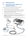
2.1 Getting started ......................................................................................................... 28
2.1.1 Connect the AC power adapter to your Embedded Computer .................. 28
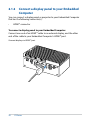
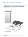
2.1.2 Connect a display panel to your Embedded Computer ................................ 30
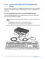
2.1.3 Connect the USB cable from keyboard or mouse ............................................ 31
2.1.4 Turn on your Embedded Computer ...................................................................... 32
2.2 Turning off your Embedded Computer...........................................................33
Chapter 3: Upgrading your Embedded Computer
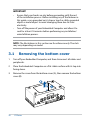
3.1 Removing the bottom cover ............................................................................... 36
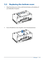
3.2 Replacing the bottom cover ...............................................................................37
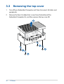
3.3 Removing the top cover .......................................................................................38
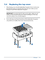
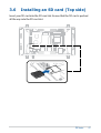
3.4 Replacing the top cover ........................................................................................39
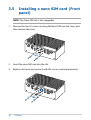
3.5 Installing a nano SIM card (Front panel) .........................................................40
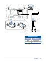
3.6 Installing an SD card (Top side) .......................................................................... 41
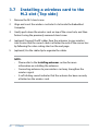
3.7 Installing a wireless card to the M.2 slot (Top side) ....................................42
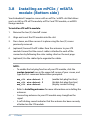
3.8 Installing an mPCIe / mSATA module (Bottom side) ..................................44
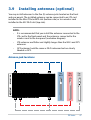
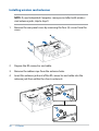
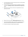
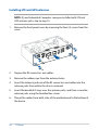
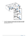
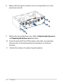
3.9 Installing antennas (optional) ............................................................................. 47
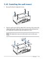
3.10 Installing the wall mount .....................................................................................53
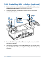
3.11 Installing DIN rail clips (optional) ......................................................................54
3.12 Installing the terminal block (optional) ...........................................................55

4
PE Series
Chapter 4: Setting up your Embedded Computer
4.1 Requirements ...........................................................................................................58
4.2 Flashing the OS Image ..........................................................................................58
Appendix
Safety information .............................................................................................................62
Setting up your system ............................................................................................................ 62
Care during use ........................................................................................................................... 63
Regulatory notices ............................................................................................................65
Service and Support .........................................................................................................78

PE Series
5
About this manual
This manual provides information about the hardware and software features
of your Embedded Computer, organized through the following chapters:
Chapter 1: Getting to know your Embedded Computer
This chapter details the hardware components of your Embedded
Computer.
Chapter 2: Using your Embedded Computer
This chapter provides you with information on using your Embedded
Computer.
Chapter 3: Upgrading your Embedded Computer
This chapter provides you with information on how to upgrade the
memory modules, wireless modules, and hard disk drive / solid state
drive of your Embedded Computer.
Chapter 4: Setting up your Embedded Computer
This chapter will guide you in setting up your Embedded Computer for
the first time.
Appendix
This section includes notices and safety statements your Embedded
Computer.

6
PE Series
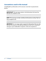
Conventions used in this manual
To highlight key information in this manual, some text are presented as
follows:
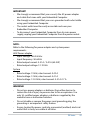
IMPORTANT! This message contains vital information that must be
followed to complete a task.
NOTE: This message contains additional information and tips that can
help complete tasks.
WARNING! This message contains important information that must be
followed to keep you safe while performing certain tasks and prevent
damage to your Embedded Computer's data and components.

PE Series
7
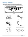
Package contents
Your Embedded Computer package contains the following items:
PE100A
AC power adapter* Power cord*
Terminal blocks Terminal block power adapter
I/O port dust covers Wall mount kit

8
PE Series
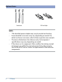
NOTE:
• *The bundled power adapter may vary by model and territory.
• Some bundled accessories may vary depending on model. For
details on these accessories, refer to their respective user manuals.
• The device illustration is for reference only. Actual product
specifications may vary depending on model.
• If the device or its components fail or malfunction during normal
and proper use within the warranty period, bring the warranty
card to the ASUS Service Center for replacement of the defective
components.
Optional items
Antennas DIN rail clips

1
Getting to know your
Embedded Computer

10
PE Series
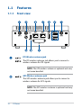
1.1 Features
1.1.1 Front view
LTE Wireless antenna jack
The LTE wireless antenna jack allows you to connect a
wireless antenna for LTE signals.
NOTE: The LTE wireless antenna is optional and may
not come bundled.
GPS Wireless antenna jack
The GPS wireless antenna jack allows you to connect a
wireless antenna for GPS signals.
NOTE: The GPS wireless antenna is optional and may
not come bundled.

PE Series
11
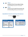
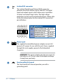
LAN port
The Realtek® RTL8211 Ethernet controllers with 8-pin
RJ-45 LAN port supports a standard Ethernet cable for
10/100/1000 Mbps connection to a local network.
LAN port
The Intel® I211/I210-AT Gigabit Ethernet controllers with
8-pin RJ-45 LAN port supports a standard Ethernet cable
for 10/100/1000 Mbps connection to a local network.
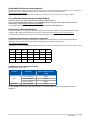
Activity Link LED
Status Description
Off No link
Yellow Linked
Yellow (blinking) Data activity
Yellow (blinking then
steady)
Ready to wake
up from suspend
mode
Speed LED
Status Description
Off 10 Mbps connection
Orange 100 Mbps connection
Green 1 Gbps connection
Realtek RTL8211 & Intel I211/I210 LAN port LED indications
ACT/LINK LED SPEED LED
LAN port

12
PE Series
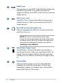
HDMI™ port
The integrated 19-pin HDMI™ (High Definition Multimedia
Interface) 2.0 port with a receptacle connector can
support resolutions up to 3840 x 2160 @ 60 Hz on external
display devices.
USB 3.2 Gen 1 port
The USB 3.2 Gen 1 (Universal Serial Bus) port provides a
transfer rate up to 5 Gbit/s and a maximum of 5V/0.9A
output per port.
Nano SIM card slot with metal cover
The hot-swappable nano SIM slot is located on the front
panel for easy access.
NOTE: This slot is covered with a metal cover.
Ensure to remove and replace the metal cover when
installing a nano SIM card. For more information on
removing and replacing the metal cover, refer to
Installing a nano SIM card.
USB 3.2 Gen 1 Type-C® port
This USB Type-C® (Universal Serial Bus) port provides a
transfer rate of up to 5 Gbit/s and a maximum of 5V/1.5A
output. This port supports OTG (On-The-Go) mode that
can allow to act as a device for flashing OS image via host
PC.
Power button
The power button allows you to turn the Embedded
Computer on or off with a single press. To force your
Embedded Computer to shutdown, press and hold the
power button for ten (10) seconds.

PE Series
13
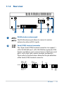
1.1.2 Rear view
WLAN wireless antenna jack
The WLAN antenna jack allows to connect a wireless
antenna to enhance Wi-Fi signals.
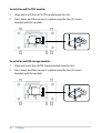
Serial (COM) terminal connector
The 10-pin Serial (COM) terminal connector can support 1
x RS-232/422/485 and 1 x RS-232/CAN Bus (optional) COM
headers and allows you to connect devices that have serial
ports, such as bar code scanner, modem, and printers.
Please refer to the illustrations below for the pin definition
of the Serial (COM) terminal connector.
12345
6 7 8 9 10
RS232
GND
RTS#
TX
RX
CTS#
GND
RTS#
CTS#
RX
TX
CAN
GND
CAN L
CAN H
RS422
GND
RB
RA
TA
TB
RS485
GND
A
B
12345
6 7 8 9 10
RS232
GND
RTS#
TX
RX
CTS#
GND
RTS#
CTS#
RX
TX
CAN
GND
CAN L
CAN H
RS422
GND
RB
RA
TA
TB
RS485
GND
A
B
12345
6 7 8 9 10
RS232
GND
RTS#
TX
RX
CTS#
GND
RTS#
CTS#
RX
TX
CAN
GND
CAN L
CAN H
RS422
GND
RB
RA
TA
TB
RS485
GND
A
B
12345
6 7 8 9 10
RS232
GND
RTS#
TX
RX
CTS#
GND
RTS#
CTS#
RX
TX
CAN
GND
CAN L
CAN H
RS422
GND
RB
RA
TA
TB
RS485
GND
A
B

14
PE Series
Isolated DIO connector
The Isolated Digital Input/Output (DIO) connector
provides electrical isolation (up to 2500 VDC) of digital
input and output signals, which allow micro controllers
to detect and output logic states. The high voltage
protection can be used in industrial level uses. Please refer
to the illustration below for the Isolated DIO connector’s
pin definitions.
DO4 L
DO4 H
DO3 L
DO3 H
DO2 L
DO2 H
DO1 L
DO1 H
DI4 L
DI4 H
DI3 L
DI3 H
DI2 L
DI2 H
DI1 L
DI1 H
Power input
The supplied terminal block power adapter converts AC
power to DC power for use with this jack. Power supplied
through this jack supplies power to the Embedded
Computer.
WARNING! The power adapter may become warm to
hot when in use. Do not cover the adapter and keep
it away from your body.
Functional Earth Ground
The Functional Earth Ground provides you with a
grounding point.
Signal Specifications
DO Output voltage range 0~24 VDC
Rated output current 1A
DI
Voltage for logic “0” 0~0.8 VDC
Voltage for logic “1” 5~24 VDC
Rated input current ±50 mA

PE Series
15
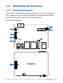
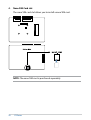
1.2 Motherboard Overview
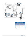
1.2.1 Motherboard layout
The PE100A is an Embedded Computer based on a Pico-ITX motherboard
and is supported by a secondary I/O board for extra functionality. Refer to
the table for the page numbers of the numbered items.
Pico-ITX motherboard

16
PE Series
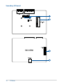
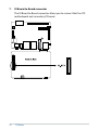
Secondary I/O board

PE Series
17
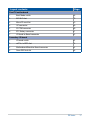
Layout contents Page
Pico-ITX motherboard
1. Boot Mode switch 18
2. M.2 Wi-Fi slot 19
3. Micro SD card slot 19
4. I2C connector 20
5. SPI TPM connector 20
6. RTC Battery connector 21
7. IO Board-to-Board connector 22
Secondary I/O board
1. IO board switch 23
2. mPCIe / mSATA slot 24
3. Motherboard Board-to-Board connector 25
4. Nano SIM Card slot 26

18
PE Series
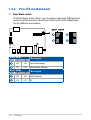
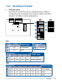
1.2.2 Pico-ITX motherboard
1. Boot Mode switch
The Boot Mode switch allows you to configure between different boot
modes and the location to boot from. Please refer to the table below
for the different boot modes.
Boot Mode Boot type
1 2
OFF ON Serial Downloader
ON OFF Internal Boot (default)
Boot Mode Boot type
3 4
OFF ON eMMC (default)
ON OFF SD

PE Series
19
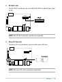
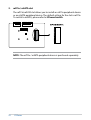
2. M.2 Wi-Fi slot
The M.2 Wi-Fi slot allows you to install an M.2 Wi-Fi module (E-key, type
2230).
NOTE: The M.2 Wi-Fi module is purchased separately.
3. Micro SD Card slot
The micro SD Card slot allows you to install a micro SD card.
NOTE: The micro SD card is purchased separately.

20
PE Series
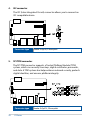
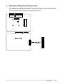
4. I2C connector
The I2C (Inter-Integrated Circuit) connector allows you to connect an
I2C compatible device.
Connector type
Header 2x3p, K6, 2.0mm pitch
5. SPI TPM connector
The SPI TPM connector supports a Trusted Platform Module (TPM)
system, which can securely store keys, digital certificates, passwords,
and data. A TPM system also helps enhance network security, protects
digital identities, and ensures platform integrity.
Connector type
Header 2x7p,K14, 2.0mm pitch
Pagina se încarcă...
Pagina se încarcă...
Pagina se încarcă...
Pagina se încarcă...
Pagina se încarcă...
Pagina se încarcă...
Pagina se încarcă...
Pagina se încarcă...
Pagina se încarcă...
Pagina se încarcă...
Pagina se încarcă...
Pagina se încarcă...
Pagina se încarcă...
Pagina se încarcă...
Pagina se încarcă...
Pagina se încarcă...
Pagina se încarcă...
Pagina se încarcă...
Pagina se încarcă...
Pagina se încarcă...
Pagina se încarcă...
Pagina se încarcă...
Pagina se încarcă...
Pagina se încarcă...
Pagina se încarcă...
Pagina se încarcă...
Pagina se încarcă...
Pagina se încarcă...
Pagina se încarcă...
Pagina se încarcă...
Pagina se încarcă...
Pagina se încarcă...
Pagina se încarcă...
Pagina se încarcă...
Pagina se încarcă...
Pagina se încarcă...
Pagina se încarcă...
Pagina se încarcă...
Pagina se încarcă...
Pagina se încarcă...
Pagina se încarcă...
Pagina se încarcă...
Pagina se încarcă...
Pagina se încarcă...
Pagina se încarcă...
Pagina se încarcă...
Pagina se încarcă...
Pagina se încarcă...
Pagina se încarcă...
Pagina se încarcă...
Pagina se încarcă...
Pagina se încarcă...
Pagina se încarcă...
Pagina se încarcă...
Pagina se încarcă...
Pagina se încarcă...
Pagina se încarcă...
Pagina se încarcă...
-
 1
1
-
 2
2
-
 3
3
-
 4
4
-
 5
5
-
 6
6
-
 7
7
-
 8
8
-
 9
9
-
 10
10
-
 11
11
-
 12
12
-
 13
13
-
 14
14
-
 15
15
-
 16
16
-
 17
17
-
 18
18
-
 19
19
-
 20
20
-
 21
21
-
 22
22
-
 23
23
-
 24
24
-
 25
25
-
 26
26
-
 27
27
-
 28
28
-
 29
29
-
 30
30
-
 31
31
-
 32
32
-
 33
33
-
 34
34
-
 35
35
-
 36
36
-
 37
37
-
 38
38
-
 39
39
-
 40
40
-
 41
41
-
 42
42
-
 43
43
-
 44
44
-
 45
45
-
 46
46
-
 47
47
-
 48
48
-
 49
49
-
 50
50
-
 51
51
-
 52
52
-
 53
53
-
 54
54
-
 55
55
-
 56
56
-
 57
57
-
 58
58
-
 59
59
-
 60
60
-
 61
61
-
 62
62
-
 63
63
-
 64
64
-
 65
65
-
 66
66
-
 67
67
-
 68
68
-
 69
69
-
 70
70
-
 71
71
-
 72
72
-
 73
73
-
 74
74
-
 75
75
-
 76
76
-
 77
77
-
 78
78


în alte limbi
- English: Asus PE100A User manual
Lucrări înrudite
-
Asus E1600WK Manualul utilizatorului
-
Asus PE1100N Manual de utilizare
-
-
-
-
Asus H170I-PRO Manual de utilizare
-
Asus ROG STRIX B760-G GAMING WIFI Manual de utilizare
-
-
Asus ProArt B760-CREATOR Manual de utilizare
-
Alte documente
-
Edimax DWA-T185 11ac 2T2R Wireless LAN USB Adapter Ghid de instalare
-
Edimax EW-7822UAC Ghid de instalare
-
Hikvision DS-2XS6F45G1-IC1(/C2)/4G Ghid de inițiere rapidă
-
Calix GigaSpire Instrucțiuni de utilizare
-
 Ava RM-RX1 Instrucțiuni de utilizare
-
VISTEON SLA8 Manual de utilizare
-
Lenovo Wireless LAN/WAN Modules Manual de utilizare
-
Furuno GP-320B Manualul proprietarului
-
Forever KW-510 Manualul utilizatorului
