Ferm HDM1024 Manual de utilizare
- Categorie
- Unelte electrice
- Tip
- Manual de utilizare

EN
Original instructions
03
Art.no. HDM1024
ROTORY HAMMER DRILL
EBH-850KN
1102-24

2
9
11
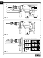
Front switch lever Back switch lever
D1
D2
D3
2
3
4
6
10
11
8
7
9
1
12
5
Fig. C Fig. D
Fig. B
Fig. A
FIG.

EN
3
ROTARY HAMMER DRILL
Thank you for buying this Ferm product.
By doing so you now have an excellent product,
delivered by one of European leading suppliers.
All products delivered to you by Ferm are
manufactured according to the highest standards
of performance and safety. As part of our
philosophy we also provide an excellent customer
service, backed by our comprehensive Warranty.
We hope you will enjoy using this product for
many years to come.
The numbers in the following text correspond
with the pictures at page 2.
Read this manual carefully, before using the
machine. Ensure that you know how the
machine works, and how it should be
operated. Maintain the machine in
accordance with the instructions, and make
certain that the machine functions correctly.
Store this manual and other enclosed
documentation with the machine.
Intended use
The EBH-850KN is intended for drilling holes
in masonry such as brick, concrete and similar
materials. Furthermore, the machine can be used
as a demolition hammer in combination with the
SDS cold chisels provided. The machine is on no
account intended for other purposes.
Not suitable for construction site usage.
Please inspect the machine and accessories for
transit damage.
Contents
1. Machine information
2. Safety instructions
3. Operating
4. Maintenance
1. Machine information
Technical specifications
Voltage 230 V
Frequency 50 Hz
Power rating 850 W
Rotational speed, not loaded 800/min
Impact rate 4000/min
Max. bit diameter
Concrete Ø 26 mm
Steel Ø 13 mm
Wood Ø 40 mm
Weight 4.5 kg
Lpa 83.6+3 dB(A)
Lwa 94.6+3 dB(A)
Vibration
When chiseling 17.46+1.5 m/s
2
When hammering in concrete 20.23+1.5 m/s
2
Product information
Fig. A+D
1. Rotary stop selection lever
2. On-off Switch
3. Main handle
4. Hammer stop selection lever
5. Carbon brush cap
6. Electric cord
7. Auxiliary handle
8. Depth gauge
9. Dust cap
10. Drill
11. Locking sleeve
12 Grease cap
2. Safety instructions
Explanation of the symbols
Denotes risk of personal injury, loss of life
or damage to the tool in case of non-
observance of the instructions in this
manual.
Indicates electrical shock hazard.
Wear ear and eye protection
Wear a dust mask. Working with wood,
metals and other materials may produce
dust that is harmful to health. Do not work
with material containing asbestos
Specific safety instructions
For use of this machine/tool:
Inspect the surface to be drilled for hidden •
electrical wiring, gas pipes or other obstacles
(for example, using a metal detector).
Check the following points:•
Does the appliance’s voltage correspond •

EN
4
with the mains power supply voltage?
Are power cords, insulation and plug in •
good order: sound, not loose or
damaged?
Is there a good, firm connection at the •
mains socket?
Does the drill show any sign of abnormal •
running, overheating or excessive
sparking?
Whenever any of the problems mentioned •
above appear, immediately cease using
the machine and have it repaired by an
expert.
Wear ear protectors. Exposure to noise can •
cause hearing loss.
Use auxiliary handles supplied with the tool. •
Loss of control can cause personal injury.
Hold power tool by insulated gripping surfaces,
when performing an operation where the cutting
accessory may contact hidden wiring or its own
cord. Cutting accessory contacting a “live” wire
may make exposed metal parts of the power tool
“live” and give the operator an electric shock.
Electrical safety
When using electric machines always observe the
safety regulations applicable in your country to
reduce the risk of fire, electric shock and personal
injury. Read the following safety instructions and
also the enclosed safety instructions.
Always check that the mains voltage is
the same as on the type plate of the
machine.
Class II machine – Double insulation –
You don’t need any earthed plug.
Replacement of power cords or plugs
Immediately dispose of old cords and plugs once
they have been replaced. It is dangerous to plug a
loose power cord into a mains power socket.
Use of extension leads
Only ever use approved extension leads that are
suitable for the power rating of the machine. The
mini mum core thickness is 1.5 mm
2
. Whenever
using a reel extension lead, always fully unroll the
lead.
Immediately switch off the machine when:
Excessive sparking of the carbon brushes and •
verticiliosis in the collector.
Interruption of the mains plug, mains lead or •
mains lead damage.
Defect switch•
Smoke or stench of scorched isolation•
3. Operating
Hammer drills require very little operator
pressure. Excessive pressure on the tool
can lead to unnecessary overheating of
the motor, and burning of the driven tool.
Auxiliary handgrip
The auxiliary handgrip can be rotated 360º around
the drill head, enabling safe and comfortable
operation, for both left and right-handed users:
Loosen the handgrip by turning it •
anticlockwise.
Rotate the handgrip to the desire position.•
Retighten the handgrip in the new position.•
Exchanging and removing drill bits
Fig. A+B
Before exchanging bits, first remove the
power plug from the wall socket.
Inspect bits regularly during use. Blunt
bits should be re-sharpened or replaced.
Lightly oil the bit shaft before inserting it into •
the chuck.
Slide the locking sleeve (11) to the rear, and •
insert the bit into the chuck opening. Ensure
that the keyway in the bit is seated properly in
the chuck, by carefully turning the bit until it
clicks into place. Release the locking sleeve.
To remove the bit, slide and hold the locking •
sleeve to the rear.
Setting depth gauge
Loosen the handgrip by turning it anticlockwise.•
Insert the depth gauge ruler through the hole •
in the auxiliary handgrip.
Slide the ruler to the desired depth.•
Retighten the screw firmly.•
Function selection switch
Fig. D
The correct position of the selection switch for

EN
5
each machine function is given in the diagram
(Fig.C) on page 2.
1 = Demolition hammer/chisel
2 = Rotary hammer drill
3 = Drilling
Switching On/Off
To start the drill, squeeze the trigger.•
To stop the drill, release the trigger.•
Installing dust catcher
Fig. C
The dust catcher prevents large amounts of
drilling dust entering the machine when drilling
into ceilings:
Remove the drill bit.•
Slide the dust catcher over the shaft of the drill •
bit.
Place the drill bit with catcher in the drill •
chuck.
Always replace a damaged dust catcher •
immediately.
4. Maintenance
Take care that the machine is not
connected to power whenever
maintenance work on the mechanical
parts is taking place.
The machines are designed to function
problem-free for a long period with a minimum
of maintenance. Through regular cleaning and
correct treatment, you help assure a long working
life for your machine.
Defects
The machine should be regularly inspected for
the following possible defects, and repaired if
necessary.
Damage to power cord•
Broken on/off trigger assembly.•
Short circuiting.•
Damaged moving parts.•
Trouble shooting
1. When switched on, the motor does not
turn.
Failure in power supply.•
Check the power supply.•
Poor contact in the on/off trigger.•
Repair or replace the trigger assembly.•
Mains voltage too low.•
Extension lead too long, or too light.•
Damaged motor.•
Have your machine repaired by an expert.•
Carbon brushes worn.•
Replace the carbon brushes•
2. Motor generates excessive noise, and
runs too slowly or not at all.
Motor is overloaded due to excessive •
pressure or drilling depth.
Reduce the pressure or drilling depth, •
reduce power.
Damaged motor.•
Have your machine repaired by an expert.•
Supply voltage too low.•
Adjust the supply voltage.•
Carbon brushes worn.•
Replace the carbon brushes•
3. Overheating in the transmission case.
Overloading of machine, or blunt drill bit•
Reduce the loading, or hone the drill bit.•
Reduced voltage.•
Adjust the supply voltage.•
4. Heavy sparking from the motor.
Inspect the carbon brushes for wear.•
Replacing carbon brushes
Replace both carbon brushes at the same •
time.
Regularly check the carbon brushes for wear •
and defects.
Always replace worn-out carbon brushes.•
Always keep the carbon brushes clean, and •
make sure that neither brush is obstructed.
Open the machine to inspect/replace the •
carbon brushes.
Remove and replace the carbon brushes if •
necessary.
Reassemble the rear handgrip.•
Cleaning
Clean the machine casings regularly with a soft
cloth, preferably after each use. Make sure that
the ventilation openings are free of dust and
dirt. Remove very persistent dirt using a soft
cloth moistened with soapsuds. Do not use any
solvents such as gasoline, alcohol, ammonia,
etc. Chemicals such as these will damage the
synthetic components.

EN
6
Lubrication
Regularly grease the hammer drill shaft. •
Regularly check the grease-level inside the •
machine:
Remove the grease cap (12) on top of the •
machine.
Remove also the second cap (with 4 •
notches)
Now you can see the rotating parts inside •
the machine: there should be grease on
the moving parts.
If necessary put some grease into the •
hole.
Place the cap onto the hole and tighten it •
again.
Mount the grease cap again.•
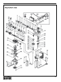
Faults
Should a fault occur, e.g. after wear of a part,
please contact the service address on the
warranty card. In the back of this manual you find
an exploded view showing the parts that can be
ordered.
Environment
To prevent damage during transport, the
appliance is delivered in a solid packaging which
consists largely of reusable material. Therefore
please make use of options for recycling the
packaging.
Faulty and/or discarded electrical or
electronic apparatus have to be collected
at the appropriate recycling locations.
Warranty
For the conditions of warranty, please refer to the
separately provided warranty card.
The product and the user manual are subject to
change. Specifications can be changed without
further notice.

7

8

9
DECLARATION OF CONFORMITY
EBF-850KN ROTARY HAMMER
(GB) We declare under our sole responsibility that this product
is in conformity and accordance with the following
standards and regulations:
(DE) Der Hersteller erklärt eigenverantwortlich, dass dieses
Produkt den folgenden Standards und Vorschriften
entspricht:
(NL) Wij verklaren onder onze volledige verantwoordelijk heid
dat dit product voldoet aan, en in overeenstem ming is
met, de volgende standaarden en reguleringen:
(FR) Nous déclarons sous notre seule responsabilité que ce
produit est conforme aux standards et directives
suivants:
(ES) Declaramos bajo nuestra exclusiva responsabilidad que
este producto cumple con las siguientes normas y
estándares de funcionamiento:
(PT) Declaramos por nossa total responsabilida-de que este
produto está em conformidade e cumpre as normas e
regulamentações que se seguem:
(IT) Dichiariamo, sotto la nostra responsabilità, che questo
prodotto è conforme alle normative e ai regolamenti
seguenti:
(SV) Vi garanterar på eget ansvar att denna produkt upp fyller
och följer följande standarder och bestämmelser:
(FI) Vakuutamme yksinomaan omalla vastuullamme, että
tämä tuote täyttää seuraavat standardit ja säädökset:
(NO) Vi erklærer under vårt eget ansvar at dette produktet er i
samsvar med følgende standarder og regler:
(DA) Vi erklærer under eget ansvar, at dette produkt er i
overensstemmelse med følgende standarder og
bestemmelser:
(HU) Felelősségünkteljestudatábankijelentjük,hogyeza
termék teljes mértékben megfelel az alábbi
szabványoknakéselőírásoknak:
(CS) Nanašivlastnízodpovědnostprohlašujeme,žejetento
výrobekvsouladusnásledujícímistandardyanormami:
(SK) Vyhlasujemenanašuvýhradnúzodpovednosť,žetento
výrobok je v zhode a súlade s nasledujúcimi normami a
predpismi:
(SL) S polno odgovornostjo izjavljamo, da je ta izdelek v skla-
du in da odgovarja naslednjim standardom terpredpisom:
(PL) Deklarujemynawłasnąodpowiedzialność,żetenprodukt
spełniawymogizawartewnastępującychnormachi
przepisach:
(LT) Prisiimdamivisąatsakomybędeklaruojame,kadšis
gaminysatitinkažemiaupaminėtusstandartusarba
nuostatus:
(LV) Apgalvojamarvisuatbildību,kašisproduktsirsaskaņā
un atbilst sekojošiem standartiem un nolikumiem:
(ET) Deklareerime meie ainuvastutusel, et see toode on vasta-
vuses ja kooskõlas järgmiste standardite ja määrustega:
(RO) Declarămprinaceastacurăspundereadeplinăcă
produsulacestaesteînconformitatecuurmătoarele
standarde sau directive:
(HR) IzjavljujemopodvlastitomodgovornoĻśudajestrojem
ukladansaslijedeśimstandardimailistandardiziranim
dokumentima i u skladu sa odredbama:
(SR) Podpunomodgovornošćuizjavljujemodajeusaglašen
sasledećimstandardimailinormama:
(RU) Подсвоюответственностьзаявляем,чтоданное
изделиесоответствуетследующимстандартами
нормам:
(UK) Насвоювласнувідповідальністьзаявляємо,щодане
обладнаннявідповідаєнаступнимстандартамі
нормативам:
(EL) Δηλώνουμευπεύθυναότιπροϊόναυτόσυμφωνείκαιτηρεί
τουςπαρακάτωκανονισμούςκαιπρότυπα:
(BG) Ниезаявяваме,посвоясобственаотговорност,че
тозипродукт
отговарянаследнитестандартии
директиви
EN60745-1, EN60745-2-6, EN55014-1, EN55014-2, EN61000-3-2,
EN61000-3-3
2006/42/EC, 2006/95/EC, 2000/14/EC, 2004/108/EC, 2002/96/EC, 2002/95/EC
Zwolle, 01-02-2011
I. Mönnink
CEO Ferm BV
It is our policy to continuously improve our products and we therefore reserve the right to change the
product specification without prior notice.
Ferm BV • Lingenstraat 6 • 8028 PM • Zwolle The Netherlands

10
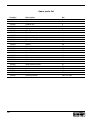
Spare parts list
Position Description No.
102880 Steel ball 2
102881 Cylinder 3
102882 Feather key 4
102883 Piston 5
102884 O-ring 6
102885 Third gear 7
102886 Piston 8
102887 Connecting shaft 10
102888 Needle bearing 11
102904 Front selection lever 15
102889 Front cover 27
102890 Sleeve 29
102891 Second hammer 34
102892 Pinion gear 38
102893 Special nut 45
102894 Crank shaft 48
102896 Rotor 58
102898 Carbon brush holder 63
102899 Carbon brush set 64
102900 Carbon brush cap 65
102905 Rear selection lever 67
102897 Stator 69
102901 Switch 77
102902 Dust cover 501
102903 Depth limiter 504
102895 Auxiliary handle 505 TILL 509

11
Exploded view

www.ferm.com
-
 1
1
-
 2
2
-
 3
3
-
 4
4
-
 5
5
-
 6
6
-
 7
7
-
 8
8
-
 9
9
-
 10
10
-
 11
11
-
 12
12


Ferm HDM1024 Manual de utilizare
- Categorie
- Unelte electrice
- Tip
- Manual de utilizare
în alte limbi
- English: Ferm HDM1024 User manual
- dansk: Ferm HDM1024 Brugermanual
Lucrări înrudite
Alte documente
-
Tryton TMM1050K Manual de utilizare
-
-
Parkside PBH 1100 A1 Operation and Safety Notes
-
Ryobi EID750RS Manual de utilizare
-
Hikoki DH22PG Manual de utilizare
-
Parkside PBH 1050 A1 Operation and Safety Notes
-
Bavaria BRH 1208 E Instrucțiuni de utilizare
-
RIDGID 535M Manual de utilizare