
www.mellanox.com
SwitchX 36-Port QSFP InfiniBand- Ethernet
Gateway System Hardware User Manual
P/N: MSX6036G-2SFS, MSX6036G-2SRS
Rev 1.0

Document Number: MLNX-15-937
Rev 1.0
Mellanox Technologies
2
Mellanox Technologies
350 Oakmead Parkway Suite 100
Sunnyvale, CA 94085
U.S.A.
www.mellanox.com
Tel: (408) 970-3400
Fax: (408) 970-3403
Mellanox Technologies, Ltd.
Beit Mellanox
PO Box 586 Yokneam 20692
Israel
www.mellanox.com
Tel: +972 (0)74 723 7200
Fax: +972 (0)4 959 3245
© Copyright 2013. Mellanox Technologies. All Rights Reserved.
Mellanox®, Mellanox logo, BridgeX®, ConnectX®, CORE-Direct®, InfiniBridge®, InfiniHost®, InfiniScale®,
MLNX-OS®, PhyX®, SwitchX®, UFM®, Virtual Protocol Interconnect® and Voltaire® are registered trademarks of
Mellanox Technologies, Ltd.
Connect-IB™, ExtendX™, FabricIT™, Mellanox Open Ethernet™, Mellanox Virtual Modular Switch™, MetroX™,
MetroDX™, ScalableHPC™, Unbreakable-Link™ are trademarks of Mellanox Technologies, Ltd.
All other trademarks are property of their respective owners.
NOTE:
THIS HARDWARE, SOFTWARE OR TEST SUITE PRODUCT (“PRODUCT(S)”) AND ITS RELATED
DOCUMENTATION ARE PROVIDED BY MELLANOX TECHNOLOGIES “AS-IS” WITH ALL FAULTS OF ANY
KIND AND SOLELY FOR THE PURPOSE OF AIDING THE CUSTOMER IN TESTING APPLICATIONS THAT USE
THE PRODUCTS IN DESIGNATED SOLUTIONS. THE CUSTOMER'S MANUFACTURING TEST ENVIRONMENT
HAS NOT MET THE STANDARDS SET BY MELLANOX TECHNOLOGIES TO FULLY QUALIFY THE
PRODUCTO(S) AND/OR THE SYSTEM USING IT. THEREFORE, MELLANOX TECHNOLOGIES CANNOT AND
DOES NOT GUARANTEE OR WARRANT THAT THE PRODUCTS WILL OPERATE WITH THE HIGHEST
QUALITY. ANY EXPRESS OR IMPLIED WARRANTIES, INCLUDING, BUT NOT LIMITED TO, THE IMPLIED
WARRANTIES OF MERCHANTABILITY, FITNESS FOR A PARTICULAR PURPOSE AND NONINFRINGEMENT
ARE DISCLAIMED. IN NO EVENT SHALL MELLANOX BE LIABLE TO CUSTOMER OR ANY THIRD PARTIES
FOR ANY DIRECT, INDIRECT, SPECIAL, EXEMPLARY, OR CONSEQUENTIAL DAMAGES OF ANY KIND
(INCLUDING, BUT NOT LIMITED TO, PAYMENT FOR PROCUREMENT OF SUBSTITUTE GOODS OR SERVICES;
LOSS OF USE, DATA, OR PROFITS; OR BUSINESS INTERRUPTION) HOWEVER CAUSED AND ON ANY
THEORY OF LIABILITY, WHETHER IN CONTRACT, STRICT LIABILITY, OR TORT (INCLUDING NEGLIGENCE
OR OTHERWISE) ARISING IN ANY WAY FROM THE USE OF THE PRODUCT(S) AND RELATED
DOCUMENTATION EVEN IF ADVISED OF THE POSSIBILITY OF SUCH DAMAGE.

SwitchX 36-Port QSFP InfiniBand- Ethernet Gateway System Hardware User Manual Rev 1.0
Mellanox Technologies
3
Table of Contents
Table of Contents . . . . . . . . . . . . . . . . . . . . . . . . . . . . . . . . . . . . . . . . . . . . . . . . . . . . . . . . . . 3
List of Figures . . . . . . . . . . . . . . . . . . . . . . . . . . . . . . . . . . . . . . . . . . . . . . . . . . . . . . . . . . . . . 5
List of Tables . . . . . . . . . . . . . . . . . . . . . . . . . . . . . . . . . . . . . . . . . . . . . . . . . . . . . . . . . . . . . 7
Revision History . . . . . . . . . . . . . . . . . . . . . . . . . . . . . . . . . . . . . . . . . . . . . . . . . . . . . . . . . . . 8
About this Manual . . . . . . . . . . . . . . . . . . . . . . . . . . . . . . . . . . . . . . . . . . . . . . . . . . . . . . . . . 9
Intended Audience . . . . . . . . . . . . . . . . . . . . . . . . . . . . . . . . . . . . . . . . . . . . . . . . . . . . . .9
Related Documentation . . . . . . . . . . . . . . . . . . . . . . . . . . . . . . . . . . . . . . . . . . . . . . . . . .9
Conventions . . . . . . . . . . . . . . . . . . . . . . . . . . . . . . . . . . . . . . . . . . . . . . . . . . . . . . . . . . .9
Abbreviations . . . . . . . . . . . . . . . . . . . . . . . . . . . . . . . . . . . . . . . . . . . . . . . . . . . . . . . . .10
Mellanox Part Numbering Legend . . . . . . . . . . . . . . . . . . . . . . . . . . . . . . . . . . . . . . . . .10
Chapter 1 Overview. . . . . . . . . . . . . . . . . . . . . . . . . . . . . . . . . . . . . . . . . . . . . . . . . . . . . . 11
1.1 Features . . . . . . . . . . . . . . . . . . . . . . . . . . . . . . . . . . . . . . . . . . . . . . . . . . . . . . . . 12
1.2 Serial Number and Product Version Information . . . . . . . . . . . . . . . . . . . . . . . . 14
1.3 Ethernet Ports. . . . . . . . . . . . . . . . . . . . . . . . . . . . . . . . . . . . . . . . . . . . . . . . . . . . 14
1.4 FDR Transmission Rate. . . . . . . . . . . . . . . . . . . . . . . . . . . . . . . . . . . . . . . . . . . . 14
Chapter 2 Basic Operation . . . . . . . . . . . . . . . . . . . . . . . . . . . . . . . . . . . . . . . . . . . . . . . . 16
2.1 Gateway Platform Hardware Overview. . . . . . . . . . . . . . . . . . . . . . . . . . . . . . . . 16
2.2 Status LEDs . . . . . . . . . . . . . . . . . . . . . . . . . . . . . . . . . . . . . . . . . . . . . . . . . . . . . 16
2.2.1 System Status LEDs . . . . . . . . . . . . . . . . . . . . . . . . . . . . . . . . . . . . . . . . . . . . . . . 17
2.2.2 Gateway Status LED. . . . . . . . . . . . . . . . . . . . . . . . . . . . . . . . . . . . . . . . . . . . . . . 18
2.2.3 Fan Status LED . . . . . . . . . . . . . . . . . . . . . . . . . . . . . . . . . . . . . . . . . . . . . . . . . . . 19
2.2.4 Power Supply Status LEDs . . . . . . . . . . . . . . . . . . . . . . . . . . . . . . . . . . . . . . . . . . 20
2.2.5 Bad Port LED . . . . . . . . . . . . . . . . . . . . . . . . . . . . . . . . . . . . . . . . . . . . . . . . . . . . 22
2.2.6 UID LED Gateway Identifier . . . . . . . . . . . . . . . . . . . . . . . . . . . . . . . . . . . . . . . . 22
2.3 Port Connector LEDs. . . . . . . . . . . . . . . . . . . . . . . . . . . . . . . . . . . . . . . . . . . . . . 23
2.4 Air Flow. . . . . . . . . . . . . . . . . . . . . . . . . . . . . . . . . . . . . . . . . . . . . . . . . . . . . . . . 24
2.5 QSFP Cable Power Budget Classification. . . . . . . . . . . . . . . . . . . . . . . . . . . . . . 26
2.6 Interfaces . . . . . . . . . . . . . . . . . . . . . . . . . . . . . . . . . . . . . . . . . . . . . . . . . . . . . . . 26
2.6.1 RJ-45 Connector “CONSOLE”. . . . . . . . . . . . . . . . . . . . . . . . . . . . . . . . . . . . . . . 27
2.6.2 USB Connector . . . . . . . . . . . . . . . . . . . . . . . . . . . . . . . . . . . . . . . . . . . . . . . . . . 27
2.6.3 I2C Connector . . . . . . . . . . . . . . . . . . . . . . . . . . . . . . . . . . . . . . . . . . . . . . . . . . . 28
2.6.4 Reset Button . . . . . . . . . . . . . . . . . . . . . . . . . . . . . . . . . . . . . . . . . . . . . . . . . . . . . 28
2.6.5 Port Connector Interfaces . . . . . . . . . . . . . . . . . . . . . . . . . . . . . . . . . . . . . . . . . . . 28
2.6.6 Port Protocol Configuration . . . . . . . . . . . . . . . . . . . . . . . . . . . . . . . . . . . . . . . . . 29
2.6.7 Port Speed Configuration . . . . . . . . . . . . . . . . . . . . . . . . . . . . . . . . . . . . . . . . . . . 29
Chapter 3 Installation . . . . . . . . . . . . . . . . . . . . . . . . . . . . . . . . . . . . . . . . . . . . . . . . . . . . 30
3.1 Installation Safety Warnings . . . . . . . . . . . . . . . . . . . . . . . . . . . . . . . . . . . . . . . . 30
3.1.1 Battery Replacement . . . . . . . . . . . . . . . . . . . . . . . . . . . . . . . . . . . . . . . . . . . . . . . 34
3.2 Package Contents. . . . . . . . . . . . . . . . . . . . . . . . . . . . . . . . . . . . . . . . . . . . . . . . . 34
3.3 Mechanical Installation . . . . . . . . . . . . . . . . . . . . . . . . . . . . . . . . . . . . . . . . . . . . 35
3.4 Grounding the Gateway. . . . . . . . . . . . . . . . . . . . . . . . . . . . . . . . . . . . . . . . . . . . 39

Rev 1.0
Mellanox Technologies
4
3.5 Power Connections and Initial Power On . . . . . . . . . . . . . . . . . . . . . . . . . . . . . . 40
3.6 Extracting and Inserting FRUs . . . . . . . . . . . . . . . . . . . . . . . . . . . . . . . . . . . . . . 41
3.6.1 Extracting and Inserting the Power Supply Unit. . . . . . . . . . . . . . . . . . . . . . . . . . 41
3.6.2 Extracting and Inserting the Fan Units . . . . . . . . . . . . . . . . . . . . . . . . . . . . . . . . . 42
3.7 Configuration. . . . . . . . . . . . . . . . . . . . . . . . . . . . . . . . . . . . . . . . . . . . . . . . . . . . 44
3.7.1 Configuring the Gateway for the First Time. . . . . . . . . . . . . . . . . . . . . . . . . . . . . 44
3.7.2 Starting a Remote connection and opening a Command Line (CLI) . . . . . . . . . . 49
Chapter 4 Cabling . . . . . . . . . . . . . . . . . . . . . . . . . . . . . . . . . . . . . . . . . . . . . . . . . . . . . . . 51
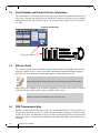
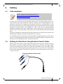
4.1 Cable Installation. . . . . . . . . . . . . . . . . . . . . . . . . . . . . . . . . . . . . . . . . . . . . . . . . 51
4.2 Splitting the Data Stream Using Breakout (Fanout) Cables . . . . . . . . . . . . . . . . 51
Chapter 5 Gateway Management. . . . . . . . . . . . . . . . . . . . . . . . . . . . . . . . . . . . . . . . . . . 56
5.1 Upgrading Software. . . . . . . . . . . . . . . . . . . . . . . . . . . . . . . . . . . . . . . . . . . . . . . 56
Chapter 6 Troubleshooting . . . . . . . . . . . . . . . . . . . . . . . . . . . . . . . . . . . . . . . . . . . . . . . . 57
Appendix A Specification . . . . . . . . . . . . . . . . . . . . . . . . . . . . . . . . . . . . . . . . . . . . . . . . . 59
A.1 Approved Cables . . . . . . . . . . . . . . . . . . . . . . . . . . . . . . . . . . . . . . . . . . . . . . 60
A.2 EMC Certifications. . . . . . . . . . . . . . . . . . . . . . . . . . . . . . . . . . . . . . . . . . . . . 60
A.3 China CCC Warning Statement . . . . . . . . . . . . . . . . . . . . . . . . . . . . . . . . . . . 61
Appendix B Thermal Threshold Definitions . . . . . . . . . . . . . . . . . . . . . . . . . . . . . . . . . 62
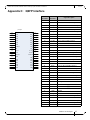
Appendix C QSFP Interface . . . . . . . . . . . . . . . . . . . . . . . . . . . . . . . . . . . . . . . . . . . . . . . 63
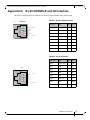
Appendix D RJ-45 CONSOLE and I2C Interface . . . . . . . . . . . . . . . . . . . . . . . . . . . . . 65
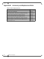
Appendix E Accessory and Replacement Parts . . . . . . . . . . . . . . . . . . . . . . . . . . . . . . . 66
Appendix F Disassembly of the Switch from the Rack . . . . . . . . . . . . . . . . . . . . . . . . . 67
F.1 Disposal . . . . . . . . . . . . . . . . . . . . . . . . . . . . . . . . . . . . . . . . . . . . . . . . . . . . . 67
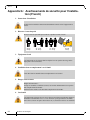
Appendix G Avertissements de sécurité pour l'installation (French) . . . . . . . . . . . . . . 68
Appendix H Installation – Sicherheitshinweise(German) . . . . . . . . . . . . . . . . . . . . . . . 73
Appendix I Advertencias de seguridad de instalación(Spanish) . . . . . . . . . . . . . . . . . 77
Appendix J Предупреждения по технике безопасности при установке(Russian) 82
Appendix K Avertismente privind siguranţa la instalare (Romanian) . . . . . . . . . . . . 87
Appendix L 安裝安全性警告 (Chinese) . . . . . . . . . . . . . . . . . . . . . . . . . . . . . . . . . . . . . 92

SwitchX 36-Port QSFP InfiniBand- Ethernet Gateway System Hardware User Manual Rev 1.0
Mellanox Technologies
5
List of Figures
Figure 1: Connector Side View of the Gateway . . . . . . . . . . . . . . . . . . . . . . . . . . . . . . . . . . . . . .11
Figure 2: Pull Out Tab . . . . . . . . . . . . . . . . . . . . . . . . . . . . . . . . . . . . . . . . . . . . . . . . . . . . . . . . . . .14
Figure 3: Gateway System Power and Connector Side Panels . . . . . . . . . . . . . . . . . . . . . . . . . .16
Figure 4: System Status LEDs . . . . . . . . . . . . . . . . . . . . . . . . . . . . . . . . . . . . . . . . . . . . . . . . . . . . .17
Figure 5: Gateway Status LEDs Front and Back . . . . . . . . . . . . . . . . . . . . . . . . . . . . . . . . . . . . . . .17
Figure 6: Gateway Status LED . . . . . . . . . . . . . . . . . . . . . . . . . . . . . . . . . . . . . . . . . . . . . . . . . . . .18
Figure 7: Fan Status LED Connector Side . . . . . . . . . . . . . . . . . . . . . . . . . . . . . . . . . . . . . . . . . . . .19
Figure 8: Fan Status LED Power Side . . . . . . . . . . . . . . . . . . . . . . . . . . . . . . . . . . . . . . . . . . . . . .20
Figure 9: Power Status LED Connector Side . . . . . . . . . . . . . . . . . . . . . . . . . . . . . . . . . . . . . . . . . .20
Figure 10: Power Side Panel . . . . . . . . . . . . . . . . . . . . . . . . . . . . . . . . . . . . . . . . . . . . . . . . . . . . . . .21
Figure 11: PS Unit Status LEDs . . . . . . . . . . . . . . . . . . . . . . . . . . . . . . . . . . . . . . . . . . . . . . . . . . . .21
Figure 12: Bad Port LED . . . . . . . . . . . . . . . . . . . . . . . . . . . . . . . . . . . . . . . . . . . . . . . . . . . . . . . . . .22
Figure 13: Identifier LED . . . . . . . . . . . . . . . . . . . . . . . . . . . . . . . . . . . . . . . . . . . . . . . . . . . . . . . . .23
Figure 14: Port LEDs . . . . . . . . . . . . . . . . . . . . . . . . . . . . . . . . . . . . . . . . . . . . . . . . . . . . . . . . . . . . .23
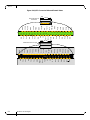
Figure 15: Component Air Flow . . . . . . . . . . . . . . . . . . . . . . . . . . . . . . . . . . . . . . . . . . . . . . . . . . . .25
Figure 16: Component Airflow Mismatch (Wrong) . . . . . . . . . . . . . . . . . . . . . . . . . . . . . . . . . . . . .25
Figure 17: Management Interfaces . . . . . . . . . . . . . . . . . . . . . . . . . . . . . . . . . . . . . . . . . . . . . . . . . . .27
Figure 18: Reset Button . . . . . . . . . . . . . . . . . . . . . . . . . . . . . . . . . . . . . . . . . . . . . . . . . . . . . . . . . .28
Figure 19: Port Numbering . . . . . . . . . . . . . . . . . . . . . . . . . . . . . . . . . . . . . . . . . . . . . . . . . . . . . . . .29
Figure 20: Top and Bottom QSFP Port Orientation . . . . . . . . . . . . . . . . . . . . . . . . . . . . . . . . . . . . .29
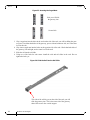
Figure 21: Rack Rail Kit Parts . . . . . . . . . . . . . . . . . . . . . . . . . . . . . . . . . . . . . . . . . . . . . . . . . . . . . .35
Figure 22: Placement of Gateway in Rack . . . . . . . . . . . . . . . . . . . . . . . . . . . . . . . . . . . . . . . . . . . . .36
Figure 23: Mounting Options . . . . . . . . . . . . . . . . . . . . . . . . . . . . . . . . . . . . . . . . . . . . . . . . . . . . . .37
Figure 24: Screwing on the Rail . . . . . . . . . . . . . . . . . . . . . . . . . . . . . . . . . . . . . . . . . . . . . . . . . . . . .37
Figure 25: Inserting the Caged Nuts . . . . . . . . . . . . . . . . . . . . . . . . . . . . . . . . . . . . . . . . . . . . . . . . .38
Figure 26: Slide the Rail into the Rail Slide . . . . . . . . . . . . . . . . . . . . . . . . . . . . . . . . . . . . . . . . . . .38
Figure 27: Status LEDs 5 Minutes After Power On . . . . . . . . . . . . . . . . . . . . . . . . . . . . . . . . . . . . .39
Figure 28: Two Power Inlets - Electric Caution Notifications . . . . . . . . . . . . . . . . . . . . . . . . . . . . .40
Figure 29: Fan and PS unit Air Flow Direction . . . . . . . . . . . . . . . . . . . . . . . . . . . . . . . . . . . . . . . . .41
Figure 30: Power Supply Unit Extraction . . . . . . . . . . . . . . . . . . . . . . . . . . . . . . . . . . . . . . . . . . . . .41
Figure 31: PS Unit Pulled Out . . . . . . . . . . . . . . . . . . . . . . . . . . . . . . . . . . . . . . . . . . . . . . . . . . . . . .42
Figure 32: Air Flow Labels . . . . . . . . . . . . . . . . . . . . . . . . . . . . . . . . . . . . . . . . . . . . . . . . . . . . . . . .43
Figure 33: Fan Module Latch . . . . . . . . . . . . . . . . . . . . . . . . . . . . . . . . . . . . . . . . . . . . . . . . . . . . . . .43
Figure 34: Console Port . . . . . . . . . . . . . . . . . . . . . . . . . . . . . . . . . . . . . . . . . . . . . . . . . . . . . . . . . .44
Figure 35: Breakout or Fanout Cable . . . . . . . . . . . . . . . . . . . . . . . . . . . . . . . . . . . . . . . . . . . . . . . . .51

Rev 1.0
Mellanox Technologies
6
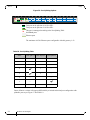
Figure 36: Port Splitting Options . . . . . . . . . . . . . . . . . . . . . . . . . . . . . . . . . . . . . . . . . . . . . . . . . . .52
Figure 37: Port Splitting Options . . . . . . . . . . . . . . . . . . . . . . . . . . . . . . . . . . . . . . . . . . . . . . . . . . .53
Figure 38: 3 Examples of Port Mapping Assignment . . . . . . . . . . . . . . . . . . . . . . . . . . . . . . . . . . . .55
Figure 39: QSFP Connector Male and Female Views . . . . . . . . . . . . . . . . . . . . . . . . . . . . . . . . . . . .64

SwitchX 36-Port QSFP InfiniBand- Ethernet Gateway System Hardware User Manual Rev 1.0
Mellanox Technologies
7
List of Tables
Table 1: Revision History Table . . . . . . . . . . . . . . . . . . . . . . . . . . . . . . . . . . . . . . . . . . . . . . . . . . . .8
Table 2: Reference Documents and Web Sites . . . . . . . . . . . . . . . . . . . . . . . . . . . . . . . . . . . . . . . . .9
Table 3: General System Features . . . . . . . . . . . . . . . . . . . . . . . . . . . . . . . . . . . . . . . . . . . . . . . . .12
Table 4: Management Software . . . . . . . . . . . . . . . . . . . . . . . . . . . . . . . . . . . . . . . . . . . . . . . . . . .13
Table 5: Ethernet Features . . . . . . . . . . . . . . . . . . . . . . . . . . . . . . . . . . . . . . . . . . . . . . . . . . . . . . .13
Table 6: System Status LEDs . . . . . . . . . . . . . . . . . . . . . . . . . . . . . . . . . . . . . . . . . . . . . . . . . . . . .17
Table 7: Gateway Status LED Assignments . . . . . . . . . . . . . . . . . . . . . . . . . . . . . . . . . . . . . . . . . .19
Table 8: Fan Status LED Assignments . . . . . . . . . . . . . . . . . . . . . . . . . . . . . . . . . . . . . . . . . . . . . .20
Table 9: PS Unit Status LED Assignments . . . . . . . . . . . . . . . . . . . . . . . . . . . . . . . . . . . . . . . . . .21
Table 10: Bad Port LED Assignments . . . . . . . . . . . . . . . . . . . . . . . . . . . . . . . . . . . . . . . . . . . . . . .22
Table 11: Port Connector Physical and Logical Link Assignments for Ethernet Mode . . . . . . . . . .23
Table 12: Connector Physical and Logical Link Assignments for IB Mode . . . . . . . . . . . . . . . . . .24
Table 13: Air Flow Direction . . . . . . . . . . . . . . . . . . . . . . . . . . . . . . . . . . . . . . . . . . . . . . . . . . . . . .26
Table 14: Serial Terminal Program Configuration . . . . . . . . . . . . . . . . . . . . . . . . . . . . . . . . . . . . . .45
Table 15: Configuration Wizard Session - DHCP Configuration (Example) . . . . . . . . . . . . . . . . .45
Table 16: Configuration Wizard Session - Static IP Configuration . . . . . . . . . . . . . . . . . . . . . . . . .47
Table 17: Configuration Wizard Session - Zeroconf Configuration . . . . . . . . . . . . . . . . . . . . . . . .48
Table 18: Port Splitting Table . . . . . . . . . . . . . . . . . . . . . . . . . . . . . . . . . . . . . . . . . . . . . . . . . . . . . .52
Table 19: Port Splitting Options . . . . . . . . . . . . . . . . . . . . . . . . . . . . . . . . . . . . . . . . . . . . . . . . . . . .53
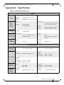
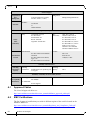
Table 20: SX6036G Specification Data . . . . . . . . . . . . . . . . . . . . . . . . . . . . . . . . . . . . . . . . . . . . . .59
Table 21: RJ-45 CONSOLE Pinout . . . . . . . . . . . . . . . . . . . . . . . . . . . . . . . . . . . . . . . . . . . . . . . . .65
Table 22: RJ-45 I2C Pinout . . . . . . . . . . . . . . . . . . . . . . . . . . . . . . . . . . . . . . . . . . . . . . . . . . . . . . .65
Table 23: OPNs for Replacement Parts . . . . . . . . . . . . . . . . . . . . . . . . . . . . . . . . . . . . . . . . . . . . . .66

Rev 1.0
Mellanox Technologies
8
Revision History
Table 1 - Revision History Table
Date Revision Description
August 2013 1.0 Initial Release

SwitchX 36-Port QSFP InfiniBand- Ethernet Gateway System Hardware User Manual Rev 1.0
Mellanox Technologies
9
About this Manual
This manual describes the installation and basic use of the Mellanox gateway which is based on
the SwitchX® -2 gateway device.
Intended Audience
This manual is intended for users and system administrators responsible for installing, running,
and managing switch platforms.
Related Documentation
Additional Documentation available from Mellanox:
All of these documents can be found on the Mellanox Website at www.mellanox.com. They are
available either through the product pages www.mellanox.com Products Select your prod-
uct or through the support page with a login and password.
Conventions
Throughout this manual, the name SX6036G and the term gateway are used to describe the gate-
way unless explicitly indicated otherwise.
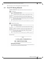
The following icons are used throughout this document to indicate information that is important
to the user.
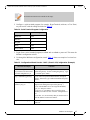
Table 2 - Reference Documents and Web Sites
Document Name Description
SwitchX®-2 Switch Product Hardware
Release Notes
For possible hardware issues see the switch support product page. This
document can be found on the support web page for this product.
This requires a customer support login. Look up the relevant SwitchX®-
based switch system/series release note file.
Mellanox MLNX-OS® Software User
Manual
This document contains information regarding configuring and manag-
ing Mellanox Technologies Switch Platforms.
MLNX-OS® Software Command Ref-
erence Guide
Command Reference Guide for MLNX-OS® listing all of the commands
available through MLNX-OS® with explanations and examples.
This icon makes recommendations to the user.
This icon indicates information that is helpful to the user.

Rev 1.0
Mellanox Technologies
10
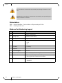
Abbreviations
FDR — Fourteen Data Rate – Used to indicate a 4X port running at 56 Gb/s.
FRU — Field Replaceable Unit
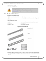
Mellanox Part Numbering Legend
This icon indicates a situation that can potentially cause damage to hardware or soft-
ware.
BEWARE! This icon indicates a situation that can potentially cause personal injury or
damage to hardware or software.
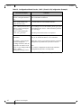
Place Field Decoder
M Mellanox Technologies
SX System Type SwitchX® switch Family
P Data Transfer Protocol
R Size of box 0 = 1U
1 = 1.5U
2 = 2U
C Data Rate G = Gateway
- Separator
P # Power Supplies 1=1, 2=2....
M Depth of the Unit S = standard depth, B = short depth
Y Air Flow direction R= Connector side to Power side airflow
F= Power Side side to Connector side airflow
R Chip Generation R – SwitchX
S – SwitchX-2

SwitchX 36-Port QSFP InfiniBand- Ethernet Gateway System Hardware User Manual Rev 1.0
Mellanox Technologies
11
1 Overview
Mellanox's InfiniBand to Ethernet gateway functionality built with Mellanox switches provides
the most cost-effective, high-performance solution for data center unified connectivity solutions.
Mellanox's gateways enable data centers to operate at up to 56Gb/s network speeds while seam
-
lessly connecting to 1, 10 and 40 Gigabit Ethernet networks. Existing LAN infrastructures and
management practices can be preserved, easing deployment and providing significant return-on-
investment.
With its high bandwidth, low-latency and reduced overhead, InfiniBand is the ideal choice for
speeding up application performance while simultaneously consolidating network and I/O infra
-
structure. Combining InfiniBand and Ethernet into a single solution provides the ideal rack back-
bone for next generation data centers.
Built with Mellanox's SwitchX®-based switches, the InfiniBand to Ethernet gateway software
license, or system, provides full port flexibility to choose between 56Gb/s InfiniBand to either
10, 40 and 56Gb/s Ethernet with low 400ns latency.
Together with Mellanox's ConnectX®-3 VPI interconnect adapters, IT managers can rely on
Mellanox as the most efficient end-to-end interconnect solution provider for their unified and
flexible InfiniBand and Ethernet data centers.
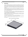
The SX6036G is a high-performance, low-latency 56Gb/s FDR InfiniBand to 40Gb/s Ethernet
gateway built with Mellanox's 6th generation SwitchX®-2 VPI switch device.
Installation, hot-swapping components and hardware maintenance is covered in “Basic Opera-
tion” on page 16.
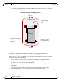
Figure 1: Connector Side View of the Gateway
427.9mm
Standarddepth628.9mm
Shortdepth428 .9mm
43.6

OverviewRev 1.0
Mellanox Technologies
12
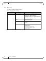
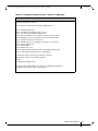
1.1 Features
The gateway includes the following features:
** This feature will be available to customers in the near future.
Table 3 - General System Features
Feature Description
Hardware features Network Interfaces • 36 QSPF+ interfaces
• Interface types –InfiniBand and Ethernet
• InfiniBand speed: FDR (56Gb/s); FDR10/QDR (40Gb/s);
DDR (20Gb/s); SDR (10Gb/s)
• Ethernet speed: 10/40/56 GbE
FRUs • Redundant power supplies
• Replaceable fan module
Compliance • Compliant with IBTA 1.2.1 and 1.3
• RoHS 6
Advanced Features • Congestion control**
• Adaptive routing**
• Port mirroring**
• Forward Error Correction -(FEC)
• Link Layer Retransmission -(LLR)
• Multiple SWIDs **

SwitchX 36-Port QSFP InfiniBand- Ethernet Gateway System Hardware User Manual Rev 1.0
Mellanox Technologies
13
Table 4 - Management Software
Feature Description
Management Software
(MLNX-OS®)
Software Management • Dual software image
• Software and firmware updates
File management •FTP
• TFTP
•SCP
Logging • Event history log
• SysLog support
Management Interface • DHCP/Zeroconf
•IPv6
Chassis Management • Monitoring environmental controls
• Power management
• Auto temperature control
• High availability
Network Management Inter-
faces
• SNMP v1,v2c,v3
• REST interfaces (XML Gateway)
Security •SSH
•Telnet
•RADIUS
• TACACS+
Date and Time •NTP
Cables & Transceivers • Transceiver info
Virtual Port Interconnect®
(VPI)
• Ethernet
• InfiniBand
Table 5 - Ethernet Features
Feature Description
General
• Jumbo Frames (9K)
• ACL - 24K rules (permit/deny)
• Breakout cables
Ethernet support
• 48K Unicast MAC addresses
• VLAN (802.1Q) - 4K
• LAG/LACP (802.3ad), 16 links per LAG (36 LAGs)
• Rapid Spanning Tree (802.1w)
• Flow control (802.3x)
• IGMP snooping v1,2
•LLDP
• ETS (802.1Qaz)
• PFC (802.1Qbb)
• Port mirroring

OverviewRev 1.0
Mellanox Technologies
14
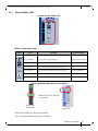
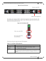
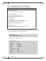
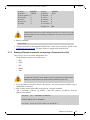
1.2 Serial Number and Product Version Information
The serial number, GUID and the MAC for the gateway are found on the pull out tab on the right
side of the Connector side panel below the CONSOLE connector. One MAC is for the mgmt0
management interface (the top Ethernet port). The second interface mgmt1 has the next consecu
-
tive MAC.
Figure 2: Pull Out Tab
1.3 Ethernet Ports
The gateway contains 8 ports of 40GbE. Each port can be connected with QSFP cables and con-
nectors for 40Gb/s speed, or 10Gb/s speed when connecting through QSA Mellanox adaptors.
Specific ports can be manually configured through the CLI management interface.
Each QSFP port is capable of up to 40GbE, upgradable to 56 GbE with a license, as well as
10GbE with a QSA, QSFP to SFP+ adapter or QSFP to SFP+ cables.
1.4 FDR Transmission Rate
Mellanox systems support FDR (fourteen data rate), an InfiniBand data rate, where each lane of a
4X port runs a bit rate of 14.0625 Gb/s with a 64b/66b encoding, resulting in an effective band
-
width of 56.25 Gb/s. The FDR physical layer is an IBTA specified physical layer using advanced
block types, deskew mechanism and framing rules for supporting higher speeds and increased
reliability.
40 GbE and 56 GbE are only guaranteed to work with approved cables and modules.
56GbE is operational on Mellanox 56Gb/s VPI cables only.
36
35
34
CONSOLE
MGT
1
2
SX6036G
S/N:MT1117X00014
P/N:MSX6036G‐2SFS
GUID:0002C9020040DDB0
MadeinIsrael
Rev:A1
MGT1:
00:02:C9:11:A2:01
322X6519220002
MGT2:
00:02:C9:11:A2:02
Pull out tab

SwitchX 36-Port QSFP InfiniBand- Ethernet Gateway System Hardware User Manual Rev 1.0
Mellanox Technologies
15
The gateways also supports FDR10, a non-standard InfiniBand data rate, where each lane of a 4X
port runs a bit rate of 10.3125 Gb/s with a 64b/66b encoding, resulting in an effective bandwidth
of 40 Gb/s.
FDR10 supports 20% more bandwidth over QDR using the same QSFP cables/connectors.
Both FDR and FDR10 support Forward Error Correction (FEC), as described in IEEE 802.3ap
chapter 74.
FDR and FDR10 are only guaranteed to work with approved Mellanox Cables.

Basic OperationRev 1.0
Mellanox Technologies
16
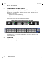
2 Basic Operation
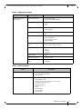
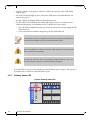
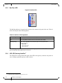
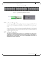
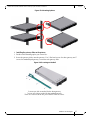
2.1 Gateway Platform Hardware Overview
Figure 3 shows the power side panel view of the gateway. The figure shows the hot-swap power
supply locations and the hot-swap fan module, and an I2C banana connector.
The figure below shows the connector side panel views of the gateway. The figure shows port
configurations for the systems.
• 2 – Ethernet RJ-45 connectors for management
• 1 – RJ-45 connector for connecting to a host PC
• 1 – USB connector.
All gateways have various status LEDs for on site status information.
Figure 3: Gateway System Power and Connector Side Panels
All connectivity except for power cords is via the connector side panel. All connectors can sup-
port active optical cables.
2.2 Status LEDs
The System Status LEDs are located to the left of the connectors on the connector side panel, and
on the power side at the far right.
OK
!
!
OK
OK
!
!
OK
12C
Power Side Panel
G

SwitchX 36-Port QSFP InfiniBand- Ethernet Gateway System Hardware User Manual Rev 1.0
Mellanox Technologies
17
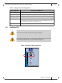
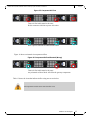
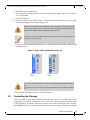
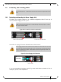
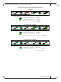
2.2.1 System Status LEDs
Figure 4: System Status LEDs
Figure 5: Gateway Status LEDs Front and Back
Both of these LEDs give identical information.
The system status LEDs should display as follows:
Table 6 - System Status LEDs
Symbol Name Description Normal Conditions
Gateway Status
Shows the health of the gateway
Solid green after 5 minutes
Fan Status LED
Shows the health of the fans Green
Power supply #1 Shows the health of the right side power supply unit Green
Power supply #2 Shows the health of the left side power supply unit
Depends on gateway
Bad Port LED lights up when a symbol error is detected Off
Unit Identifier LED Lights up on command through the CLI Off
PS1
PS2
UID
RST
Mellanox
®
PS1
PS2
UID
Power side
status LED
Connector side
status LED
Both of these LEDs show the
switch status.

Basic OperationRev 1.0
Mellanox Technologies
18
• when the gateway is plugged in, within five minutes the gateway status LED should
light up green
• the FAN LED should light up green. If the FAN LED shows red,troubleshoot the fan
module. See
page 57.
• the PS1 LED for the plugged in PS unit should light up green
• the PS2 LED for the second PS unit should light up green only if a second PS unit is
installed in the gateway for redundancy and it is connected to a power source
• if two PS units are installed and only one PS unit is connected to a power supply the PS2
LED will be red
• if only one PS unit is installed in the gateway, the PS2 LED will be off
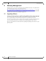
If the PS LEDs are not green, this indicates a problem with the power supplies. The gateway is
operational only if at least one of the PS LEDs is green.
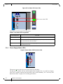
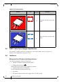
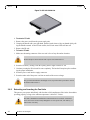
2.2.2 Gateway Status LED
Figure 6: Gateway Status LED
As long as there is power to the gateway (one PS unit is connected), and the gateway
is booted up and running, the gateway status LED should be green.
If the status LED shows red after five minutes, unplug the gateway and call your Mel-
lanox representative for assistance.
If the gateway shuts down due to over temperature, unplug the gateway, wait 5 min-
utes and replug in the gateway. For more information See page 57.
!
PS1
PS2
!
UID
RST
1
2
3
4

SwitchX 36-Port QSFP InfiniBand- Ethernet Gateway System Hardware User Manual Rev 1.0
Mellanox Technologies
19
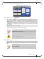
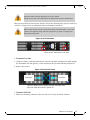
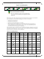
2.2.3 Fan Status LED
Figure 7: Fan Status LED Connector Side
Table 7 - Gateway Status LED Assignments
LED Configuration STATUS/ System Health LED
Solid Green OK – The system is up and running.
Flashing Green The system is booting up. This assignment is valid on managed systems only.
Solid Yellow To be implemented in a future SW release.
Solid Red
Major Error – Possible damage can result to the gateway. Turn off immediately.
e.g. bad firmware, can’t boot, overheated. If the system is booting up, it can take
up to 5 minutes for the status led to change to green.
Off Off – The system has no power.
All fans must be operating while the power supply is plugged in.
If the gateway shuts down due to over temperature, unplug the gateway, wait 5 min-
utes and replug in the gateway. For more information See page 57.
PS1
PS2
UID
RST
Mellanox
®

Basic OperationRev 1.0
Mellanox Technologies
20
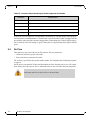
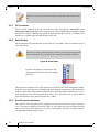
Figure 8: Fan Status LED Power Side
Table 8 shows the fan status LED assignment.
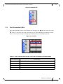
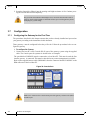
2.2.4 Power Supply Status LEDs
Figure 9: Power Status LED Connector Side
This gateway comes with two power supply units for redundancy.
The gateway is available with one factory installed Power Supply Unit. A second Power Supply
Unit can be added to support hot-swap ability and to add redundancy.
See “Accessory and
Replacement Parts” on page 66 for ordering part numbers.
Table 8 - Fan Status LED Assignments
LED Configuration FAN LED
Solid Green OK – All fans are up and running.
Solid Red Error – One or more fans is not operating properly. The system should be powered
down and troubleshoot the fan module.
Off Off – The fan unit is not receiving any power. Check that the fan unit is properly
and completely inserted.
PS1
PS2
UID
RST
Mellanox
®
!
This is a two color LED
RST
UID
PS2
PS1
Pagina se încarcă...
Pagina se încarcă...
Pagina se încarcă...
Pagina se încarcă...
Pagina se încarcă...
Pagina se încarcă...
Pagina se încarcă...
Pagina se încarcă...
Pagina se încarcă...
Pagina se încarcă...
Pagina se încarcă...
Pagina se încarcă...
Pagina se încarcă...
Pagina se încarcă...
Pagina se încarcă...
Pagina se încarcă...
Pagina se încarcă...
Pagina se încarcă...
Pagina se încarcă...
Pagina se încarcă...
Pagina se încarcă...
Pagina se încarcă...
Pagina se încarcă...
Pagina se încarcă...
Pagina se încarcă...
Pagina se încarcă...
Pagina se încarcă...
Pagina se încarcă...
Pagina se încarcă...
Pagina se încarcă...
Pagina se încarcă...
Pagina se încarcă...
Pagina se încarcă...
Pagina se încarcă...
Pagina se încarcă...
Pagina se încarcă...
Pagina se încarcă...
Pagina se încarcă...
Pagina se încarcă...
Pagina se încarcă...
Pagina se încarcă...
Pagina se încarcă...
Pagina se încarcă...
Pagina se încarcă...
Pagina se încarcă...
Pagina se încarcă...
Pagina se încarcă...
Pagina se încarcă...
Pagina se încarcă...
Pagina se încarcă...
Pagina se încarcă...
Pagina se încarcă...
Pagina se încarcă...
Pagina se încarcă...
Pagina se încarcă...
Pagina se încarcă...
Pagina se încarcă...
Pagina se încarcă...
Pagina se încarcă...
Pagina se încarcă...
Pagina se încarcă...
Pagina se încarcă...
Pagina se încarcă...
Pagina se încarcă...
Pagina se încarcă...
Pagina se încarcă...
Pagina se încarcă...
Pagina se încarcă...
Pagina se încarcă...
Pagina se încarcă...
Pagina se încarcă...
Pagina se încarcă...
Pagina se încarcă...
Pagina se încarcă...
Pagina se încarcă...
Pagina se încarcă...
-
 1
1
-
 2
2
-
 3
3
-
 4
4
-
 5
5
-
 6
6
-
 7
7
-
 8
8
-
 9
9
-
 10
10
-
 11
11
-
 12
12
-
 13
13
-
 14
14
-
 15
15
-
 16
16
-
 17
17
-
 18
18
-
 19
19
-
 20
20
-
 21
21
-
 22
22
-
 23
23
-
 24
24
-
 25
25
-
 26
26
-
 27
27
-
 28
28
-
 29
29
-
 30
30
-
 31
31
-
 32
32
-
 33
33
-
 34
34
-
 35
35
-
 36
36
-
 37
37
-
 38
38
-
 39
39
-
 40
40
-
 41
41
-
 42
42
-
 43
43
-
 44
44
-
 45
45
-
 46
46
-
 47
47
-
 48
48
-
 49
49
-
 50
50
-
 51
51
-
 52
52
-
 53
53
-
 54
54
-
 55
55
-
 56
56
-
 57
57
-
 58
58
-
 59
59
-
 60
60
-
 61
61
-
 62
62
-
 63
63
-
 64
64
-
 65
65
-
 66
66
-
 67
67
-
 68
68
-
 69
69
-
 70
70
-
 71
71
-
 72
72
-
 73
73
-
 74
74
-
 75
75
-
 76
76
-
 77
77
-
 78
78
-
 79
79
-
 80
80
-
 81
81
-
 82
82
-
 83
83
-
 84
84
-
 85
85
-
 86
86
-
 87
87
-
 88
88
-
 89
89
-
 90
90
-
 91
91
-
 92
92
-
 93
93
-
 94
94
-
 95
95
-
 96
96


Mellanox Technologies MSX6036G-2SFS Manual de utilizare
- Tip
- Manual de utilizare
- Acest manual este potrivit și pentru
în alte limbi
Lucrări înrudite
-
Mellanox Technologies SwitchX-2 MSX1012B-2BFS Manual de utilizare
-
-
-
-
-
-
-
-
-
Alte documente
-
SonicWALL NSsp 13700 – Appliance Only Manualul utilizatorului
-
LG PCS200R Manual de utilizare
-
 KYLAND Technology SICOM3000 Hardware Installation Manual
-
OLIGHT Obulb Pro S Rechargeable Multicolor Light Manual de utilizare
-
Cisco Systems MDS 9500 Manual de utilizare
-
SonicWALL TZ270 Instrucțiuni de utilizare
