
DOC023.98.90507
RTC module
06/2017, Edition 3
Basic User Manual
Basis-Benutzerhandbuch
Manuale di base per l'utente
Manuel d'utilisation de base
Manual básico del usuario
Manual de operações básicas
Základní návod k použití
Grundlæggende brugerhåndbog
Basisgebruikershandleiding
Podstawowa instrukcja obsługi
Grundläggande bruksanvisning
Основно ръководство за потребителя
Manualul de bază al utilizatorului
Temel Kullanım Kılavuzu
Osnovni uporabniški priročnik
Alapvető felhasználói útmutató
Βασικό εγχειρίδιο χειριστή

English..............................................................................................................................3
Deutsch.......................................................................................................................... 29
Italiano............................................................................................................................ 56
Français......................................................................................................................... 86
Español........................................................................................................................ 115
Português.................................................................................................................... 147
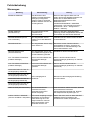
Čeština......................................................................................................................... 176
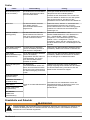
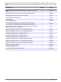
Dansk............................................................................................................................205
Nederlands................................................................................................................. 235
Polski............................................................................................................................ 264
Svenska....................................................................................................................... 293
български................................................................................................................... 319
Română....................................................................................................................... 349
Türkçe...........................................................................................................................380
Slovenski..................................................................................................................... 410
Magyar......................................................................................................................... 440
Ελληνικά...................................................................................................................... 469
2

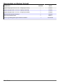
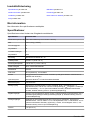
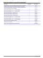
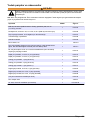
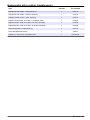
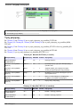
Table of contents
Specifications on page 3 Measurement values on page 21
General information on page 4 Troubleshooting on page 26
Installation on page 7 Replacement parts and accessories on page 27
Startup on page 19
Additional information
Additional information is available on the manufacturer's website.
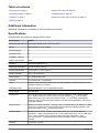
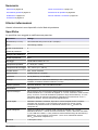
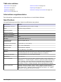
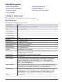
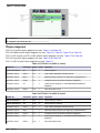
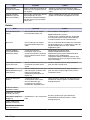
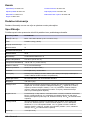
Specifications
Specifications are subject to change without notice.
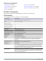
Specification Details
Dimensions (W x D x H) 120 x 350 x 96 mm (4.72 x 13.78 x 3.78 in.)
Weight Approximately 0.9 kg (1.98 lb)
Pollution degree 3
Protection class III
Installation category I
Degree of protection IP20
Mounting DIN rail EN 50022 35 x 15
Operating temperature 0 to 50 °C (32 to 122 °F)
Storage temperature –25 to +85 °C (–13 to +185 °F)
Relative humidity 95%, non-condensing
Flash memory CF compact flash card
Interface RJ 45 (Ethernet), 10/100 Mbit/s
Clock Internal, battery-buffered clock for time and date (Replace old batteries with the type
CR2032 Panasonic or similar)
Operating system Microsoft Windows
®
CE or Embedded Standard
Power supply 100–240 VAC
Analog input 0/4 to 20 mA for flow rate measurement; Internal resistance: 80 Ω + diode voltage
0.7 V; Signal current: 0 to 20 mA; Common mode voltage (U
CM
): 35 V maximum;
Measurement error (for entire measurement range): <± 0.3% (from measurement
range end value); Electrical surge resistance: 35 VDC; Electrical isolation: 500 V
eff
(K-
bus/signal voltage)
Digital outputs Aeration and alarm activation; Load type: ohmic, inductive lamp load; Maximum output
current: 0.5 A (short-circuit proof) for each channel; Reverse polarity protection: Yes;
Electrical isolation: 500 V
eff
(K-bus/field voltage)
Analog outputs Outputs for DO setpoint or VFD control; Signal current: 0/4 to 20 mA; Working
resistance: < 500 Ω; Measurement error: ± 0.5% LSB linearity error, ± 0.5% LSB offset
error, ± 0.5% (relative to the measuring range end value); Resolution: 12 bit;
Conversion time: 1.5 ms approximately; Electrical isolation: 500 V
eff
(K-bus/field
voltage)
Warranty 1 year (EU: 2 years)
English 3

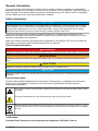
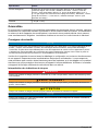
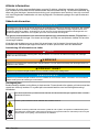
General information
In no event will the manufacturer be liable for direct, indirect, special, incidental or consequential
damages resulting from any defect or omission in this manual. The manufacturer reserves the right to
make changes in this manual and the products it describes at any time, without notice or obligation.
Revised editions are found on the manufacturer’s website.
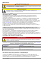
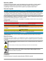
Safety information
N O T I C E
The manufacturer is not responsible for any damages due to misapplication or misuse of this product including,
without limitation, direct, incidental and consequential damages, and disclaims such damages to the full extent
permitted under applicable law. The user is solely responsible to identify critical application risks and install
appropriate mechanisms to protect processes during a possible equipment malfunction.
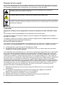
Please read this entire manual before unpacking, setting up or operating this equipment. Pay
attention to all danger and caution statements. Failure to do so could result in serious injury to the
operator or damage to the equipment.
Make sure that the protection provided by this equipment is not impaired. Do not use or install this
equipment in any manner other than that specified in this manual.
Use of hazard information
D A N G E R
Indicates a potentially or imminently hazardous situation which, if not avoided, will result in death or serious injury.
W A R N I N G
Indicates a potentially or imminently hazardous situation which, if not avoided, could result in death or serious
injury.
C A U T I O N
Indicates a potentially hazardous situation that may result in minor or moderate injury.
N O T I C E
Indicates a situation which, if not avoided, may cause damage to the instrument. Information that requires special
emphasis.
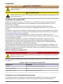
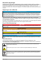
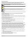
Precautionary labels
Read all labels and tags attached to the instrument. Personal injury or damage to the instrument
could occur if not observed. A symbol on the instrument is referenced in the manual with a
precautionary statement.
This symbol, if noted on the instrument, references the instruction manual for operation and/or safety
information.
This symbol indicates that a risk of electrical shock and/or electrocution exists.
Electrical equipment marked with this symbol may not be disposed of in European domestic or public
disposal systems. Return old or end-of-life equipment to the manufacturer for disposal at no charge to
the user.
Certification
Canadian Radio Interference-Causing Equipment Regulation, IECS-003, Class A:
4
English

Supporting test records reside with the manufacturer.
This Class A digital apparatus meets all requirements of the Canadian Interference-Causing
Equipment Regulations.
Cet appareil numérique de classe A répond à toutes les exigences de la réglementation canadienne
sur les équipements provoquant des interférences.
FCC Part 15, Class "A" Limits
Supporting test records reside with the manufacturer. The device complies with Part 15 of the FCC
Rules. Operation is subject to the following conditions:
1. The equipment may not cause harmful interference.
2. The equipment must accept any interference received, including interference that may cause
undesired operation.
Changes or modifications to this equipment not expressly approved by the party responsible for
compliance could void the user's authority to operate the equipment. This equipment has been tested
and found to comply with the limits for a Class A digital device, pursuant to Part 15 of the FCC rules.
These limits are designed to provide reasonable protection against harmful interference when the
equipment is operated in a commercial environment. This equipment generates, uses and can
radiate radio frequency energy and, if not installed and used in accordance with the instruction
manual, may cause harmful interference to radio communications. Operation of this equipment in a
residential area is likely to cause harmful interference, in which case the user will be required to
correct the interference at their expense. The following techniques can be used to reduce
interference problems:
1. Disconnect the equipment from its power source to verify that it is or is not the source of the
interference.
2. If the equipment is connected to the same outlet as the device experiencing interference, connect
the equipment to a different outlet.
3. Move the equipment away from the device receiving the interference.
4. Reposition the receiving antenna for the device receiving the interference.
5. Try combinations of the above.
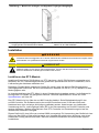
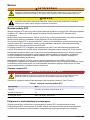
Product overview
N O T I C E
The use of a Real-Time Controller (RTC) module does not replace system maintenance. Make sure that all
instruments connected to the RTC open/closed-loop controller are always in good condition. Regular
maintenance is necessary to make sure that the instruments supply correct, reliable measurement values. Refer
to the user documentation of each instrument.
RTC modules are general application control units that makes some processes better in treatment
plants. RTC modules are available as 1-channel, 2-channel or multi-channel systems.
Multi-channel RTC modules are usually operated on industrial PCs (IPC) and all input/output signals
are transferred through the sc1000 controller. Refer to the sc1000 documentation. Refer to the
documentation supplied with the hardware.
Product components
N O T I C E
The combination of pre-assembled components supplied by the manufacturer does not show an independently-
functioning unit. In accordance with EU guidelines, this combination of pre-assembled components is not supplied
with a CE mark, and there is no EU declaration of conformity for the combination. However, the conformity of the
combination of components with the guidelines can be proved through technical measurements.
Make sure that all components have been received. If any items are missing or damaged, contact the
manufacturer or a sales representative immediately.
Each RTC module is supplied with a:
• SUB-D connector (9 pin)
English
5

• Ferrite core (foldable)
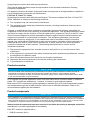
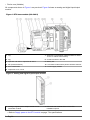
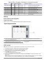
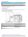
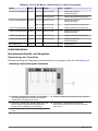
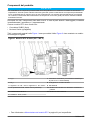
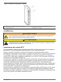
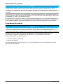
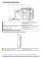
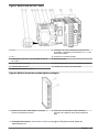
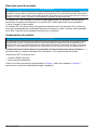
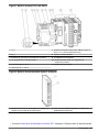
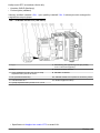
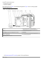
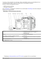
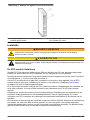
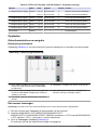
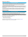
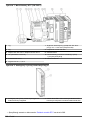
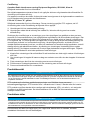
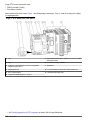
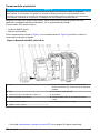
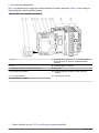
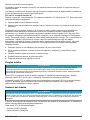
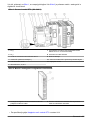
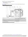
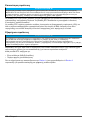
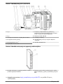
All components shown in Figure 1 are pre-wired. Figure 2 shows an analog and digital input/output
module.
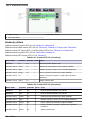
Figure 1 RTC base module (100–240 V)
1 L(+) 7 Automatic circuit breaker (ON/OFF switch for items
10 and 11 without fuse function)
2 N(-) 8 sc1000 connection: RS-485
3 Input AC 100–240 V / Input DC 95–250 V 9 Battery slot
4 PE (Protective Earth) 10 CPU base module with a passive aeration element
5 24 V transformer
1
11 Power supply module
6 Output DC 24 V, 0.75 A
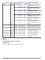
Figure 2 Analog and digital input/output module
1 Analog or digital input or output module or bus
termination module.
2 LED area with installed LEDs or free LED
installation spaces.
1
Refer to Supply power to the RTC module on page 7 for specifications.
6 English

Installation
W A R N I N G
Potential Electrocution Hazard. Only qualified personnel should conduct the tasks described in this
section of the manual.
C A U T I O N
Possible danger to sensor or logger. Always disconnect power to the instrument when making any
electrical connections.
Install the RTC module
Only install RTC DIN rail versions on a DIN rail. Only install an IPC panel mount versions according
to the IPC manufacturer specifications that are supplied with the hardware.
Attach the module horizontally. Make sure that the passive aeration element operates correctly.
Make sure that there is a minimum of 30 mm (1.2 in.) of space around the module.
To use the RTC module indoors, install the module in a control cabinet. To use the RTC module
outdoors, install the module in an enclosure. Refer to Specifications on page 3 for the enclosure
specifications.
An sc1000 controller is necessary to operate the RTC module. Refer to the sc1000 controller
documentation. It is necessary to use software version V2.30 (or higher) for the sc1000 controller.
Hardware is subject to change without notice. Refer to the sc1000 documentation and other
hardware documentation for input/output electrical wiring. Additional information of RTC controllers
and setting parameters is available on the manufacturer's website.
This instrument is rated for an altitude of 2000 m (6562 ft) maximum. Use of this instrument at an
altitude higher than 2000 m can slightly increase the potential for the electrical insulation to break
down, which can result in an electric shock hazard. The manufacturer recommends that users with
concerns contact technical support.
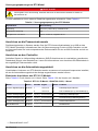
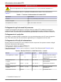
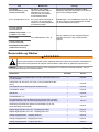
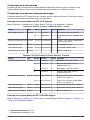
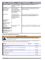
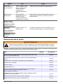
Supply power to the RTC module
D A N G E R
Electrocution hazard. Do not connect AC power directly to a DC powered instrument.
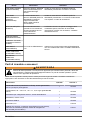
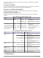
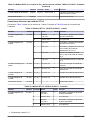
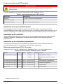
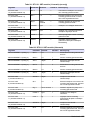
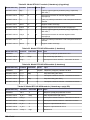
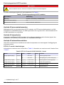
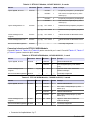
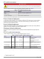
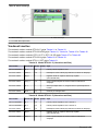
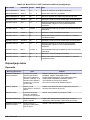
An external deactivation switch is necessary for all installations. Refer to Table 1.
Table 1 Supply voltage of the RTC module
Specification Description
Voltage 24 V DC (-15%/+20%), maximal 25 W
Recommended fuse C2
With 110–240 V option 240 V, 50–60 Hz, approximately 25 VA
Connect to the process instruments
The measurement signals of the sc sensors are supplied to the RTC module through the RTC
communication card in the sc1000. For information about the power supply of the sc1000 controller
and the sc sensors, refer to the applicable documentation for the sc1000 controller and sc sensors.
English
7

Connect to the controller
Attach the supplied SUB-D connector to a two-wire, shielded data cable (signal or bus cable). Refer
to the applicable documentation for the data cable connection.
Connect to the automation unit
Different versions of RTC modules are installed with other components that can connect to the
automation unit of the plant.
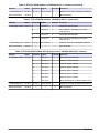
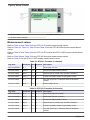
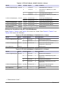
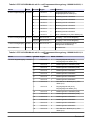
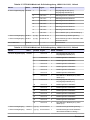
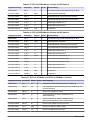
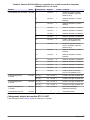
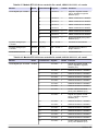
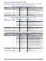
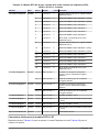
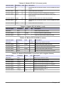
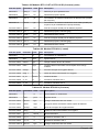
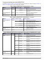
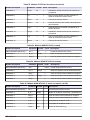
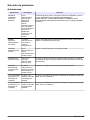
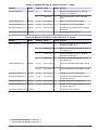
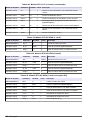
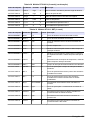
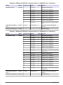
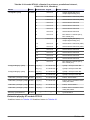
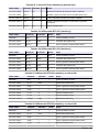
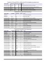
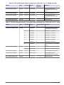
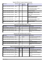
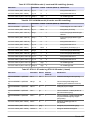
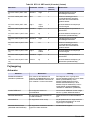
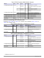
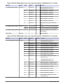
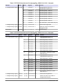
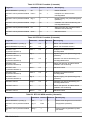
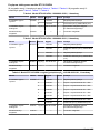
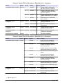
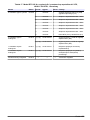
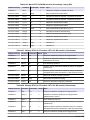
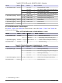
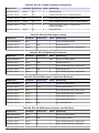
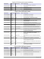
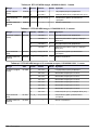
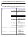
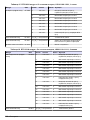
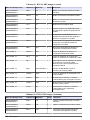
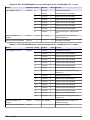
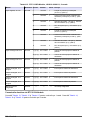
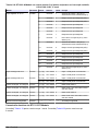
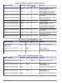
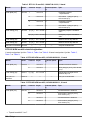
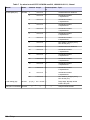
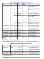
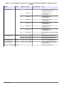
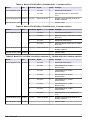
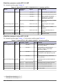
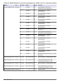
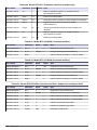
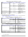
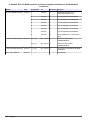
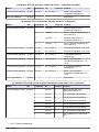
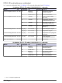
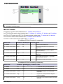
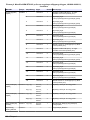
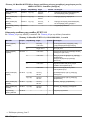
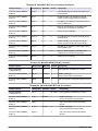
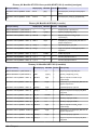
RTC101 P-module electrical connections
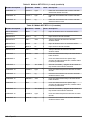
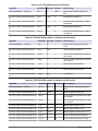
Refer to Table 2 for the 1-channel version. Refer to Table 3 for the 2-channel version.
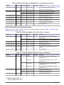
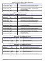
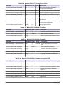
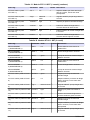
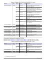
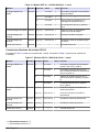
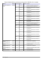
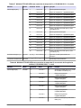
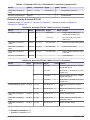
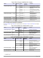
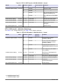
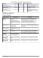
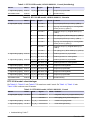
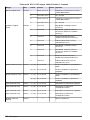
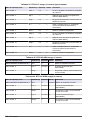
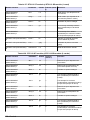
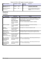
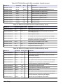
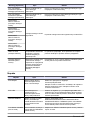
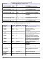
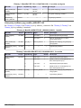
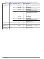
Table 2 RTC101 P-module, LXV407.99.01010, 1-channel
Module Name Terminal Signal Channel Function
2-fold digital output
2
KL2032 1 +24 V/0 V 1 Precipitant pump ON/OFF
5 +24 V/0 V 1 RTC operating (24 V), RTC defective (0 V)
1-fold analog output KL4011 1(+) 3(-) 0/4 to 20 mA 1 Precipitant pump dosing rate
1-fold analog input KL3011 1(+) 2(-) 0/4 to 20 mA 1 Flow rate aeration lane
1-fold analog input KL3011 1(+) 2(-) 0/4 to 20 mA 1 Supply volume flow
Bus end terminal KL9010 — — — Bus termination
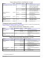
Table 3 RTC101 P-module, LXV407.99.01011, 2-channels
Module Name Terminal Signal Channel Function
4-fold digital output
3
KL2134 1 +24 V/0 V 1 Precipitant pump 1 ON/OFF
5 +24 V/0 V 1 RTC channel 1 operating (24 V), RTC
defective (0 V)
4 +24 V/0 V 2 Precipitant pump 2 ON/OFF
8 +24 V/0 V 2 RTC channel 2 operating (24 V), RTC
defective (0 V)
2-fold analog output KL4012 1(+) 3(-) 0/4 to 20 mA 1 Precipitant pump 1 dosing rate
5(+) 7(-) 0/4 to 20 mA 2 Precipitant pump 2 dosing rate
1-fold analog input KL3011 1(+) 2(-) 0/4 to 20 mA 1 Supply volume flow Channel 1
2-fold analog input KL3011 1(+) 2(-) 0/4 to 20 mA 1 Supply volume flow Channel 2
Bus end terminal KL9010 — — — Bus termination
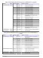
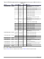
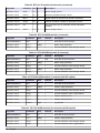
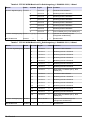
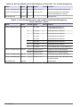
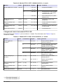
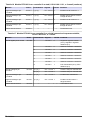
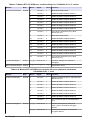
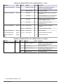
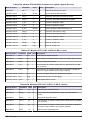
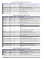
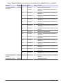
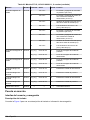
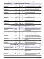
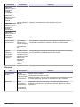
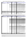
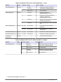
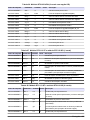
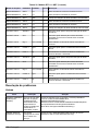
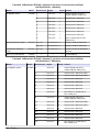
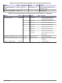
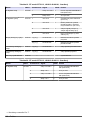
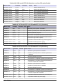
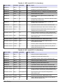
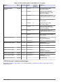
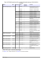
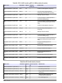
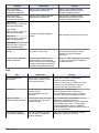
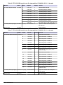
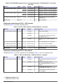
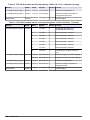
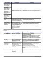
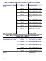
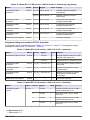
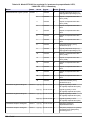
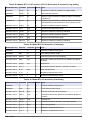
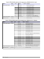
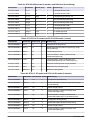
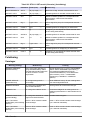
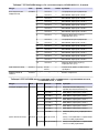
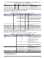
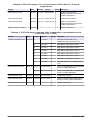
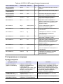
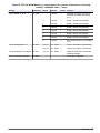
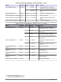
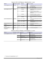
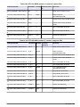
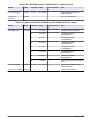
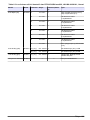
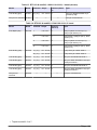
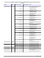
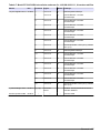
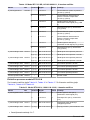
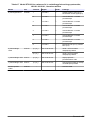
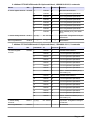
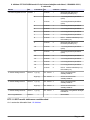
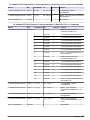
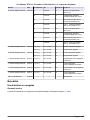
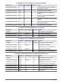
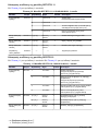
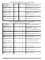
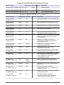
RTC105 N/DN-module electrical connections
Refer to Table 4, Table 6 and Table 8 for 1-channel versions. Refer to Table 5, Table 7 and Table 9
for 2-channel versions.
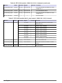
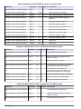
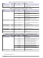
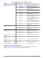
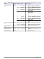
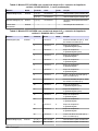
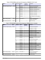
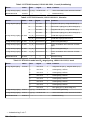
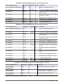
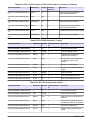
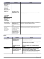
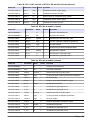
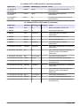
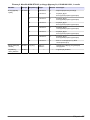
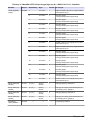
Table 4 RTC105 N/DN-module, LXV408.99.20101, 1-channel
Module Name Terminal Signal Channel Function
2-fold digital output KL2032 1 +24 V/0 V 1 Nitrification/denitrification
5 +24 V/0 V 1 RTC operating (24 V), RTC defective (0 V)
2
Ground connectors 3 and 7.
3
Ground connectors 3 and 7.
8 English

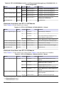
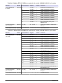
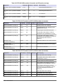
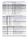
Table 4 RTC105 N/DN-module, LXV408.99.20101, 1-channel (continued)
Module Name Terminal Signal Channel Function
1-fold analog input KL3011 1(+) 2(-) 0/4 to 20 mA 1 Optional: Flow rate to biological treatment
Bus end terminal KL9010 — — — Bus termination
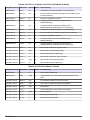
Table 5 RTC105 N/DN-module, LXV408.99.20111, 2-channels
Module Name Terminal Signal Channel Function
4-fold digital output KL2134 1 +24 V/0 V 1 Nitrification/denitrification
5 +24 V/0 V 1 RTC channel 1 operating (24 V), RTC
defective (0 V)
4 +24 V/0 V 2 Nitrification/denitrification
8 +24 V/0 V 2 RTC channel 2 operating (24 V), RTC
defective (0 V)
1-fold analog input KL3011 1(+) 2(-) 0/4 to 20 mA 1 Optional: Flow rate to biological treatment
Bus end terminal KL9010 — — — Bus termination
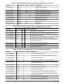
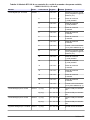
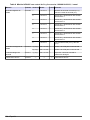
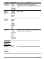
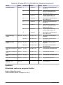
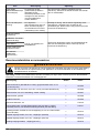
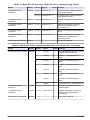
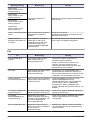
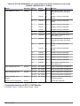
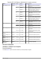
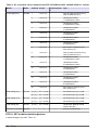
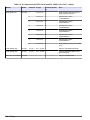
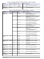
Table 6 RTC105 N/DN-module with O
2
step control, LXV408.99.21101,1-channel
Module Name Terminal Signal Channel Function
8-fold digital output KL2408 1 +24 V/0 V 1 Nitrification/denitrification
5 +24 V/0 V 1 Aeration step 2 ON/OFF
2 +24 V/0 V 1 Aeration step 4 ON/OFF
6 +24 V/0 V 1 Aeration step 6 ON/OFF
3 +24 V/0 V 1 Aeration step 1 ON/OFF
7 +24 V/0 V 1 Aeration step 3 ON/OFF
4 +24 V/0 V 1 Aeration step 5 ON/OFF
8 +24 V/0 V 1 RTC operating (24 V), RTC defective (0 V)
1-fold analog input KL3011 1(+) 2(-) 0/4 to 20 mA 1 Optional: Flow rate to biological treatment
Bus end terminal KL9010 — — — Bus termination
English 9

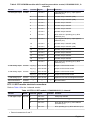
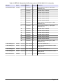
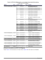
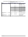
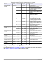
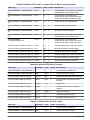
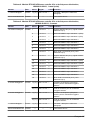
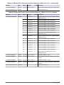
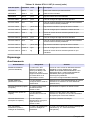
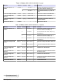
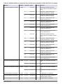
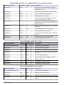
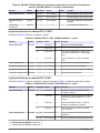
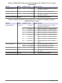
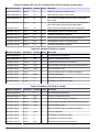
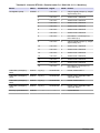
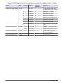
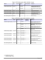
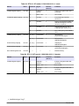
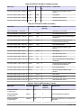
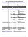
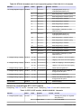
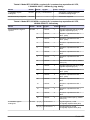
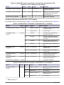
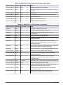
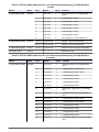
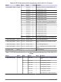
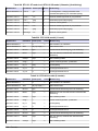
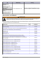
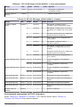
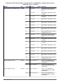
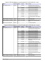
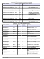
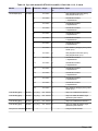
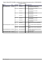
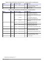
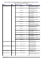
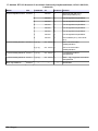
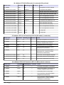
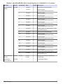
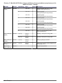
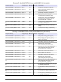
Table 7 RTC105 N/DN-module with O
2
step control, LXV408.99.21111, 2-channels
Module Name Terminal Signal Channel Function
16-fold digital output KL2809 1 +24 V/0 V 1 Nitrification/denitrification
2 +24 V/0 V 1 Aeration step 1 ON/OFF
3 +24 V/0 V 1 Aeration step 2 ON/OFF
4 +24 V/0 V 1 Aeration step 3 ON/OFF
5 +24 V/0 V 1 Aeration step 4 ON/OFF
6 +24 V/0 V 1 Aeration step 5 ON/OFF
7 +24 V/0 V 1 Aeration step 6 ON/OFF
8 +24 V/0 V 1 RTC channel 1 operating (24 V), RTC
defective (0 V)
9 +24 V/0 V 2 Nitrification/denitrification
10 +24 V/0 V 2 Aeration step 1 ON/OFF
11 +24 V/0 V 2 Aeration step 2 ON/OFF
12 +24 V/0 V 2 Aeration step 3 ON/OFF
13 +24 V/0 V 2 Aeration step 4 ON/OFF
14 +24 V/0 V 2 Aeration step 5 ON/OFF
15 +24 V/0 V 2 Aeration step 6 ON/OFF
16 +24 V/0 V 2 RTC channel 2 operating (24 V), RTC
defective (0 V)
1-fold analog input KL3011 1(+) 2(-) 0/4 to 20 mA 1 Optional: Flow rate to biological treatment
Bus end terminal KL9010 — — — Bus termination
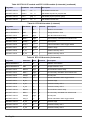
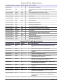
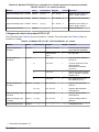
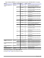
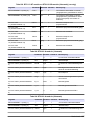
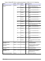
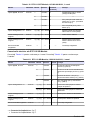
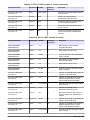
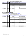
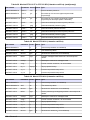
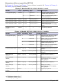
Table 8 RTC105 N/DN-module with O
2
and frequence drive control, LXV408.99.22101, 1-
channel
Module Name Terminal Signal Channel Function
8-fold digital output KL2408 1 +24 V/0 V 1 Input Signals OK (24 V), Input signal is
defective (0 V)
5 +24 V/0 V 1 Aeration step 1 ON/OFF
2 +24 V/0 V 1 Aeration step 2 ON/OFF
6 +24 V/0 V 1 Aeration step 3 ON/OFF
3 +24 V/0 V 1 Aeration step 4 ON/OFF
7 +24 V/0 V 1 Aeration step 5 ON/OFF
4 +24 V/0 V 1 Aeration step 6 ON/OFF
8 +24 V/0 V 1 RTC operating (24 V), RTC defective (0 V)
2-fold analog output KL4012 1(+) 3(-) 0/4 to 20 mA 1 Output 1 VFD for DO control
5(+) 3(-) 0/4 to 20 mA 1 Output 2 VFD for DO control
1-fold analog input KL3011 1(+) 2(-) 0/4 to 20 mA 1 Optional: Flow rate to biological treatment
Bus end terminal KL9010 — — — Bus termination
10 English

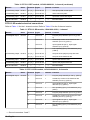
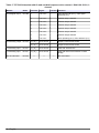
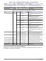
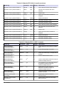
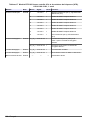
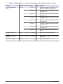
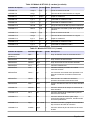
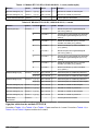
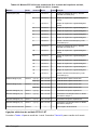
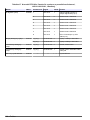
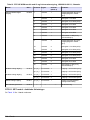
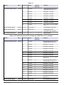
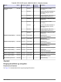
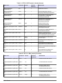
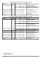
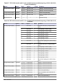
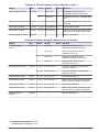
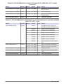
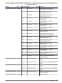
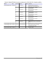
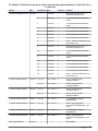
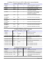
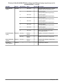
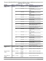
Table 9 RTC105 N/DN-module with O
2
and frequence drive control, LXV408.99.22111, 2-
channels
Module Name Terminal Signal Channel Function
16-fold digital output KL2809 1 +24 V/0 V 1 Input Signals OK (24 V), Input signal is
defective (0 V)
2 +24 V/0 V 1 Aeration step 1 ON/OFF (VFD)
3 +24 V/0 V 1 Aeration step 2 ON/OFF (VFD)
4 +24 V/0 V 1 Aeration step 3 ON/OFF
5 +24 V/0 V 1 Aeration step 4 ON/OFF
6 +24 V/0 V 1 Aeration step 5 ON/OFF
7 +24 V/0 V 1 Aeration step 6 ON/OFF
8 +24 V/0 V 1 RTC channel 1 operating (24 V), RTC
defective (0 V)
9 +24 V/0 V 2 Input Signals OK (24 V), Input signal is
defective (0 V)
10 +24 V/0 V 2 Aeration step 1 ON/OFF (VFD)
11 +24 V/0 V 2 Aeration step 2 ON/OFF (VFD)
12 +24 V/0 V 2 Aeration step 3 ON/OFF
13 +24 V/0 V 2 Aeration step 4 ON/OFF
14 +24 V/0 V 2 Aeration step 5 ON/OFF
15 +24 V/0 V 2 Aeration step 6 ON/OFF
16 +24 V/0 V 2 RTC channel 2 operating (24 V), RTC
defective (0 V)
2-fold analog output KL4012 1(+) 3(-) 0/4 to 20 mA 1 Output 1 VFD for DO control
5(+) 7(-) 0/4 to 20 mA 1 Output 2 VFD for DO control
2-fold analog output KL4012 1(+) 3(-) 0/4 to 20 mA 2 Output 1 VFD for DO control
5(+) 7(-) 0/4 to 20 mA 2 Output 2 VFD for DO control
1-fold analog input KL3011 1(+) 2(-) 0/4 to 20 mA 1 Optional: Flow rate to biological treatment
Bus end terminal KL9010 — — — Bus termination
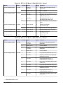
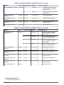
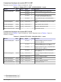
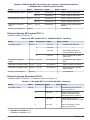
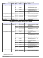
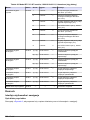
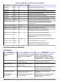
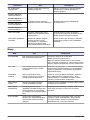
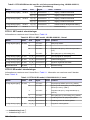
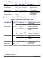
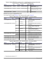
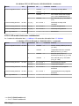
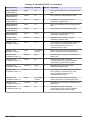
RTC111 SRT-module electrical connections
Refer to Table 10 for the 1-channel version.
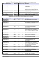
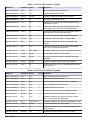
Table 10 RTC111 SRT-module, LXV409.99.00101, 1-channel
Module Name Terminal Signal Channel Function
4-fold digital output
4
KL2134 1 +24 V/0 V 1 SAS pump ON/OFF
2 +24 V/0 V 1 —
3 +24 V/0 V 1 RTC gets all input (24 V), RTC fallback
procedure (0 V)
4 +24 V/0 V 1 RTC operating (24 V), RTC defective (0 V)
4
Ground connectors 3 and 7.
English 11

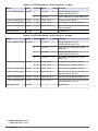
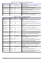
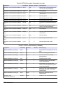
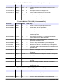
Table 10 RTC111 SRT-module, LXV409.99.00101, 1-channel (continued)
Module Name Terminal Signal Channel Function
1-fold analog output KL4011 1(+) 3(-) 0/4 to 20 mA 1 SAS pump VFD control signal
1-fold analog input KL3011 1(+) 2(-) 0/4 to 20 mA 1 Inflow volume to plant
1-fold analog input KL3011 1(+) 2(-) 0/4 to 20 mA 1 Input SAS volume flow signal
Bus end terminal KL9010 — — — Bus termination
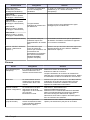
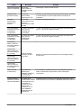
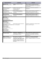
RTC112 SD-module electrical connections
Refer to Table 11 for the 1-channel version. Refer to Table 12 for the 2-channel version.
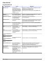
Table 11 RTC112 SD-module, LXV410.99.00101, 1-channel
Module Name Terminal Signal Channel Function
4-fold digital output
5
KL2134 1 +24 V/0 V 1 Polymer pump ON/OFF (24 V/0 V); (LED
a)
2 +24 V/0 V 1 Closed-loop control of the feed flow rate
ON/OFF (24 V/0 V); (LED c)
3 +24 V/0 V 1 Input signals OK (24 V), input signal
defective (0 V); (LED b)
4 +24 V/0 V 1 RTC operating (24 V), RTC defective (0 V),
(LED d)
2-fold analog output KL4012 1(+) 3(-) 0/4 to 20 mA 1 Set point of the polymer pump flow rate
5(+) 7(-) 0/4 to 20 mA 1 Set point of the feed flow rate
1-fold analog input KL3011 1(+) 2(-) 0/4 to 20 mA 1 Input of the feed flow rate
1-fold analog input KL3011 1(+) 2(-) 0/4 to 20 mA 1 Input of the polymer flow rate
Bus end terminal KL9010 — — — Bus termination
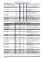
Table 12 RTC112 SD-module, LXV410.99.00111, 2-channels
Module Name Terminal Signal Channel Function
8-fold digital output KL2408 1 +24 V/0 V 1 Polymer pump ON/OFF(24 V/0 V); (LED a)
5 +24 V/0 V 1 Closed-loop control of the feed flow rate
ON/OFF (24 V/0 V); (LED e)
2 +24 V/0 V 1 Input signals OK (24 V), input signal
defective (0 V); (LED b)
6 +24 V/0 V 1 RTC operating (24 V), RTC defective (0 V),
(LED f)
3 +24 V/0 V 2 Polymer pump ON/OFF (24 V/0 V); (LED c)
7 +24 V/0 V 2 Closed-loop control of the supply flow rate
ON/OFF (24 V/0 V); (LED g)
4 +24 V/0 V 2 Input signals OK (24 V), input signal
defective (0 V); (LED d)
8 +24 V/0 V 2 RTC operating (24 V), RTC defective (0 V),
(LED h)
5
Ground connectors 3 and 7.
12 English

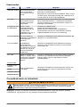
Table 12 RTC112 SD-module, LXV410.99.00111, 2-channels (continued)
Module Name Terminal Signal Channel Function
2-fold analog output KL4012 1(+) 3(-) 0/4 to 20 mA 1 Set point of the polymer flow rate
5(+) 7(-) 0/4 to 20 mA 1 Set point of the feed flow rate
2-fold analog output KL4012 1(+) 3(-) 0/4 to 20 mA 2 Set point of the polymer flow rate
5(+) 7(-) 0/4 to 20 mA 2 Set point of the feed flow rate
1-fold analog input KL3011 1(+) 2(-) 0/4 to 20 mA 1 Input of the feed flow rate
1-fold analog input KL3011 1(+) 2(-) 0/4 to 20 mA 1 Input of the polymer flow rate
1-fold analog input KL3011 1(+) 2(-) 0/4 to 20 mA 2 Input of the feed flow rate
1-fold analog input KL3011 1(+) 2(-) 0/4 to 20 mA 2 Input of the polymer flow rate
Bus end terminal KL9010 — — — Bus termination
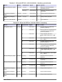
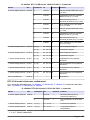
RTC103 N-module electrical connections
Refer to Table 13, Table 15 and Table 17 for 1-channel versions. Refer to Table 14, Table 16 and
Table 18 for 2-channel versions.
Table 13 RTC103 N-module, LXV411.99.10101, 1-channel
Module Name Terminal Signal Channel Function
2-fold digital output
6
KL2032 1 +24 V/0 V 1 Input Signals OK (24 V), Input signal
defective (0 V)
5 +24 V/0 V 1 RTC operating (24 V), RTC defective (0 V)
1-fold analog output KL4011 1(+) 3(-) 0/4 to 20 mA 1 Output DO set point
1-fold analog input KL3011 1(+) 2(-) 0/4 to 20 mA 1 Flow rate aeration lane
1-fold analog input KL3011 1(+) 2(-) 0/4 to 20 mA 1 Flow rate internal recirculation or return
sludge
Bus end terminal KL9010 — — — Bus termination
Table 14 RTC103 N-module, LXV411.99.10111, 2-channels
Module Name Terminal Signal Channel Function
4-fold digital output
7
KL2134 1 +24 V/0 V 1 Input Signals OK (24 V), Input signal
defective (0 V)
5 +24 V/0 V 1 RTC channel 1 operating (24 V), RTC
defective (0 V)
4 +24 V/0 V 2 Input Signals OK (24 V), Input signal
defective (0 V)
8 +24 V/0 V 2 RTC channel 2 operating (24 V), RTC
defective (0 V)
2-fold analog output KL4012 1(+) 3(-) 0/4 to 20 mA 1 Output DO set point lane 1
5(+) 3(-) 0/4 to 20 mA 2 Output DO set point lane 2
1-fold analog input KL3011 1(+) 2(-) 0/4 to 20 mA 1 Flow rate aeration lane 1
6
Ground connectors 3 and 7.
7
Ground connectors 3 and 7.
English 13

Table 14 RTC103 N-module, LXV411.99.10111, 2-channels (continued)
Module Name Terminal Signal Channel Function
1-fold analog input KL3011 1(+) 2(-) 0/4 to 20 mA 1 Flow rate internal recirculation or return
sludge lane 1
1-fold analog input KL3011 1(+) 2(-) 0/4 to 20 mA 2 Flow rate aeration lane 2
1-fold analog input KL3011 1(+) 2(-) 0/4 to 20 mA 2 Flow rate internal recirculation or return
sludge lane 2
Bus end terminal KL9010 — — — Bus termination
Table 15 RTC103 N-module with O
2
step control, LXV411.99.11101,1-channel
Module Name Terminal Signal Channel Function
8-fold digital output KL2408 1 +24 V/0 V 1 Input Signals OK (24 V), Input signal
defective (0 V)
5 +24 V/0 V 1 Aeration step 1 ON/OFF
2 +24 V/0 V 1 Aeration step 2 ON/OFF
6 +24 V/0 V 1 Aeration step 3 ON/OFF
3 +24 V/0 V 1 Aeration step 4 ON/OFF
7 +24 V/0 V 1 Aeration step 5 ON/OFF
4 +24 V/0 V 1 Aeration step 6 ON/OFF
8 +24 V/0 V 1 RTC operating (24 V), RTC defective (0 V)
1-fold analog input KL3011 1(+) 2(-) 0/4 to 20 mA 1 Flow rate aeration lane
1-fold analog input KL3011 1(+) 2(-) 0/4 to 20 mA 1 Flow rate internal recirculation or return
sludge
Bus end terminal KL9010 — — — Bus termination
14 English

Table 16 RTC103 N-module with O
2
step control, LXV411.99.11111, 2-channels
Module Name Terminal Signal Channel Function
16-fold digital output KL2809 1 +24 V/0 V 1 Input Signals OK (24 V), Input signal
defective (0 V)
2 +24 V/0 V 1 Aeration step 1 ON/OFF
3 +24 V/0 V 1 Aeration step 2 ON/OFF
4 +24 V/0 V 1 Aeration step 3 ON/OFF
5 +24 V/0 V 1 Aeration step 4 ON/OFF
6 +24 V/0 V 1 Aeration step 5 ON/OFF
7 +24 V/0 V 1 Aeration step 6 ON/OFF
8 +24 V/0 V 1 RTC channel 1 operating (24 V), RTC
defective (0 V)
9 +24 V/0 V 2 Input Signals OK (24 V), Input signal
defective (0 V)
10 +24 V/0 V 2 Aeration step 1 ON/OFF
11 +24 V/0 V 2 Aeration step 2 ON/OFF
12 +24 V/0 V 2 Aeration step 3 ON/OFF
13 +24 V/0 V 2 Aeration step 4 ON/OFF
14 +24 V/0 V 2 Aeration step 5 ON/OFF
15 +24 V/0 V 2 Aeration step 6 ON/OFF
16 +24 V/0 V 2 RTC channel 2 operating (24 V), RTC
defective (0 V)
1-fold analog input KL3011 1(+) 2(-) 0/4 to 20 mA 1 Flow rate aeration lane 1
1-fold analog input KL3011 1(+) 2(-) 0/4 to 20 mA 1 Flow rate internal recirculation or return
sludge lane 1
1-fold analog input KL3011 1(+) 2(-) 0/4 to 20 mA 2 Flow rate aeration lane 2
1-fold analog input KL3011 1(+) 2(-) 0/4 to 20 mA 2 Flow rate internal recirculation or return
sludge lane 2
Bus end terminal KL9010 — — — Bus termination
English 15

Table 17 RTC103 N-module with O
2
and variable frequence drive control, LXV411.99.12101, 1-
channel
Module Name Terminal Signal Channel Function
8-fold digital output KL2408 1 +24 V/0 V 1 Input Signals OK (24 V), Input signal
defective (0 V)
5 +24 V/0 V 1 Aeration step 1 ON/OFF
2 +24 V/0 V 1 Aeration step 2 ON/OFF
6 +24 V/0 V 1 Aeration step 3 ON/OFF
3 +24 V/0 V 1 Aeration step 4 ON/OFF
7 +24 V/0 V 1 Aeration step 5 ON/OFF
4 +24 V/0 V 1 Aeration step 6 ON/OFF
8 +24 V/0 V 1 RTC operating (24 V), RTC defective (0 V)
2-fold analog output KL4012 1(+) 3(-) 0/4 to 20 mA 1 Output 1 VFD for DO control
5(+) 3(-) 0/4 to 20 mA 1 Output 2 VFD for DO control
1-fold analog input KL3011 1(+) 2(-) 0/4 to 20 mA 1 Flow rate aeration lane
1-fold analog input KL3011 1(+) 2(-) 0/4 to 20 mA 1 Flow rate internal recirculation or return
sludge
Bus end terminal KL9010 — — — Bus termination
16 English

Table 18 RTC103 N-module with O
2
and variable frequence drive control, LXV411.99.12111, 2-
channels
Module Name Terminal Signal Channel Function
16-fold digital output KL2809 1 +24 V/0 V 1 Input Signals OK (24 V), Input signal
defective (0 V)
2 +24 V/0 V 1 Aeration step 1 ON/OFF (VFD)
3 +24 V/0 V 1 Aeration step 2 ON/OFF (VFD)
4 +24 V/0 V 1 Aeration step 3 ON/OFF
5 +24 V/0 V 1 Aeration step 4 ON/OFF
6 +24 V/0 V 1 Aeration step 5 ON/OFF
7 +24 V/0 V 1 Aeration step 6 ON/OFF
8 +24 V/0 V 1 RTC channel 1 operating (24 V), RTC
defective (0 V)
9 +24 V/0 V 2 Input Signals OK (24 V), Input signal
defective (0 V)
10 +24 V/0 V 2 Aeration step 1 ON/OFF (VFD)
11 +24 V/0 V 2 Aeration step 2 ON/OFF (VFD)
12 +24 V/0 V 2 Aeration step 3 ON/OFF
13 +24 V/0 V 2 Aeration step 4 ON/OFF
14 +24 V/0 V 2 Aeration step 5 ON/OFF
15 +24 V/0 V 2 Aeration step 6 ON/OFF
16 +24 V/0 V 2 RTC channel 2 operating (24 V), RTC
defective (0 V)
2-fold analog output KL4012 1(+) 3(-) 0/4 to 20 mA 1 Output 1 VFD for DO control
5(+) 7(-) 0/4 to 20 mA 1 Output 2 VFD for DO control
2-fold analog output KL4012 1(+) 3(-) 0/4 to 20 mA 2 Output 1 VFD for DO control
5(+) 7(-) 0/4 to 20 mA 2 Output 2 VFD for DO control
1-fold analog input KL3011 1(+) 2(-) 0/4 to 20 mA 1 Flow rate aeration lane 1
1-fold analog input KL3011 1(+) 2(-) 0/4 to 20 mA 1 Flow rate internal recirculation or return
sludge lane 1
1-fold analog input KL3011 1(+) 2(-) 0/4 to 20 mA 2 Flow rate aeration lane 2
1-fold analog input KL3011 1(+) 2(-) 0/4 to 20 mA 2 Flow rate internal recirculation or return
sludge lane 2
Bus end terminal KL9010 — — — Bus termination
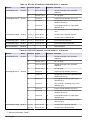
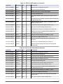
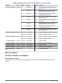
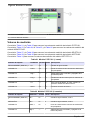
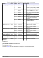
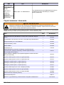
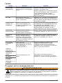
RTC113 ST-module electrical connections
Refer to Table 19 for the 1-channel version. Refer to Table 20 for the 2-channel version.
English
17

Table 19 RTC113 ST-module, LXV412.99.00101, 1-channel
Module Name Terminal Signal Channel Function
2-fold digital input KL1002 1 Input +24 V/0 V 1 Thickened sludge pump operation
(ON/OFF)
2 Source +24 V 1 24 V for relay
4-fold digital output
8
KL2134 1 +24 V/0 V 1 Polymer pump ON/OFF (24 V/0 V)
5 +24 V/0 V 1 Closed-loop control of the feed flow rate
ON/OFF (24 V/0 V)
2 +24 V/0 V 1 Input signals OK (24 V), input signal
defective (0 V)
6 +24 V/0 V 1 RTC operating (24 V), RTC defective
(0 V)
2-fold analog output KL4012 1(+) 3(-) 0/4 to 20 mA 1 Set point of the polymer flow rate
5(+) 7(-) 0/4 to 20 mA 1 Set point of the feed flow rate
1-fold analog input KL3011 1(+) 2(-) 0/4 to 20 mA 1 Input of the feed flow rate
1-fold analog input KL3011 1(+) 2(-) 0/4 to 20 mA 1 Input of the polymer flow rate
Bus end terminal KL9010 — — — Bus termination
Table 20 RTC113 ST-module, LXV412.99.00111, 2-channels
Module Name Terminal Signal Channel Function
2-fold digital input KL1002 1 Input +24 V/0 V 1 Thickened sludge pump operation
(ON/OFF)
2 Source +24 V 1 24 V for relay
5 Input +24 V/0 V 2 Thickened sludge pump operation
(ON/OFF)
6 Source +24 V 2 24 V for relay
8-fold digital output KL2408 1 +24 V/0 V 1 Polymer pump ON/OFF (24 V/0 V)
5 +24 V/0 V 1 Closed-loop control of the feed flow rate
ON/OFF (24 V/0 V)
2 +24 V/0 V 1 Input signals OK (24 V), input signal
defective (0 V)
6 +24 V/0 V 1 RTC channel 1 operating (24 V), RTC
defective (0 V)
3 +24 V/0 V 2 Polymer pump ON/OFF (24 V/0 V)
7 +24 V/0 V 2 Closed-loop control of the feed flow rate
ON/OFF (24 V/0 V)
4 +24 V/0 V 2 Input signals OK (24 V), input signal
defective (0 V)
8 +24 V/0 V 2 RTC channel 2 operating (24 V), RTC
defective (0 V)
2-fold analog output KL4012 1(+) 3(-) 0/4 to 20 mA 1 Set point of the polymer flow rate
5(+) 7(-) 0/4 to 20 mA 1 Set point of the feed flow rate
8
Ground connectors 3 and 7.
18 English

Table 20 RTC113 ST-module, LXV412.99.00111, 2-channels (continued)
Module Name Terminal Signal Channel Function
2-fold analog output KL4012 1(+) 3(-) 0/4 to 20 mA 2 Set point of the polymer flow rate
5(+) 7(-) 0/4 to 20 mA 2 Set point of the feed flow rate
1-fold analog input KL3011 1(+) 2(-) 0/4 to 20 mA 1 Input of the feed flow rate
1-fold analog input KL3011 1(+) 2(-) 0/4 to 20 mA 1 Input of the polymer flow rate
1-fold analog input KL3011 1(+) 2(-) 0/4 to 20 mA 2 Input of the feed flow rate
1-fold analog input KL3011 1(+) 2(-) 0/4 to 20 mA 2 Input of the polymer flow rate
Bus end terminal KL9010 — — — Bus termination
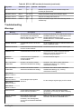
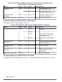
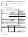
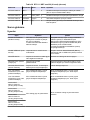
Startup
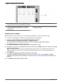
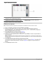
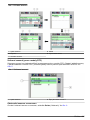
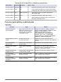
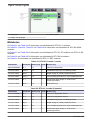
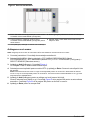
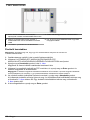
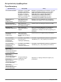
User interface and navigation
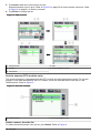
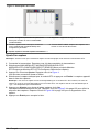
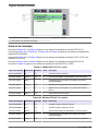
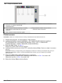
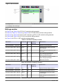
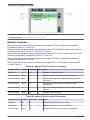
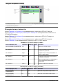
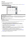
Keypad description
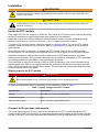
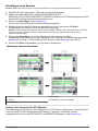
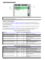
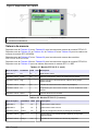
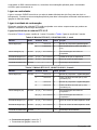
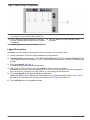
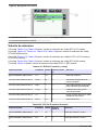
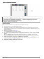
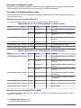
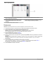
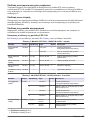
Refer to Figure 3 for the keypad description and navigation information.
Figure 3 Keypad description
1 Enter: Saves the setting and exits the current
screen to the CONFIGURE menu
4 Delete: Removes a sensor from the selection
2 Cancel: Exits the current screen to the
CONFIGURE menu without saving the setting
5 UP and DOWN arrows: Moves the sensors up or
down the list
3 Add: Adds a new sensor to the selection
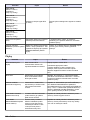
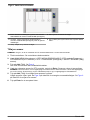
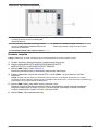
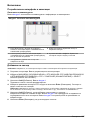
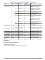
Add a sensor
Note: Make sure that an RTC communication card is installed in the sc1000 sensor module.
1. Connect the controller. Refer to the controller documentation.
2. Select MAIN MENU>RTC MODULES/PROGNOSYS>RTC
MODULES>RTC>CONFIGURE>SELECT SENSOR.
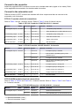
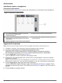
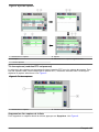
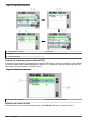
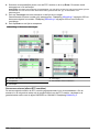
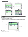
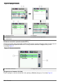
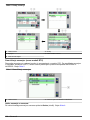
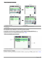
3. Push Add. Refer to Figure 4.
A list with all network connections shows.
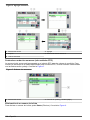
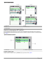
4. Select the applicable sensor for the RTC module and push Enter. The sensor is shown in the
sensor list.
Note: The sensor names in black are available for an RTC module. The sensor names in red are not available
for an RTC module. A sensor name identified with a "(p)" is available for PROGNOSYS.
English
19

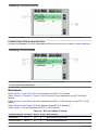
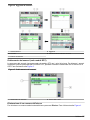
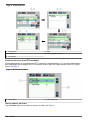
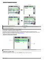
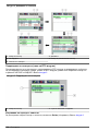
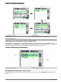
5. Push Add to add more sensors from the list.
Selected sensors show in gray. Refer to Figure 5 on page 20 to set the sensor sequence. Refer
to Figure 6 on page 21 to remove a sensor.
6. Push Enter to accept the list.
Figure 4 Add sensors
1 Select sensor 4 Add
2 Accept 5 Select additional sensor
3 Sensor list
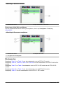
Sort the sensors (RTC modules only)
The sensor sequence is programmed in the RTC module for the measurement values. To sort the
sensors in the order specified for the RTC module, move the selected sensor with the UP and
DOWN arrows. Refer to Figure 5.
Figure 5 Sort the sensors
1 Select sensor 2 UP and DOWN arrows
Delete a sensor from the list
To delete a selected sensor from the list, push Delete. Refer to Figure 6.
20
English
Pagina se încarcă...
Pagina se încarcă...
Pagina se încarcă...
Pagina se încarcă...
Pagina se încarcă...
Pagina se încarcă...
Pagina se încarcă...
Pagina se încarcă...
Pagina se încarcă...
Pagina se încarcă...
Pagina se încarcă...
Pagina se încarcă...
Pagina se încarcă...
Pagina se încarcă...
Pagina se încarcă...
Pagina se încarcă...
Pagina se încarcă...
Pagina se încarcă...
Pagina se încarcă...
Pagina se încarcă...
Pagina se încarcă...
Pagina se încarcă...
Pagina se încarcă...
Pagina se încarcă...
Pagina se încarcă...
Pagina se încarcă...
Pagina se încarcă...
Pagina se încarcă...
Pagina se încarcă...
Pagina se încarcă...
Pagina se încarcă...
Pagina se încarcă...
Pagina se încarcă...
Pagina se încarcă...
Pagina se încarcă...
Pagina se încarcă...
Pagina se încarcă...
Pagina se încarcă...
Pagina se încarcă...
Pagina se încarcă...
Pagina se încarcă...
Pagina se încarcă...
Pagina se încarcă...
Pagina se încarcă...
Pagina se încarcă...
Pagina se încarcă...
Pagina se încarcă...
Pagina se încarcă...
Pagina se încarcă...
Pagina se încarcă...
Pagina se încarcă...
Pagina se încarcă...
Pagina se încarcă...
Pagina se încarcă...
Pagina se încarcă...
Pagina se încarcă...
Pagina se încarcă...
Pagina se încarcă...
Pagina se încarcă...
Pagina se încarcă...
Pagina se încarcă...
Pagina se încarcă...
Pagina se încarcă...
Pagina se încarcă...
Pagina se încarcă...
Pagina se încarcă...
Pagina se încarcă...
Pagina se încarcă...
Pagina se încarcă...
Pagina se încarcă...
Pagina se încarcă...
Pagina se încarcă...
Pagina se încarcă...
Pagina se încarcă...
Pagina se încarcă...
Pagina se încarcă...
Pagina se încarcă...
Pagina se încarcă...
Pagina se încarcă...
Pagina se încarcă...
Pagina se încarcă...
Pagina se încarcă...
Pagina se încarcă...
Pagina se încarcă...
Pagina se încarcă...
Pagina se încarcă...
Pagina se încarcă...
Pagina se încarcă...
Pagina se încarcă...
Pagina se încarcă...
Pagina se încarcă...
Pagina se încarcă...
Pagina se încarcă...
Pagina se încarcă...
Pagina se încarcă...
Pagina se încarcă...
Pagina se încarcă...
Pagina se încarcă...
Pagina se încarcă...
Pagina se încarcă...
Pagina se încarcă...
Pagina se încarcă...
Pagina se încarcă...
Pagina se încarcă...
Pagina se încarcă...
Pagina se încarcă...
Pagina se încarcă...
Pagina se încarcă...
Pagina se încarcă...
Pagina se încarcă...
Pagina se încarcă...
Pagina se încarcă...
Pagina se încarcă...
Pagina se încarcă...
Pagina se încarcă...
Pagina se încarcă...
Pagina se încarcă...
Pagina se încarcă...
Pagina se încarcă...
Pagina se încarcă...
Pagina se încarcă...
Pagina se încarcă...
Pagina se încarcă...
Pagina se încarcă...
Pagina se încarcă...
Pagina se încarcă...
Pagina se încarcă...
Pagina se încarcă...
Pagina se încarcă...
Pagina se încarcă...
Pagina se încarcă...
Pagina se încarcă...
Pagina se încarcă...
Pagina se încarcă...
Pagina se încarcă...
Pagina se încarcă...
Pagina se încarcă...
Pagina se încarcă...
Pagina se încarcă...
Pagina se încarcă...
Pagina se încarcă...
Pagina se încarcă...
Pagina se încarcă...
Pagina se încarcă...
Pagina se încarcă...
Pagina se încarcă...
Pagina se încarcă...
Pagina se încarcă...
Pagina se încarcă...
Pagina se încarcă...
Pagina se încarcă...
Pagina se încarcă...
Pagina se încarcă...
Pagina se încarcă...
Pagina se încarcă...
Pagina se încarcă...
Pagina se încarcă...
Pagina se încarcă...
Pagina se încarcă...
Pagina se încarcă...
Pagina se încarcă...
Pagina se încarcă...
Pagina se încarcă...
Pagina se încarcă...
Pagina se încarcă...
Pagina se încarcă...
Pagina se încarcă...
Pagina se încarcă...
Pagina se încarcă...
Pagina se încarcă...
Pagina se încarcă...
Pagina se încarcă...
Pagina se încarcă...
Pagina se încarcă...
Pagina se încarcă...
Pagina se încarcă...
Pagina se încarcă...
Pagina se încarcă...
Pagina se încarcă...
Pagina se încarcă...
Pagina se încarcă...
Pagina se încarcă...
Pagina se încarcă...
Pagina se încarcă...
Pagina se încarcă...
Pagina se încarcă...
Pagina se încarcă...
Pagina se încarcă...
Pagina se încarcă...
Pagina se încarcă...
Pagina se încarcă...
Pagina se încarcă...
Pagina se încarcă...
Pagina se încarcă...
Pagina se încarcă...
Pagina se încarcă...
Pagina se încarcă...
Pagina se încarcă...
Pagina se încarcă...
Pagina se încarcă...
Pagina se încarcă...
Pagina se încarcă...
Pagina se încarcă...
Pagina se încarcă...
Pagina se încarcă...
Pagina se încarcă...
Pagina se încarcă...
Pagina se încarcă...
Pagina se încarcă...
Pagina se încarcă...
Pagina se încarcă...
Pagina se încarcă...
Pagina se încarcă...
Pagina se încarcă...
Pagina se încarcă...
Pagina se încarcă...
Pagina se încarcă...
Pagina se încarcă...
Pagina se încarcă...
Pagina se încarcă...
Pagina se încarcă...
Pagina se încarcă...
Pagina se încarcă...
Pagina se încarcă...
Pagina se încarcă...
Pagina se încarcă...
Pagina se încarcă...
Pagina se încarcă...
Pagina se încarcă...
Pagina se încarcă...
Pagina se încarcă...
Pagina se încarcă...
Pagina se încarcă...
Pagina se încarcă...
Pagina se încarcă...
Pagina se încarcă...
Pagina se încarcă...
Pagina se încarcă...
Pagina se încarcă...
Pagina se încarcă...
Pagina se încarcă...
Pagina se încarcă...
Pagina se încarcă...
Pagina se încarcă...
Pagina se încarcă...
Pagina se încarcă...
Pagina se încarcă...
Pagina se încarcă...
Pagina se încarcă...
Pagina se încarcă...
Pagina se încarcă...
Pagina se încarcă...
Pagina se încarcă...
Pagina se încarcă...
Pagina se încarcă...
Pagina se încarcă...
Pagina se încarcă...
Pagina se încarcă...
Pagina se încarcă...
Pagina se încarcă...
Pagina se încarcă...
Pagina se încarcă...
Pagina se încarcă...
Pagina se încarcă...
Pagina se încarcă...
Pagina se încarcă...
Pagina se încarcă...
Pagina se încarcă...
Pagina se încarcă...
Pagina se încarcă...
Pagina se încarcă...
Pagina se încarcă...
Pagina se încarcă...
Pagina se încarcă...
Pagina se încarcă...
Pagina se încarcă...
Pagina se încarcă...
Pagina se încarcă...
Pagina se încarcă...
Pagina se încarcă...
Pagina se încarcă...
Pagina se încarcă...
Pagina se încarcă...
Pagina se încarcă...
Pagina se încarcă...
Pagina se încarcă...
Pagina se încarcă...
Pagina se încarcă...
Pagina se încarcă...
Pagina se încarcă...
Pagina se încarcă...
Pagina se încarcă...
Pagina se încarcă...
Pagina se încarcă...
Pagina se încarcă...
Pagina se încarcă...
Pagina se încarcă...
Pagina se încarcă...
Pagina se încarcă...
Pagina se încarcă...
Pagina se încarcă...
Pagina se încarcă...
Pagina se încarcă...
Pagina se încarcă...
Pagina se încarcă...
Pagina se încarcă...
Pagina se încarcă...
Pagina se încarcă...
Pagina se încarcă...
Pagina se încarcă...
Pagina se încarcă...
Pagina se încarcă...
Pagina se încarcă...
Pagina se încarcă...
Pagina se încarcă...
Pagina se încarcă...
Pagina se încarcă...
Pagina se încarcă...
Pagina se încarcă...
Pagina se încarcă...
Pagina se încarcă...
Pagina se încarcă...
Pagina se încarcă...
Pagina se încarcă...
Pagina se încarcă...
Pagina se încarcă...
Pagina se încarcă...
Pagina se încarcă...
Pagina se încarcă...
Pagina se încarcă...
Pagina se încarcă...
Pagina se încarcă...
Pagina se încarcă...
Pagina se încarcă...
Pagina se încarcă...
Pagina se încarcă...
Pagina se încarcă...
Pagina se încarcă...
Pagina se încarcă...
Pagina se încarcă...
Pagina se încarcă...
Pagina se încarcă...
Pagina se încarcă...
Pagina se încarcă...
Pagina se încarcă...
Pagina se încarcă...
Pagina se încarcă...
Pagina se încarcă...
Pagina se încarcă...
Pagina se încarcă...
Pagina se încarcă...
Pagina se încarcă...
Pagina se încarcă...
Pagina se încarcă...
Pagina se încarcă...
Pagina se încarcă...
Pagina se încarcă...
Pagina se încarcă...
Pagina se încarcă...
Pagina se încarcă...
Pagina se încarcă...
Pagina se încarcă...
Pagina se încarcă...
Pagina se încarcă...
Pagina se încarcă...
Pagina se încarcă...
Pagina se încarcă...
Pagina se încarcă...
Pagina se încarcă...
Pagina se încarcă...
Pagina se încarcă...
Pagina se încarcă...
Pagina se încarcă...
Pagina se încarcă...
Pagina se încarcă...
Pagina se încarcă...
Pagina se încarcă...
Pagina se încarcă...
Pagina se încarcă...
Pagina se încarcă...
Pagina se încarcă...
Pagina se încarcă...
Pagina se încarcă...
Pagina se încarcă...
Pagina se încarcă...
Pagina se încarcă...
Pagina se încarcă...
Pagina se încarcă...
Pagina se încarcă...
Pagina se încarcă...
Pagina se încarcă...
Pagina se încarcă...
Pagina se încarcă...
Pagina se încarcă...
Pagina se încarcă...
Pagina se încarcă...
Pagina se încarcă...
Pagina se încarcă...
Pagina se încarcă...
Pagina se încarcă...
Pagina se încarcă...
Pagina se încarcă...
Pagina se încarcă...
Pagina se încarcă...
Pagina se încarcă...
Pagina se încarcă...
Pagina se încarcă...
Pagina se încarcă...
Pagina se încarcă...
Pagina se încarcă...
Pagina se încarcă...
Pagina se încarcă...
Pagina se încarcă...
Pagina se încarcă...
Pagina se încarcă...
Pagina se încarcă...
Pagina se încarcă...
Pagina se încarcă...
Pagina se încarcă...
Pagina se încarcă...
Pagina se încarcă...
Pagina se încarcă...
Pagina se încarcă...
Pagina se încarcă...
Pagina se încarcă...
Pagina se încarcă...
Pagina se încarcă...
Pagina se încarcă...
Pagina se încarcă...
Pagina se încarcă...
Pagina se încarcă...
Pagina se încarcă...
Pagina se încarcă...
Pagina se încarcă...
Pagina se încarcă...
Pagina se încarcă...
Pagina se încarcă...
Pagina se încarcă...
Pagina se încarcă...
Pagina se încarcă...
Pagina se încarcă...
Pagina se încarcă...
Pagina se încarcă...
Pagina se încarcă...
Pagina se încarcă...
Pagina se încarcă...
Pagina se încarcă...
Pagina se încarcă...
Pagina se încarcă...
Pagina se încarcă...
Pagina se încarcă...
Pagina se încarcă...
Pagina se încarcă...
Pagina se încarcă...
Pagina se încarcă...
Pagina se încarcă...
Pagina se încarcă...
Pagina se încarcă...
Pagina se încarcă...
Pagina se încarcă...
Pagina se încarcă...
Pagina se încarcă...
Pagina se încarcă...
Pagina se încarcă...
Pagina se încarcă...
Pagina se încarcă...
Pagina se încarcă...
Pagina se încarcă...
Pagina se încarcă...
Pagina se încarcă...
Pagina se încarcă...
Pagina se încarcă...
Pagina se încarcă...
Pagina se încarcă...
Pagina se încarcă...
Pagina se încarcă...
Pagina se încarcă...
Pagina se încarcă...
Pagina se încarcă...
Pagina se încarcă...
Pagina se încarcă...
Pagina se încarcă...
Pagina se încarcă...
Pagina se încarcă...
-
 1
1
-
 2
2
-
 3
3
-
 4
4
-
 5
5
-
 6
6
-
 7
7
-
 8
8
-
 9
9
-
 10
10
-
 11
11
-
 12
12
-
 13
13
-
 14
14
-
 15
15
-
 16
16
-
 17
17
-
 18
18
-
 19
19
-
 20
20
-
 21
21
-
 22
22
-
 23
23
-
 24
24
-
 25
25
-
 26
26
-
 27
27
-
 28
28
-
 29
29
-
 30
30
-
 31
31
-
 32
32
-
 33
33
-
 34
34
-
 35
35
-
 36
36
-
 37
37
-
 38
38
-
 39
39
-
 40
40
-
 41
41
-
 42
42
-
 43
43
-
 44
44
-
 45
45
-
 46
46
-
 47
47
-
 48
48
-
 49
49
-
 50
50
-
 51
51
-
 52
52
-
 53
53
-
 54
54
-
 55
55
-
 56
56
-
 57
57
-
 58
58
-
 59
59
-
 60
60
-
 61
61
-
 62
62
-
 63
63
-
 64
64
-
 65
65
-
 66
66
-
 67
67
-
 68
68
-
 69
69
-
 70
70
-
 71
71
-
 72
72
-
 73
73
-
 74
74
-
 75
75
-
 76
76
-
 77
77
-
 78
78
-
 79
79
-
 80
80
-
 81
81
-
 82
82
-
 83
83
-
 84
84
-
 85
85
-
 86
86
-
 87
87
-
 88
88
-
 89
89
-
 90
90
-
 91
91
-
 92
92
-
 93
93
-
 94
94
-
 95
95
-
 96
96
-
 97
97
-
 98
98
-
 99
99
-
 100
100
-
 101
101
-
 102
102
-
 103
103
-
 104
104
-
 105
105
-
 106
106
-
 107
107
-
 108
108
-
 109
109
-
 110
110
-
 111
111
-
 112
112
-
 113
113
-
 114
114
-
 115
115
-
 116
116
-
 117
117
-
 118
118
-
 119
119
-
 120
120
-
 121
121
-
 122
122
-
 123
123
-
 124
124
-
 125
125
-
 126
126
-
 127
127
-
 128
128
-
 129
129
-
 130
130
-
 131
131
-
 132
132
-
 133
133
-
 134
134
-
 135
135
-
 136
136
-
 137
137
-
 138
138
-
 139
139
-
 140
140
-
 141
141
-
 142
142
-
 143
143
-
 144
144
-
 145
145
-
 146
146
-
 147
147
-
 148
148
-
 149
149
-
 150
150
-
 151
151
-
 152
152
-
 153
153
-
 154
154
-
 155
155
-
 156
156
-
 157
157
-
 158
158
-
 159
159
-
 160
160
-
 161
161
-
 162
162
-
 163
163
-
 164
164
-
 165
165
-
 166
166
-
 167
167
-
 168
168
-
 169
169
-
 170
170
-
 171
171
-
 172
172
-
 173
173
-
 174
174
-
 175
175
-
 176
176
-
 177
177
-
 178
178
-
 179
179
-
 180
180
-
 181
181
-
 182
182
-
 183
183
-
 184
184
-
 185
185
-
 186
186
-
 187
187
-
 188
188
-
 189
189
-
 190
190
-
 191
191
-
 192
192
-
 193
193
-
 194
194
-
 195
195
-
 196
196
-
 197
197
-
 198
198
-
 199
199
-
 200
200
-
 201
201
-
 202
202
-
 203
203
-
 204
204
-
 205
205
-
 206
206
-
 207
207
-
 208
208
-
 209
209
-
 210
210
-
 211
211
-
 212
212
-
 213
213
-
 214
214
-
 215
215
-
 216
216
-
 217
217
-
 218
218
-
 219
219
-
 220
220
-
 221
221
-
 222
222
-
 223
223
-
 224
224
-
 225
225
-
 226
226
-
 227
227
-
 228
228
-
 229
229
-
 230
230
-
 231
231
-
 232
232
-
 233
233
-
 234
234
-
 235
235
-
 236
236
-
 237
237
-
 238
238
-
 239
239
-
 240
240
-
 241
241
-
 242
242
-
 243
243
-
 244
244
-
 245
245
-
 246
246
-
 247
247
-
 248
248
-
 249
249
-
 250
250
-
 251
251
-
 252
252
-
 253
253
-
 254
254
-
 255
255
-
 256
256
-
 257
257
-
 258
258
-
 259
259
-
 260
260
-
 261
261
-
 262
262
-
 263
263
-
 264
264
-
 265
265
-
 266
266
-
 267
267
-
 268
268
-
 269
269
-
 270
270
-
 271
271
-
 272
272
-
 273
273
-
 274
274
-
 275
275
-
 276
276
-
 277
277
-
 278
278
-
 279
279
-
 280
280
-
 281
281
-
 282
282
-
 283
283
-
 284
284
-
 285
285
-
 286
286
-
 287
287
-
 288
288
-
 289
289
-
 290
290
-
 291
291
-
 292
292
-
 293
293
-
 294
294
-
 295
295
-
 296
296
-
 297
297
-
 298
298
-
 299
299
-
 300
300
-
 301
301
-
 302
302
-
 303
303
-
 304
304
-
 305
305
-
 306
306
-
 307
307
-
 308
308
-
 309
309
-
 310
310
-
 311
311
-
 312
312
-
 313
313
-
 314
314
-
 315
315
-
 316
316
-
 317
317
-
 318
318
-
 319
319
-
 320
320
-
 321
321
-
 322
322
-
 323
323
-
 324
324
-
 325
325
-
 326
326
-
 327
327
-
 328
328
-
 329
329
-
 330
330
-
 331
331
-
 332
332
-
 333
333
-
 334
334
-
 335
335
-
 336
336
-
 337
337
-
 338
338
-
 339
339
-
 340
340
-
 341
341
-
 342
342
-
 343
343
-
 344
344
-
 345
345
-
 346
346
-
 347
347
-
 348
348
-
 349
349
-
 350
350
-
 351
351
-
 352
352
-
 353
353
-
 354
354
-
 355
355
-
 356
356
-
 357
357
-
 358
358
-
 359
359
-
 360
360
-
 361
361
-
 362
362
-
 363
363
-
 364
364
-
 365
365
-
 366
366
-
 367
367
-
 368
368
-
 369
369
-
 370
370
-
 371
371
-
 372
372
-
 373
373
-
 374
374
-
 375
375
-
 376
376
-
 377
377
-
 378
378
-
 379
379
-
 380
380
-
 381
381
-
 382
382
-
 383
383
-
 384
384
-
 385
385
-
 386
386
-
 387
387
-
 388
388
-
 389
389
-
 390
390
-
 391
391
-
 392
392
-
 393
393
-
 394
394
-
 395
395
-
 396
396
-
 397
397
-
 398
398
-
 399
399
-
 400
400
-
 401
401
-
 402
402
-
 403
403
-
 404
404
-
 405
405
-
 406
406
-
 407
407
-
 408
408
-
 409
409
-
 410
410
-
 411
411
-
 412
412
-
 413
413
-
 414
414
-
 415
415
-
 416
416
-
 417
417
-
 418
418
-
 419
419
-
 420
420
-
 421
421
-
 422
422
-
 423
423
-
 424
424
-
 425
425
-
 426
426
-
 427
427
-
 428
428
-
 429
429
-
 430
430
-
 431
431
-
 432
432
-
 433
433
-
 434
434
-
 435
435
-
 436
436
-
 437
437
-
 438
438
-
 439
439
-
 440
440
-
 441
441
-
 442
442
-
 443
443
-
 444
444
-
 445
445
-
 446
446
-
 447
447
-
 448
448
-
 449
449
-
 450
450
-
 451
451
-
 452
452
-
 453
453
-
 454
454
-
 455
455
-
 456
456
-
 457
457
-
 458
458
-
 459
459
-
 460
460
-
 461
461
-
 462
462
-
 463
463
-
 464
464
-
 465
465
-
 466
466
-
 467
467
-
 468
468
-
 469
469
-
 470
470
-
 471
471
-
 472
472
-
 473
473
-
 474
474
-
 475
475
-
 476
476
-
 477
477
-
 478
478
-
 479
479
-
 480
480
-
 481
481
-
 482
482
-
 483
483
-
 484
484
-
 485
485
-
 486
486
-
 487
487
-
 488
488
-
 489
489
-
 490
490
-
 491
491
-
 492
492
-
 493
493
-
 494
494
-
 495
495
-
 496
496
-
 497
497
-
 498
498
-
 499
499
-
 500
500
-
 501
501
-
 502
502
-
 503
503
-
 504
504


Hach RTC111 Basic User Manual
- Tip
- Basic User Manual
- Acest manual este potrivit și pentru

Alte documente
-
LG PDRYCB500 Manualul proprietarului
-
ECS 945PL-A Manual de utilizare
-
Asus PRIME B450-PLUS Manual de utilizare
-
-
-
-
Asus PRIME B450M-A/CSM Manual de utilizare
-
Asus EX-B85M-V Manual de utilizare
-
-
Asus H170I-PRO Manual de utilizare