

Daikin Europe N.V.
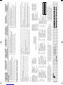
CE - DECLARATION-OF-CONFORMITY
CE - KONFORMITÄTSERKLÄRUNG
CE - DECLARATION-DE-CONFORMITE
CE - CONFORMITEITSVERKLARING
CE - DECLARACION-DE-CONFORMIDAD
CE - DICHIARAZIONE-DI-CONFORMITA
CE - ¢H§ø™H ™YMMOPºø™H™
CE - DECLARAÇÃO-DE-CONFORMIDADE
СЕ - ЗАЯВЛЕНИЕ-О-СООТВЕТСТВИИ
CE - OPFYLDELSESERKLÆRING
CE - FÖRSÄKRAN-OM-ÖVERENSTÄMMELSE
CE - ERKLÆRING OM-SAMSVAR
CE - ILMOITUS-YHDENMUKAISUUDESTA
CE - PROHLÁŠENÍ-O-SHODĚ
CE - IZJAVA-O-USKLAĐENOSTI
CE - MEGFELELŐSÉGI-NYILATKOZAT
CE - DEKLARACJA-ZGODNOŚCI
CE - DECLARAŢIE-DE-CONFORMITATE
CE - IZJAVA O SKLADNOSTI
CE - VASTAVUSDEKLARATSIOON
CE - ДЕКЛАРАЦИЯ-ЗА-СЪОТВЕТСТВИЕ
CE - ATITIKTIES-DEKLARACIJA
CE - ATBILSTĪBAS-DEKLARĀCIJA
CE - VYHLÁSENIE-ZHODY
CE - UYUMLULUK-BİLDİRİSİ
01 are in conformity with the following standard(s) or other normative document(s), provided that these are used in accordance with our
instructions:
02 der/den folgenden Norm(en) oder einem anderen Normdokument oder -dokumenten entspricht/entsprechen, unter der Voraussetzung,
daß sie gemäß unseren Anweisungen eingesetzt werden:
03 sont conformes à la/aux norme(s) ou autre(s) document(s) normatif(s), pour autant qu'ils soient utilisés conformément à nos instructions:
04 conform de volgende norm(en) of één of meer andere bindende documenten zijn, op voorwaarde dat ze worden gebruikt overeenkomstig
onze instructies:
05 están en conformidad con la(s) siguiente(s) norma(s) u otro(s) documento(s) normativo(s), siempre que sean utilizados de acuerdo con
nuestras instrucciones:
06 sono conformi al(i) seguente(i) standard(s) o altro(i) documento(i) a carattere normativo, a patto che vengano usati in conformità alle
nostre istruzioni:
07 Â›Ó·È Û‡Ìʈӷ Ì ÙÔ(·) ·ÎfiÏÔ˘ıÔ(·) ÚfiÙ˘Ô(·) ‹ ¿ÏÏÔ ¤ÁÁÚ·ÊÔ(·) ηÓÔÓÈÛÌÒÓ, ˘fi ÙËÓ ÚÔ¸fiıÂÛË fiÙÈ ¯ÚËÛÈÌÔÔÈÔ‡ÓÙ·È
Û‡Ìʈӷ Ì ÙȘ Ô‰ËÁ›Â˜ Ì·˜:
08 estão em conformidade com a(s) seguinte(s) norma(s) ou outro(s) documento(s) normativo(s), desde que estes sejam utilizados de
acordo com as nossas instruções:
09 соответствуют следующим стандартам или другим нормативным документам, при условии их использования согласно нашим
инструкциям:
10 overholder følgende standard(er) eller andet/andre retningsgivende dokument(er), forudsat at disse anvendes i henhold til vore
instrukser:
11 respektive utrustning är utförd i överensstämmelse med och följer följande standard(er) eller andra normgivande dokument, under
förutsättning att användning sker i överensstämmelse med våra instruktioner:
12 respektive utstyr er i overensstemmelse med følgende standard(er) eller andre normgivende dokument(er), under forutssetning av at
disse brukes i henhold til våre instrukser:
13 vastaavat seuraavien standardien ja muiden ohjeellisten dokumenttien vaatimuksia edellyttäen, että niitä käytetään ohjeidemme
mukaisesti:
14 za předpokladu, že jsou využívány v souladu s našimi pokyny, odpovídají následujícím normám nebo normativním dokumentům:
15 u skladu sa slijedećim standardom(ima) ili drugim normativnim dokumentom(ima), uz uvjet da se oni koriste u skladu s našim uputama:
16 megfelelnek az alábbi szabvány(ok)nak vagy egyéb irányadó dokumentum(ok)nak, ha azokat előírás szerint használják:
17 spełniają wymogi następujących norm i innych dokumentów normalizacyjnych, pod warunkiem że używane są zgodnie z naszymi
instrukcjami:
18 sunt în conformitate cu următorul (următoarele) standard(e) sau alt(e) document(e) normativ(e), cu condiţia ca acestea să fie utilizate în
conformitate cu instrucţiunile noastre
19 skladni z naslednjimi standardi in drugimi normativi, pod pogojem, da se uporabljajo v skladu z našimi navodili:
20 on vastavuses järgmis(t)e standardi(te)ga või teiste normatiivsete dokumentidega, kui neid kasutatakse vastavalt meie juhenditele:
21 съответстват на следните стандарти или други нормативни документи, при условие, че се използват съгласно нашите
инструкции:
22 atitinka žemiau nurodytus standartus ir (arba) kitus norminius dokumentus su sąlyga, kad yra naudojami pagal mūsų nurodymus:
23 tad, ja lietoti atbilstoši ražotāja norādījumiem, atbilst sekojošiem standartiem un citiem normatīviem dokumentiem:
24 sú v zhode s nasledovnou(ými) normou(ami) alebo iným(i) normatívnym(i) dokumentom(ami), za predpokladu, že sa používajú v súlade
s našim návodom:
25 ürünün, talimatlarımıza göre kullanılması koşuluyla aşağıdaki standartlar ve norm belirten belgelerle uyumludur:
01 Directives, as amended.
02 Direktiven, gemäß Änderung.
03 Directives, telles que modifiées.
04 Richtlijnen, zoals geamendeerd.
05 Directivas, según lo enmendado.
06 Direttive, come da modifica.
07 √‰ËÁÈÒv, fiˆ˜ ¤¯Ô˘Ó ÙÚÔÔÔÈËı›.
08 Directivas, conforme alteração em.
09 Директив со всеми поправками.
10 Direktiver, med senere ændringer.
11 Direktiv, med företagna ändringar.
12 Direktiver, med foretatte endringer.
13
Direktiivejä, sellaisina kuin ne ovat muutettuina.
14 v platném znění.
15 Smjernice, kako je izmijenjeno.
16
irányelv(ek) és módosításaik rendelkezéseit.
17 z późniejszymi poprawkami.
18 Directivelor, cu amendamentele respective.
19 Direktive z vsemi spremembami.
20 Direktiivid koos muudatustega.
21 Директиви, с техните изменения.
22 Direktyvose su papildymais.
23 Direktīvās un to papildinājumos.
24 Smernice, v platnom znení.
25 Değiştirilmiş halleriyle Yönetmelikler.
01 following the provisions of:
02 gemäß den Vorschriften der:
03 conformément aux stipulations des:
04 overeenkomstig de bepalingen van:
05 siguiendo las disposiciones de:
06 secondo le prescrizioni per:
07 Ì ًÚËÛË Ùˆv ‰È·Ù¿Íˆv Ùˆv:
08 de acordo com o previsto em:
09 в соответствии с положениями:
10 under iagttagelse af bestemmelserne i:
11 enligt villkoren i:
12 gitt i henhold til bestemmelsene i:
13 noudattaen määräyksiä:
14 za dodržení ustanovení předpisu:
15 prema odredbama:
16 követi a(z):
17 zgodnie z postanowieniami Dyrektyw:
18 în urma prevederilor:
19 ob upoštevanju določb:
20 vastavalt nõuetele:
21 следвайки клаузите на:
22 laikantis nuostatų, pateikiamų:
23 ievērojot prasības, kas noteiktas:
24 održiavajúc ustanovenia:
25 bunun koşullarına uygun olarak:
01 Note * as set out in <A> and judged positively by <B>
according to the Certificate <C>.
02 Hinweis * wie in der <A> aufgeführt und von <B> positiv
beurteilt gemäß Zertifikat <C>.
03 Remarque * tel que défini dans <A> et évalué positivement par
<B> conformément au Certificat <C>.
04 Bemerk * zoals vermeld in <A> en positief beoordeeld door
<B> overeenkomstig Certificaat <C>.
05 Nota *como se establece en <A> y es valorado
positivamente por <B> de acuerdo con el
Certificado <C>.
06 Nota * delineato nel <A> e giudicato positivamente
da <B> secondo il Certificato <C>.
07 ™ËÌ›ˆÛË * fiˆ˜ ηıÔÚ›˙ÂÙ·È ÛÙÔ <A> Î·È ÎÚ›ÓÂÙ·È ıÂÙÈο
·fi ÙÔ <B> Û‡Ìʈӷ Ì ÙÔ ¶ÈÛÙÔÔÈËÙÈÎfi <C>.
08 Nota *tal como estabelecido em <A> e com o parecer
positivo de <B> de acordo com o Certificado <C>.
09 Примечание * как указано в <A> и в соответствии с
положительным решением <B> согласно
Свидетельству <C>.
10 Bemærk * som anført i <A> og positivt vurderet af <B> i
henhold til Certifikat <C>.
11 Information * enligt <A> och godkänts av <B> enligt
Certifikatet <C>.
12 Merk * som det fremkommer i <A> og gjennom positiv
bedømmelse av <B> ifølge Sertifikat <C>.
13 Huom * jotka on esitetty asiakirjassa <A> ja jotka <B> on
hyväksynyt Sertifikaatin <C> mukaisesti.
14 Poznámka * jak bylo uvedeno v <A> a pozitivně zjištěno <B> v
souladu s osvědčením <C>.
15 Napomena * kako je izloženo u <A> i pozitivno ocijenjeno od
strane <B> prema Certifikatu <C>.
16 Megjegyzés * a(z) <A> alapján, a(z) <B> igazolta a megfelelést,
a(z) <C> tanúsítvány szerint.
17 Uwaga * zgodnie z dokumentacją <A>, pozytywną opinią
<B> i Świadectwem <C>.
18 Notă * aşa cum este stabilit în <A> şi apreciat pozitiv
de <B> în conformitate cu Certificatul <C>.
19 Opomba * kot je določeno v <A> in odobreno s strani <B> v
skladu s certifikatom <C>.
20 Märkus *nagu on näidatud dokumendis <A> ja heaks
kiidetud <B> järgi vastavalt sertifikaadile <C>.
21 Забележка * както е изложено в <A> и оценено
положително от <B> съгласно
Cертификата <C>.
22 Pastaba * kaip nustatyta <A> ir kaip teigiamai nuspręsta <B>
pagal Sertifikatą <C>.
23 Piezīmes * kā norādīts <A> un atbilstoši <B> pozitīvajam
vērtējumam saskaņā ar sertifikātu <C>.
24 Poznámka * ako bolo uvedené v <A> a pozitívne zistené <B> v
súlade s osvedčením <C>.
25
Not
*
<A>‘da belirtildiği gibi ve <C> Sertifikasına
göre <B> tarafından olumlu olarak
değerlendirildiği gibi.
<A> DAIKIN.TCF.028/10-2010
<B> KEMA (NB0344)
<C> 2134252.0551-QUA/EMC
01
a
declares under its sole responsibility that the air conditioning models to which this declaration relates:
02
d
erklärt auf seine alleinige Verantwortung daß die Modelle der Klimageräte für die diese Er klärung bestimmt ist:
03
f
déclare sous sa seule responsabilité que les appareils d'air conditionné visés par la présente déclaration:
04
l
verklaart hierbij op eigen exclusieve verantwoordelijkheid dat de airconditioning units waarop deze verklaring betrekking heeft:
05
e
declara baja su única responsabilidad que los modelos de aire acondicionado a los cuales hace
referencia la
declaración:
06
i
dichiara sotto sua responsabilità che i condizionatori modello a cui è riferita questa dichiarazione:
07
g
‰ËÏÒÓÂÈ Ì ·ÔÎÏÂÈÛÙÈ΋ Ù˘ ¢ı‡ÓË fiÙÈ Ù· ÌÔÓ٤Ϸ ÙˆÓ ÎÏÈÌ·ÙÈÛÙÈÎÒÓ Û˘Û΢ÒÓ ÛÙ· ÔÔ›· ·Ó·Ê¤ÚÂÙ·È Ë ·ÚÔ‡Û· ‰‹ÏˆÛË:
08
p
declara sob sua exclusiva responsabilidade que os modelos de ar condicionado a que esta declaração se refere:
09
u
заявляет, исключительно под свою ответственность, что модели кондиционеров воздуха, к которым относится настоящее заявление:
10
q
erklærer under eneansvar, at klimaanlægmodellerne, som denne deklaration vedrører:
11
s
deklarerar i egenskap av huvudansvarig, att luftkonditioneringsmodellerna som berörs av denna deklaration innebär att:
12
n
erklærer et fullstendig ansvar for at de luftkondisjoneringsmodeller som berøres av denne deklarasjon innebærer at:
13
j
ilmoittaa yksinomaan omalla vastuullaan, että tämän ilmoituksen tarkoittamat ilmastointilaitteiden mallit:
14
c
prohlašuje ve své plné odpovědnosti, že modely klimatizace, k nimž se toto prohlášení vztahuje:
15
y
izjavljuje pod isključivo vlastitom odgovornošću da su modeli klima uređaja na koje se ova izjava odnosi:
16
h
teljes felelőssége tudatában kijelenti, hogy a klímaberendezés modellek, melyekre e nyilatkozat vonatkozik:
17
m
deklaruje na własną i wyłączną odpowiedzialność, że modele klimatyzatorów, których dotyczy niniejsza deklaracja:
18
r
declară pe proprie răspundere că aparatele de aer condiţionat la care se referă această declaraţie:
19
o
z vso odgovornostjo izjavlja, da so modeli klimatskih naprav, na katere se izjava nanaša:
20
x
kinnitab oma täielikul vastutusel, et käesoleva deklaratsiooni alla kuuluvad kliimaseadmete mudelid:
21
b
декларира на своя отговорност, че моделите климатична инсталация, за които се отнася тази декларация:
22
t
visiška savo atsakomybe skelbia, kad oro kondicionavimo prietaisų modeliai, kuriems yra taikoma ši deklaracija:
23
v
ar pilnu atbildību apliecina, ka tālāk uzskaitīto modeĮu gaisa kondicionētāji, uz kuriem attiecas šī deklarācija:
24
k
vyhlasuje na vlastnú zodpovednosť, že tieto klimatizačné modely, na ktoré sa vzťahuje toto vyhlásenie:
25
w
tamamen kendi sorumluluğunda olmak üzere bu bildirinin ilgili olduğu klima modellerinin aşağıdaki gibi olduğunu beyan eder:
EN60335-2-40,
3PW66183-1
Jean-Pierre Beuselinck
General Manager
Ostend, 2nd of November 2010
01
**
Daikin Europe N.V. is authorised to compile the Technical Construction File.
02
**
Daikin Europe N.V. hat die Berechtigung die Technische Konstruktionsakte zusammenzustellen.
03
**
Daikin Europe N.V. est autorisé à compiler le Dossier de Construction Technique.
04
**
Daikin Europe N.V. is bevoegd om het Technisch Constructiedossier samen te stellen.
05
**
Daikin Europe N.V. está autorizado a compilar el Archivo de Construcción Técnica.
06
**
Daikin Europe N.V. è autorizzata a redigere il File Tecnico di Costruzione.
07
**
∏ Daikin Europe N.V. Â›Ó·È ÂÍÔ˘ÛÈÔ‰ÔÙË̤ÓË Ó· Û˘ÓÙ¿ÍÂÈ ÙÔÓ ∆¯ÓÈÎfi Ê¿ÎÂÏÔ Î·Ù·Û΢‹˜.
08
**
A Daikin Europe N.V. está autorizada a compilar a documentação técnica de fabrico.
09
**
Компания Daikin Europe N.V. уполномочена составить Комплект технической документации.
10
**
Daikin Europe N.V. er autoriseret til at udarbejde de tekniske konstruktionsdata.
11
**
Daikin Europe N.V. är bemyndigade att sammanställa den tekniska konstruktionsfilen.
12
**
Daikin Europe N.V. har tillatelse til å kompilere den Tekniske konstruksjonsfilen.
13
**
Daikin Europe N.V. on valtuutettu laatimaan Teknisen asiakirjan.
14
**
Společnost Daikin Europe N.V. má oprávnění ke kompilaci souboru technické konstrukce.
15
**
Daikin Europe N.V. je ovlašten za izradu Datoteke o tehničkoj konstrukciji.
16
**
A Daikin Europe N.V. jogosult a műszaki konstrukciós dokumentáció összeállítására.
17
**
Daikin Europe N.V. ma upoważnienie do zbierania i opracowywania dokumentacji konstrukcyjnej.
18
**
Daikin Europe N.V. este autorizat să compileze Dosarul tehnic de construcţie.
19
**
Daikin Europe N.V. je pooblaščen za sestavo datoteke s tehnično mapo.
20
**
Daikin Europe N.V. on volitatud koostama tehnilist dokumentatsiooni.
21
**
Daikin Europe N.V. е оторизирана да състави Акта за техническа конструкция.
22
**
Daikin Europe N.V. yra įgaliota sudaryti šį techninės konstrukcijos failą.
23
**
Daikin Europe N.V. ir autorizēts sastādīt tehnisko dokumentāciju.
24
**
Spoločnosť Daikin Europe N.V. je oprávnená vytvoriť súbor technickej konštrukcie.
25
**
Daikin Europe N.V. Teknik Yapı Dosyasını derlemeye yetkilidir.
Low Voltage 2006/95/EC
Machinery 2006/42/EC
Electromagnetic Compatibility 2004/108/EC
**
*
FWF02B7TV1B*, FWF03B7TV1B*, FWF04B7TV1B*, FWF05B7TV1B*,
FWF02B7FV1B*, FWF03B7FV1B*, FWF04B7FV1B*, FWF05B7FV1B*,
* = , , 1, 2, 3, ..., 9
3PW66183-1_FWF_B7T+FV1B.fm Page 1 Friday, October 1, 2010 2:47 PM

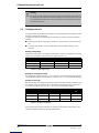
Table of contents
1 Introduction 1
1.1 About fan coil units 1
1.2 About this fan coil unit 1
1.3 About this document 2
1.3.1 Meaning of warnings and symbols 2
2 Precautions for installation 3
3 Prepare the installation of the fan coil unit 4
3.1 Check that you have all optional equipment 4
3.2 Verify the appropriate installation location 5
3.3 Prepare the installation space 6
3.4 Prepare the water piping work 6
3.5 Prepare the electrical wiring work 7
3.6 Prepare the installation of optional equipment 9
4 Install the fan coil unit 10
4.1 Unpack the unit 10
4.2 Check if all accessories are included 10
4.3 Prepare the ceiling opening 11
4.4 Fix the unit 12
4.5 Perform the water piping work 14
4.5.1 Connect the water pipes 14
4.5.2 Insulate the water pipes 15
4.5.3 Fill the water circuit 16
4.6 Connect the electrical wiring 16
4.6.1 Connect the power supply 20
4.6.2 Connect the remote controller and unit transmission wiring 21
4.6.3 Close the control box 21
4.7 Perform the drain piping work 21
4.7.1 Install the drain piping in the building 21
4.7.2 Connect the drain piping to the unit 23
4.7.3 Test the drain piping 24
4.8 Install optional equipment 25


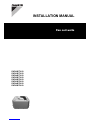
FWF
Fan coil units
4PW64524-1 – 09.2010
Installation manual
1
1 Introduction
1Introduction
About fan coil units
1.1 About fan coil units
A fan coil unit provides heating and cooling to individual spaces. It creates a comfortable
environment in both commercial and residential applications. Fan coil units are widely used
for the air conditioning of offices, hotels and houses.
The main components of fan coil units are:
■a fan,
■a coil (heat exchanger).
The heat exchanger receives hot or cold water from a heating or cooling source. The fan
spreads the heat or coolness in order to condition the space.
DAIKIN offers a wide range of fan coil units for both concealed and exposed applications.
Contact your DAIKIN dealer for a list of related products.
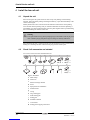
About this fan coil unit
1.2 About this fan coil unit
The model identification code means:
FW
F
02
B
7
T
V1
B
Water fan
coil unit
Subclass:
Cassette
F: 2x2
Tot al
cooling
capacity
(kW)
Major
model
change
Minor
model
change
Coil type:
T: 2-pipe
F: 4-pipe
1 phase /
50 Hz /
220-240 V
Produced
in Europe
The following models are available:
■FWF02-03-04-05B7TV1B
2-pipe fan coil units have one supply and one return pipe. The supply pipe can supply
either hot or cold water to the unit.
■FWF02-03-04-05B7FV1B
4-pipe fan coil units have two supply pipes and two return pipes. This allows either hot
or cold water to enter the unit which makes it possible to heat and cool different areas of
a building at the same time. Use this type if you have a separate source for cooling and
for heating.
About this document

Installation manual
2
FWF
Fan coil units
4PW64524-1 – 09.2010
1 Introduction
1.3 About this document
This document is an installation manual. It is intended for the installer of this product. It
describes the procedures for installing, commissioning and maintaining the unit, and it will
provide help if problems occur. Carefully read the relevant parts of the manual.
How to get the manual?
■A printed version of the manual is delivered with the unit.
■Contact your local DAIKIN dealer for an electronic version of the manual.
For detailed instructions about how to install and operate the associated products and/or
optional equipment, refer to the relevant catalogues, technical literature or product manuals
for those products.
The original documentation is written in English. All other languages are translations of the
original documentation.
About this document
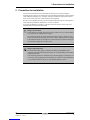
1.3.1 Meaning of warnings and symbols
Warnings in this manual are classified according to their severity and probability of
happening.
Danger: Indicates an imminently hazardous situation which, if not avoided, will
result in death or serious injury.
Warning: Indicates a potentially hazardous situation which, if not avoided, could
result in death or serious injury.
Caution: Indicates a potentially hazardous situation which, if not avoided, may
result in minor or moderate injury.
Notice: Indicates situations that may result in damage to equipment or property.
Information: This symbol identifies useful information, but no hazardous situation
warnings.
Some types of danger are represented by special symbols:
Electric current
Danger of burning or scalding

FWF
Fan coil units
4PW64524-1 – 09.2010
Installation manual
3
2 Precautions for installation
2 Precautions for installation
All instructions described in this manual shall be carried out by a licensed installer.
Install the unit according to the instructions in the included documentation and the manuals
of the additional equipment (e.g. controller). Improper installation could result in electric
shock, short-circuit, leaks, fire or other damage to the equipment.
Be sure to wear adequate personal protection equipment (protection gloves, safety glasses)
when performing installation, maintenance or service to the unit.
If not sure of installation procedures or operation of the unit, always contact your local
DAIKIN dealer for advice and information.
Danger: electric shock
Switch off all power supply before removing the control box cover or before making
any connections or touching electrical parts.
To avoid electric shock, be sure to disconnect the power supply 1 minute or more
before servicing the electrical parts. Even after 1 minute, always measure the voltage
at the terminals of main circuit capacitors or electrical parts and, before touching, be
sure that those voltages are 50 V DC or less.
Danger: high temperature
Do not touch the water piping or internal parts during and immediately after
operation. The piping and internal parts may be hot or cold depending on the working
condition of the unit.
Your hand may get burned or frostbitten if you touch the piping or internal parts. To
avoid injury, give the piping and internal parts time to return to normal temperature
or, if you must touch them, be sure to wear adequate protective gloves.

Installation manual
4
FWF
Fan coil units
4PW64524-1 – 09.2010
3 Prepare the installation of the fan coil unit
3 Prepare the installation of the fan coil unit
Check that you have all optional equipment
3.1 Check that you have all optional equipment
Decoration panel
Identification code
Description
Decoration panel
BYFQ60B
Decoration panel for the fan
coil unit.
Panel spacer
KDBQ44B60
Decorative spacer to fill the
gap between panel and unit
when the height of the
suspended ceiling is too
small.
Controllers
Identification code
Description
Electronic remote controller -
wireless (cooling and
heating)
BRC7E530
Wireless remote controller to
control each fan coil unit
independently with cooling
and heating functionality.
Electronic remote controller -
wireless (cooling only)
BRC7E531
Wireless remote controller to
control each fan coil unit
independently with cooling
functionality only.
Electronic remote controller -
wired
BRC315D7
Wired remote controller to
control each fan coil unit with
cooling and heating
functionality.
Central remote controller
DCS302CA51
Remote controller for
centralized control of all
connected units.
Intelligent touch controller
DCS601C51C
Advanced remote controller
for centralized control of all
connected units.
Unified ON/OFF controller
DCS301BA51
Remote controller to switch
all connected units ON or
OFF.
Air handling options
Identification code
Description
Sealing member of air
discharge outlet
KDBH44BA60
Blocking parts to close one or
more air outlets of the fan
coil unit.
Long-life replacement filter
KAFQ441BA60
High quality filter.
Fresh air intake kit
KDDQ44XA60
Kit which can be connected
to the ventilation system in
order to supply fresh air to
the fan coil unit.
Sensor
Identification code
Description
Remote sensor
KRCS01-1
Replacement sensor to
measure temperature
remotely from a location
other than that in which the
controller is installed.

Timer
Identification code
Description
Schedule timer
DST301BA51
Controller with schedule
timing functionality.
Valv es
Identification code
Description
2-way valve (ON/OFF type)
EKMV2C09B7
Electronic 2-way valve to
control the water supply.
3-way valve (ON/OFF type)
EKMV3C09B7
Electronic 3-way valve to
control the water supply.
Electronic circuits
Identification code
Description
Valve control PCB
EKRP1C11
Mandatory electronic circuit
when 2-way or 3-way valve
is used.
Optional PCB for MOD-bus
connection
EKFCMBCB7
Electronic circuit with MOD-
bus interface connections.
Wiring adaptor for electrical
appendices
KRP4A(A)53
KRP2A52
Electronic circuit with
additional connections for
external input/output signals.
Remote “ON/OFF” and
“Forced OFF” kit
EKROROA
Connection to control the
ON/OFF operation remotely.
FWF
Fan coil units
4PW64524-1 – 09.2010
Installation manual
5
3 Prepare the installation of the fan coil unit
Verify the appropriate installation loca tion
3.2 Verify the appropriate installation location
When selecting the installation location, take into account the instructions as mentioned in
the following paragraphs of this chapter.
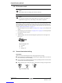
Select an installation location where the following conditions are fulfilled:
■the space around the unit is adequate for maintenance and servicing. See figure “Space
required for installation” on page 6.
■the space around the unit allows sufficient air circulation and air distribution. See figure
“Space required for installation” on page 6.
■the unit may be installed on ceilings up to 3.5 m. However, it becomes necessary to make
field settings using the remote controller when installing the unit at a height over 2.7 m.
Install the unit where the height of the decoration panel is more than 2.5 m to avoid
accidental touching.
■the air passage is not blocked.
■the condensate water can be properly drained.
■the installation location is frost-free.
■the unit can be installed horizontally.

Installation manual
6
FWF
Fan coil units
4PW64524-1 – 09.2010
3 Prepare the installation of the fan coil unit
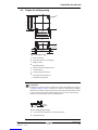
■the unit must be installed as far away as possible from fluorescent lights or other sources
that possibly interfere with the signal of wireless remote controllers.
aa
b
≥2500
≥1500
≥295
*
≥1500
*
≥1500
Fig. 3.1: Space required for installation
a
Air outlet
b
Air inlet
Information
Leave 200 mm or more space where marked with *, on sides where the air outlet is
closed.
Refer to figure “Space required for installation” on page 6.
Information
The equipment is not intended for use in a potentially explosive atmosphere.
Prepare the installation space
3.3 Prepare the installation space
■When preparing the installation space, use the paper pattern for installation which is
delivered with the unit. More information on how to prepare the ceiling opening can be
found in chapter “Prepare the ceiling opening” on page 11.
■When the conditions in the built-in space are exceeding 30°C and exceeding a relative
humidity of 80%, or when fresh air is inducted into the ceiling, an additional insulation
is required on the outside of the unit (minimum 10 mm thickness polyethylene foam).
Prepare the water piping work
3.4 Prepare the water piping work
The unit is equipped with a water inlet and water outlet for connection to a water circuit. The
water circuit must be provided by an installer and must comply with the applicable
legislation.
Notice
The unit is only to be used in a closed water system. Application in an open water
circuit can lead to excessive corrosion of the water piping.
Before performing the water piping work, check the following points:
■the maximum water pressure is 10 bar,
■the minimum water temperature is 5°C,
■the maximum water temperature is 70°C,
■be sure to install components in the field piping that can withstand the water pressure and
temperature,

FWF
Fan coil units
4PW64524-1 – 09.2010
Installation manual
7
3 Prepare the installation of the fan coil unit
■provide adequate safeguards in the water circuit to be sure that the water pressure will
never exceed the maximum allowable working pressure,
■provide a proper drain for the pressure relief valve (if installed) to avoid any water
coming into contact with electrical parts,
■be sure that the water flow rates are according to the table below,
Minimum water speed
(l/min.)
Maximum water speed
(l/min.)
FWF02-05B7TV1B 2.7 18
FWF02B7FV1B 2.7 10.8
FWF03-05B7FV1B 2.7 14.4
Table 3.1: Maximum and minimum water flow
■provide shut-off valves at the unit so that normal servicing can be accomplished without
draining the system,
■provide drain taps at all low points of the system to permit complete drainage of the
circuit during maintenance or service to the unit,
■provide air purge valves at all high points of the system. The valves shall be located at
points which are easily accessible for servicing. A manual air purge valve is mounted
onto the unit,
■always use materials which are compatible with the water and 40% volume glycol,
■select piping diameter in relation to required water flow and available ESP (External
Static Pressure) of the pump.
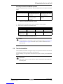
Prepare the electrical wiring work
3.5 Prepare the electrical wiring work
The unit must be connected to the power supply. All field wiring and components must be
installed by an installer and must comply with the applicable legislation.
Warning
A main switch or other means for disconnection, having a contact separation in all
poles, must be incorporated in the fixed wiring in accordance with the applicable
legislation.
Before connecting the electrical wiring, check the following points:
■use copper wires only,
■all field wiring must be carried out in accordance with the wiring diagram delivered with
the unit,
■never squeeze bundled cables and be sure that cables do not come in contact with the
piping and sharp edges. Be sure no external pressure is applied to the terminal
connections,
■be sure to establish an earth. Do not earth the unit to a utility pipe, surge absorber, or
telephone earth. Incomplete earth may cause electrical shock,
■be sure to install an earth leakage detector in accordance with the applicable legislation.
Failure to do so may cause electric shock or fire. The earth leakage detector is a field
supplied part,
■be sure to install the required fuses or circuit breakers. The fuse or circuit breakers are
field supplied parts.

Information
The equipment described in this manual may cause electronic noise generated from
radio-frequency energy. The equipment complies to specifications that are designed
to provide reasonable protection against such interference. However, there is no
guarantee that interference will not occur in a particular installation.
It is therefore recommended to install the equipment and electric wires keeping
proper distances away from stereo equipment, personal computers, etc.
In extreme circumstances a distance of 3 m or more is required.
Installation manual
8
FWF
Fan coil units
4PW64524-1 – 09.2010
3 Prepare the installation of the fan coil unit
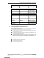
Electrical characteristics
Model
FWF
Phase
1N~
Frequency (Hz)
50
Voltage range (V)
220-240
Voltage tolerance (V)
±10%
Maximum running current (A)
0.9
Overcurrent fuse (A) (field supply)
16 (a)
Table 3.2: Electrical characteristics
(a) In case of common power supply to more than one unit (as illustrated in figure “Group control or use with 2
remote controllers” on page 19), keep total current of interconnection wiring between units less than 12 A.
Branch the line outside the terminal block of the unit in accordance with electrical equipment standards, when
using two power wires of a gauge greater than 2 mm². The branch must be sheathed in order to provide an equal
or greater degree of insulation as power supply wiring itself.
Specifications for field wiring
Wire Size (mm²) Length
Power supply wiring
H05VV-U3G (a),(b) According to the
applicable
legislation. Max. 4.0
—
Remote controller
and unit transmission
wiring
Sheathed wire
2 conductors(c)
0.75-1.25
Max. 500 m(d)
Table 3.3: Field wiring specifications
(a) Only in case of protected pipes. Use H07RN-F in case of no protection.
(b) Run electrical wiring through a conduit to protect against external forces.
(c) Use double insulation wire for remote controller (sheath thickness: ≥1 mm) or run wires through a wall or
conduit so that the user cannot come in contact with them.
(d) This length is the total extended length in the system in case of group control. See figure “Group control or use
with 2 remote controllers” on page 19.
Prepare the installation of optional equipment

FWF
Fan coil units
4PW64524-1 – 09.2010
Installation manual
9
3 Prepare the installation of the fan coil unit
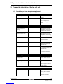
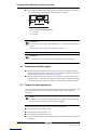
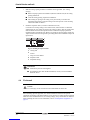
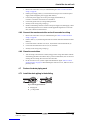
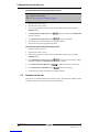
3.6 Prepare the installation of optional equipment
Air flow directions
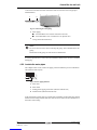
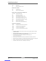
For this unit you can select different air flow directions. It is necessary to purchase an optional
blocking pad kit to limit the air discharge to 2, 3 or 4 (closed corners) directions.
Select the air flow directions best suited for the room and point of installation. For air
discharge in 2 or 3 directions, it is necessary to make field settings by means of the remote
controller and to close the air outlet(s) as illustrated in the figure below. ( air flow
direction)
abc
Fig. 3.2: Air flow directions
a
Air discharge in 4 directions
b
Air discharge in 3 directions
c
Air discharge in 2 directions
Information
Air flow directions as shown merely serve as examples of possible air flow
directions.
For other preparations related to the installation of optional equipment refer to “Install
optional equipment” on page 25.

Installation manual
10
FWF
Fan coil units
4PW64524-1 – 09.2010
4 Install the fan coil unit
4 Install the fan coil unit
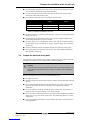
Unpack the unit
4.1 Unpack the unit
When receiving the unit, please check its state. Verify if any damage occurred during
transport. If the unit and/or packing are damaged at delivery, report this immediately to the
carrier’s claims agent.
Identify model and version of the unit from the indications stated on the carton packing.
Leave the unit inside its packing until you reach the installation site. Where unpacking is
unavoidable, use a sling of soft material or protective plates together with a rope when lifting,
this to avoid damage or scratches to the unit.
Warning
Tear apart and throw away plastic packaging bags so that children will not play with
them. Children playing with plastic bags face danger of death by suffocation.
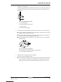
When unpacking the unit or when moving the unit after unpacking, be sure to lift the unit by
holding on to the hanger bracket without exerting any pressure on other parts.
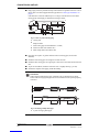
Check if all accessories are included
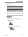
4.2 Check if all accessories are included
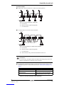
An overview of the accessories included in the box:
a
1x
b
1x
c
8x
d
4x
e
1x
1x
h
1x
i
2x
j
1x
k
1x
l
f
FWF_T 2x
FWF_F 4x
g
FWF_T 2x
FWF_F 4x
m
FWF_T 2x
FWF_F 4x
Fig. 4.1: Accessories
a
Metal clamp
b
Drain hose
c
Washer for hanger bracket
d
Screw
e
Paper pattern for installation
f
Insulation tube
g
O-ring
h
Large sealing pad
i
Small sealing pad
j
Sealing pad
k
Installation manual
l
User manual
m
Sealing pad for piping connections
Prepare the ceiling opening

FWF
Fan coil units
4PW64524-1 – 09.2010
Installation manual
11
4 Install the fan coil unit
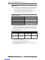
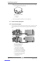
4.3 Prepare the ceiling opening
533
575
585~660
*
585
585~660
*
700
20
45
20
45
533
575
585~660
*
700
a
c
e
f
g
g
h
h
g
f
e
b
d
i
Fig. 4.2: Opening in ceiling
a
Water inlet/outlet
b
Suspension bolt (x4) (field supply)
c
Hanger bracket
d
Suspended ceiling
e
Distance between suspension bolts
f
Unit dimensions
g
Ceiling opening dimensions
h
Decoration panel dimensions
i
Suspended ceiling frame
Information
Installation is possible with a ceiling dimension of 660 mm (marked with * in figure
“Opening in ceiling” on page 11). However, to achieve a ceiling-panel overlapping
dimension of 20 mm, the spacing between the ceiling and the unit should be 45 mm
or less. If the spacing between ceiling and the unit is over 45 mm, attach sealing
material or recovered ceiling in the area marked below.
≤45
b a
Fig. 4.3: Ceiling spacing too large
a
Area to fit sealing material or recovered ceiling into
b
Suspended ceiling

Installation manual
12
FWF
Fan coil units
4PW64524-1 – 09.2010
4 Install the fan coil unit
1 Make the ceiling opening needed for installation where applicable. (For existing
ceilings.)
■Refer to the paper pattern for installation (delivered with the unit) for the ceiling
opening dimensions.
■Create the ceiling opening required for installation.
■After making an opening in the ceiling, it may be necessary to reinforce the
suspended ceiling frame to keep the ceiling level and to prevent it from vibrating.
Consult the builder for details.
2 Install the suspension bolts. (Use either a M8~M10 size bolt.)
Use anchors for existing ceilings, and a sunken insert, sunken anchors or other field
supplied parts for new ceilings to reinforce the ceiling in order to bear the weight of the
unit. The distance between the suspension bolts is marked on the paper pattern for
installation (delivered with the unit). Refer to it to check for points requiring reinforcing.
Adjust clearance from the ceiling before proceeding further. See installation example in
figure below:
c
b
d
e
a
50 - 100
Fig. 4.4: Installing the suspension bolts
a
Ceiling slab
b
Anchor
c
Long nut or turn-buckle
d
Suspension bolt
e
Suspended ceiling
Information
■All the above parts are field supplied.
■For installation other than standard installation, contact your local DAIKIN
dealer for advice.
Fix the unit
4.4 Fix the unit
Caution
To avoid injury, do not touch the air inlet or aluminium fins of the unit.
When installing optional equipment, also read the installation manual of the optional
equipment. Depending on the field conditions, it may be easier to install optional equipment
before the unit is installed. However, for existing ceilings, always install fresh air intake kit
before installing the unit. For more information, refer to “Install optional equipment” on
page 25.

FWF
Fan coil units
4PW64524-1 – 09.2010
Installation manual
13
4 Install the fan coil unit
1 Install the unit temporarily.
Attach the hanger bracket to the suspension bolt. Be sure to fix it securely by using a nut
and washer from the upper and lower sides of the hanger bracket as illustrated in the
figure below.
b
a
c
d
Fig. 4.5: Securing the hanger bracket
a
Nut (field supply)
b
Washer (delivered with the unit)
c
Hanger bracket
d
Double nut (field supply)
2 Fix the paper pattern for installation (delivered with the unit). (For new ceilings only.)
a
b
b
■The paper pattern for installation corresponds with the measurements of the ceiling
opening. Consult the builder for details.
■The centre of the ceiling opening is indicated on the paper pattern for installation.
The centre of the unit is indicated on the unit casing.
■Attach the paper pattern for installation to the unit with the screws as illustrated in
the figure below.
Fig. 4.6: Paper pattern for installation
a
Paper pattern for installation (delivered with the unit)
b
Screws (delivered with the unit)
3 Adjust the unit to the right position for installation.
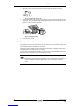
4 Check if the unit is horizontally levelled.
■Do not install the unit tilted. The unit is equipped with a built-in drain pump and float
switch. If the unit is tilted against the direction of the condensate flow (the drain
piping side is raised), the float switch may malfunction and cause water to drip.

b
b
a
Installation manual
14
FWF
Fan coil units
4PW64524-1 – 09.2010
4 Install the fan coil unit
■Check if the unit is levelled at all four corners with a water level or a water-filled
vinyl tube as illustrated in the figure below.
Fig. 4.7: Check if unit is levelled
a
Water level
b
Vinyl tube
5 Remove the paper pattern for installation. (For new ceilings only.)
Perform the water piping work
4.5 Perform the water piping work
Perform the water piping work
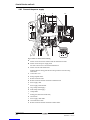
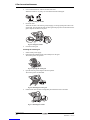
4.5.1 Connect the water pipes
The unit is equipped with water outlet and inlet connections. There is an air purge valve that
is fitted along with the water inlets and outlets for air purging as illustrated in the figure
below.
a
cb
FWF_
T
FWF_
F
FWF_
T
FWF_
F
a
e
g
f b i
i
jh
jd
Fig. 4.8: Water piping connection
a
Drain pipe connection
b
Power supply entry hole
c
Water inlet (3/4" female BSP)
d
Water outlet (3/4" female BSP)
e
Cold water inlet (3/4" female BSP)
f
Cold water outlet (3/4" female BSP)
g
Hot water inlet (3/4" female BSP)
h
Hot water outlet (3/4" female BSP)
i
Transmission wiring entry
j
Air purge valve

FWF
Fan coil units
4PW64524-1 – 09.2010
Installation manual
15
4 Install the fan coil unit
Connect the water inlet and outlet connections of the fan coil unit to the water piping as
illustrated below.
ba
Fig. 4.9: Connecting the water piping
a
Water piping:
■3/4" male BSP in case of direct connection to the unit,
■3/4" female BSP in case of connection to an optional valve.
b
O-ring (delivered with the unit)
Notice
Do not use excessive force when connecting the piping. This could deform the unit
piping.
Deformation of the piping can cause the unit to malfunction.
In case the optional valve is used, refer to the installation manual of the valve kit to install the
field piping.
Perform the water piping work
4.5.2 Insulate the water pipes
The complete water circuit, inclusive all piping, must be insulated to prevent condensation
and reduction of the capacity.
a
b
d
c
c
d
Fig. 4.10: Water piping insulation
a
Water inlet
b
Water outlet
c
Sealing pad for piping connections (delivered with the unit)
d
Insulation tube (delivered with the unit)
If the temperature is higher than 30°C and the relative humidity is higher than 80%, then the
thickness of the sealing materials shall be at least 20 mm in order to avoid condensation on
the surface of the sealing.
Perform the water piping work

Installation manual
16
FWF
Fan coil units
4PW64524-1 – 09.2010
4 Install the fan coil unit
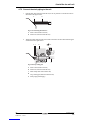
4.5.3 Fill the water circuit
Notice
Water quality must be according to EU directive 98/83 EC.
Notice
Use of glycol is allowed, but the amount shall not exceed 40% of the volume. A
higher amount of glycol may cause damage to the hydraulic components.
During filling, it might not be possible to remove all air in the system. Remaining air can be
removed during the first operating hours of the unit. The air can be removed from the unit
through the manual air purge valve. For the location of the air purge valve on the unit, refer
to figure “Water piping connection” on page 14.
1 Open the air purge valve (refer to figure “Air purge valve” on page 16) by turning the nut
2 times.
2 Push the springy core (refer to figure “Air purge valve” on page 16) to let off superfluous
air from the unit water circuit(s).
3 Close the nut.
4 Additional filling with water afterwards might be required (but never through the air
purge valve).
ab
c
Fig. 4.11: Air purge valve
a
Air purge
b
Nut
c
Springy core
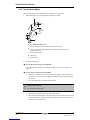
Connect the electrical wiring
4.6 Connect the electrical wiring
Precautions
Observe the notes mentioned below when connecting the electrical wiring.
■Do not connect wires of different gauge to the same power supply terminal. Looseness in
the connection may cause overheating.
■Do not connect wires of different gauge to the same grounding terminal. Looseness in the
connection may deteriorate the protection.
■When connecting wires of the same gauge, connect them according to the figure below.
Fig. 4.12: Terminal wiring
Pagina se încarcă ...
Pagina se încarcă ...
Pagina se încarcă ...
Pagina se încarcă ...
Pagina se încarcă ...
Pagina se încarcă ...
Pagina se încarcă ...
Pagina se încarcă ...
Pagina se încarcă ...
Pagina se încarcă ...
Pagina se încarcă ...
Pagina se încarcă ...
Pagina se încarcă ...
Pagina se încarcă ...
Pagina se încarcă ...
Pagina se încarcă ...
Pagina se încarcă ...
Pagina se încarcă ...
Pagina se încarcă ...
Pagina se încarcă ...
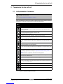
-
 1
1
-
 2
2
-
 3
3
-
 4
4
-
 5
5
-
 6
6
-
 7
7
-
 8
8
-
 9
9
-
 10
10
-
 11
11
-
 12
12
-
 13
13
-
 14
14
-
 15
15
-
 16
16
-
 17
17
-
 18
18
-
 19
19
-
 20
20
-
 21
21
-
 22
22
-
 23
23
-
 24
24
-
 25
25
-
 26
26
-
 27
27
-
 28
28
-
 29
29
-
 30
30
-
 31
31
-
 32
32
-
 33
33
-
 34
34
-
 35
35
-
 36
36
-
 37
37
-
 38
38
-
 39
39
-
 40
40


Daikin FWF02B7FV1B Ghid de instalare
- Tip
- Ghid de instalare
- Acest manual este potrivit și pentru
în alte limbi
Lucrări conexe
-
Daikin R32 Ghid de instalare
-
Daikin EKHWS300D3V3 Ghid de instalare
-
-
-
Daikin R32 Split Series Ghid de instalare
-
Daikin FTXM71M + RXM71M Manualul proprietarului
-
-
-
-
