
Motherboard
PRIME B450-PLUS

ii
E14214
First Edition
May 2018
Copyright © 2018 ASUSTeK COMPUTER INC. All Rights Reserved.
No part of this manual, including the products and software described in it, may be reproduced,
transmitted, transcribed, stored in a retrieval system, or translated into any language in any form or by any
means, except documentation kept by the purchaser for backup purposes, without the express written
permission of ASUSTeK COMPUTER INC. (“ASUS”).
Product warranty or service will not be extended if: (1) the product is repaired, modied or altered, unless
such repair, modication of alteration is authorized in writing by ASUS; or (2) the serial number of the
product is defaced or missing.
ASUS PROVIDES THIS MANUAL “AS IS” WITHOUT WARRANTY OF ANY KIND, EITHER EXPRESS
OR IMPLIED, INCLUDING BUT NOT LIMITED TO THE IMPLIED WARRANTIES OR CONDITIONS OF
MERCHANTABILITY OR FITNESS FOR A PARTICULAR PURPOSE. IN NO EVENT SHALL ASUS, ITS
DIRECTORS, OFFICERS, EMPLOYEES OR AGENTS BE LIABLE FOR ANY INDIRECT, SPECIAL,
INCIDENTAL, OR CONSEQUENTIAL DAMAGES (INCLUDING DAMAGES FOR LOSS OF PROFITS,
LOSS OF BUSINESS, LOSS OF USE OR DATA, INTERRUPTION OF BUSINESS AND THE LIKE),
EVEN IF ASUS HAS BEEN ADVISED OF THE POSSIBILITY OF SUCH DAMAGES ARISING FROM ANY
DEFECT OR ERROR IN THIS MANUAL OR PRODUCT.
SPECIFICATIONS AND INFORMATION CONTAINED IN THIS MANUAL ARE FURNISHED FOR
INFORMATIONAL USE ONLY, AND ARE SUBJECT TO CHANGE AT ANY TIME WITHOUT NOTICE,
AND SHOULD NOT BE CONSTRUED AS A COMMITMENT BY ASUS. ASUS ASSUMES NO
RESPONSIBILITY OR LIABILITY FOR ANY ERRORS OR INACCURACIES THAT MAY APPEAR IN THIS
MANUAL, INCLUDING THE PRODUCTS AND SOFTWARE DESCRIBED IN IT.
Products and corporate names appearing in this manual may or may not be registered trademarks or
copyrights of their respective companies, and are used only for identication or explanation and to the
owners’ benet, without intent to infringe.
Offer to Provide Source Code of Certain Software
This product contains copyrighted software that is licensed under the General Public License (“GPL”),
under the Lesser General Public License Version (“LGPL”) and/or other Free Open Source Software
Licenses. Such software in this product is distributed without any warranty to the extent permitted by the
applicable law. Copies of these licenses are included in this product.
Where the applicable license entitles you to the source code of such software and/or other additional data,
you may obtain it for a period of three years after our last shipment of the product, either
(1) for free by downloading it from http://support.asus.com/download
or
(2) for the cost of reproduction and shipment, which is dependent on the preferred carrier and the location
where you want to have it shipped to, by sending a request to:
ASUSTeK Computer Inc.
Legal Compliance Dept.
15 Li Te Rd.,
Beitou, Taipei 112
Taiwan
In your request please provide the name, model number and version, as stated in the About Box of the
product for which you wish to obtain the corresponding source code and your contact details so that we
can coordinate the terms and cost of shipment with you.
The source code will be distributed WITHOUT ANY WARRANTY and licensed under the same license as
the corresponding binary/object code.
This offer is valid to anyone in receipt of this information.
ASUSTeK is eager to duly provide complete source code as required under various Free Open Source
Software licenses. If however you encounter any problems in obtaining the full corresponding source
code we would be much obliged if you give us a notication to the email address [email protected], stating
the product and describing the problem (please DO NOT send large attachments such as source code
archives, etc. to this email address).

iii
Contents
Safety information ...................................................................................... iv
About this guide ......................................................................................... iv
Package contents ....................................................................................... vi
PRIME B450-PLUS specications summary ............................................ vi
Chapter 1: Product introduction
Motherboard overview ............................................................................. 1-1
Central Processing Unit (CPU) ................................................................ 1-8
System memory ...................................................................................... 1-10
Chapter 2: BIOS information
BIOS setup program ................................................................................. 2-1
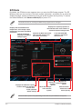
EZ Mode ..................................................................................................... 2-2
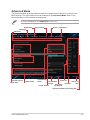
Advanced Mode ........................................................................................ 2-3
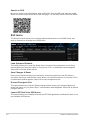
Exit menu ................................................................................................... 2-4
Appendix
Notices .......................................................................................................A-1
ASUS contact information .......................................................................A-5

iv
Safety information
Electrical safety
• To prevent electrical shock hazard, disconnect the power cable from the electrical outlet
before relocating the system.
• When adding or removing devices to or from the system, ensure that the power cables
for the devices are unplugged before the signal cables are connected. If possible,
disconnect all power cables from the existing system before you add a device.
• Before connecting or removing signal cables from the motherboard, ensure that all
power cables are unplugged.
• Seek professional assistance before using an adapter or extension cord. These devices
could interrupt the grounding circuit.
• Ensure that your power supply is set to the correct voltage in your area. If you are not
sure about the voltage of the electrical outlet you are using, contact your local power
company.
• If the power supply is broken, do not try to x it by yourself. Contact a qualied service
technician or your retailer.
Operation safety
• Before installing the motherboard and adding components, carefully read all the manuals
that came with the package.
• Before using the product, ensure all cables are correctly connected and the power
cables are not damaged. If you detect any damage, contact your dealer immediately.
• To avoid short circuits, keep paper clips, screws, and staples away from connectors,
slots, sockets and circuitry.
• Avoid dust, humidity, and temperature extremes. Do not place the product in any area
where it may be exposed to moisture.
• Place the product on a stable surface.
• If you encounter technical problems with the product, contact a qualied service
technician or your retailer.
About this guide
This user guide contains the information you need when installing and conguring the
motherboard.
How this guide is organized
This guide contains the following parts:
• Chapter 1: Product introduction
This chapter describes the features of the motherboard and the new technology it
supports. It includes descriptions of the switches, jumpers, and connectors on the
motherboard.
• Chapter 2: BIOS information
This chapter discusses changing system settings through the BIOS Setup menus.

v
Where to nd more information
Refer to the following sources for additional information and for product and software
updates.
1. ASUS websites
The ASUS website provides updated information on ASUS hardware and software
products. Refer to the ASUS contact information.
2. Optional documentation
Your product package may include optional documentation, such as warranty yers,
that may have been added by your dealer. These documents are not part of the
standard package.
Conventions used in this guide
To ensure that you perform certain tasks properly, take note of the following symbols used
throughout this manual.
DANGER/WARNING: Information to prevent injury to yourself when
completing a task.
CAUTION: Information to prevent damage to the components when
completing a task.
IMPORTANT: Instructions that you MUST follow to complete a task.
NOTE: Tips and additional information to help you complete a task.
Typography
Bold text Indicates a menu or an item to select.
Italics
Used to emphasize a word or a phrase.
<Key> Keys enclosed in the less-than and greater-than sign
means that you must press the enclosed key.
Example: <Enter> means that you must press the Enter or
Return key.
<Key1> + <Key2> + <Key3> If you must press two or more keys simultaneously, the key
names are linked with a plus sign (+).

vi
PRIME B450-PLUS specications summary
(continued on the next page)
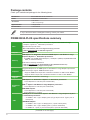
Package contents
Check your motherboard package for the following items.
Motherboard
ASUS PRIME B450-PLUS motherboard
Cables
2 x Serial ATA 6.0 Gb/s cables
Accessories
1 x I/O shield
1 x M.2 screw package
Application DVD
1 x Support DVD
Documentation
1 x User Manual
If any of the above items is damaged or missing, contact your retailer.
CPU
AM4
socket for AMD Ryzen™ 2
nd
Generation / Ryzen™ with Radeon™ Vega
Graphics / Ryzen™ 1
st
Generation processors
Supports CPU up to 8 cores*
* Due to CPU limitation, CPU cores supported vary by processor.
** Refer to www.asus.com for AMD CPU support list.
Chipset AMD B450 chipset
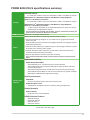
Memory
AMD Ryzen™ 2
nd
Generation Processors/AMD Ryzen™ with Radeon™ Vega
Graphics/ Ryzen™ 1
st
Generation processors:
4 x DIMM, max. 64GB, DDR4 3200(O.C.) / 3000(O.C.)/2800(O.C)/2666/2400/2133
MHz, un-buffered memory
Dual-channel memory architecture
* Refer to www.asus.com for the latest Memory QVL (Qualied Vendors List).
** ECC memory(ECC mode) support varies by CPU.
Graphics
Integrated Graphics in the AMD Ryzen™ with Radeon™ Vega Graphics processors
Multi-VGA output support: HDMI and DVI-D ports
- Supports HDMI 2.0b output with a maximum resolution of 4096 x 2160 @60Hz
- Supports DVI-D output with a maximum resolution of 1920 x 1200 @60Hz
Multi-GPU
support
Supports AMD CrossFireX™ Technology
Expansion
slots
AMD Ryzen™ 2
nd
Generation / Ryzen™ 1
st
Generation processors:
1 x PCI Express 3.0 x16 slot (max. @x16 mode)
AMD 7
th
Ryzen™ with Radeon™ Vega Graphics processors:
1 x PCI Express 3.0 x16 slot (max. @x8 mode)
AMD B450 Chipset:
1 x PCI Express 2.0 x16 slot (max. @x4 mode)
3 x PCI Express 2.0 x1 slots
USB
AMD Ryzen™ 2
nd
Generation/ Ryzen™ with Radeon™ Vega Graphics/ Ryzen™
1
st
Generation processors:
- 3 x USB 3.1 Gen 1 (up to 5Gbps) ports (2 Type A ports and 1 Type C port at
back panel)
AMD B450 Chipset:
- 2 x USB 3.1 Gen 2 (up to 10 Gbps) ports ( 2 ports at back panel)
- 2 x USB 3.1 Gen 1 (up to 5Gbps) ports ( 2 ports at mid-board)
- 6 x USB 2.0/1.1 ports ( 2 ports at back panel, 4 ports at mid-board)

vii
PRIME B450-PLUS specications summary
(continued on the next page)
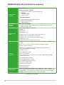
Storage
AMD B450 Chipset
- 4 x Serial ATA 6.0 Gb/s connectors with RAID 0, RAID 1 and RAID 10 support
AMD Ryzen™ 2
nd
Generation/ Ryzen™ with Radeon™ Vega Graphics/
Ryzen™ 1
st
Generation processors:
- 2 x Serial ATA 6.0 Gb/s connectors with RAID 0, RAID 1 and RAID 10 support
AMD Ryzen™ 2
nd
Generation/ Ryzen™ with Radeon™ Vega Graphics/
Ryzen™ 1
st
Generation processors:
- 1 x M.2 socket 3 with M Key, Type 2242/2260/2280/22110 (PCIe 3.0 x4 and
SATA modes) storage devices support*
* The M.2 Socket shares bandwidth with the SATA_5/6 ports, and therefore the SATA_5/6
ports cannot be used when an M.2 device is installed.
LAN Realtek
®
8111H Gigabit LAN controller
Audio
Realtek
®
ALC 887-VD2 8-Channel High Denition Audio CODEC
- LED-illuminated design: Brighten up your build with the gorgeous illuminated
audio trace path
- Audio Shielding: Ensures precision analog/digital separation and greatly reduces
multi-lateral interference
- Dedicated audio PCB layers: Separate layers for left and right channels to guard
the quality of the sensitive audio signals
- Premium Japanese audio capacitors: Provide warm, natural and immersive
sound with exceptional clarity and delity
- Supports jack-detection and front panel jack-retasking
* Use a chassis with HD audio module in the front panel to support an 8-channel audio
output.
ASUS unique
features
Dependable Stability
ASUS 5X PROTECTION III
- ASUS SafeSlot Core - Fortied PCIe Slot prevents damage
- ASUS LANGuard: Protects against LAN surges, lightning strikes and static-
electricity discharges!
- ASUS Overvoltage Protection: World-class circuit-protecting power design
- ASUS Stainless-Steel Back I/O: 3X corrosion-resistance for greater durability!
- ASUS DIGI+ VRM: 6 Phase digital power design
Superb performance
UEFI BIOS
- The most advanced options with a fast response time
ASUS Fan Xpert 4 Core
- Advanced fan and liquid controls for ultimate cooling and quietness
Gaming Scenario
Audio Features
- Audio that roars on the battleeld
ASUS Exclusive Features
- ASUS AI Charger
- ASUS File Transfer
- ASUS AI Suite 3
- ASUS PC Cleaner

viii
PRIME B450-PLUS specications summary
ASUS unique
features
Easy PC DIY
Safe motherboard mounting
- Component-free areas to minimize damage risk
Q-Design
- ASUS Q-DIMM
- ASUS Q-Slot
UEFI BIOS EZ Mode
- Featuring friendly graphics user interface
- ASUS CrashFree BIOS 3
- ASUS EZ Flash 3
ASUS Quiet
Thermal
Solution
Quiet Thermal Design:
- Stylish Fanless Design: MOS Heat-sink & Chipset Heat-sink solution
- ASUS Fan Xpert 4 core
Rear panel I/O
ports
1 x PS/2 Keyboard/Mouse combo port
1 x HDMI port
1 x DVI-D port
1 x LAN (RJ-45) port
2 x USB 3.1 Gen 2 (up to 10 Gbps) ports (Type A,teal blue)
1 x USB 3.1 Gen 1 (up to 5 Gbps) port (Type C)
2 x USB 3.1 Gen 1 (up to 5 Gbps) ports(Type A, blue)
2 x USB 2.0/1.1 ports
3 x Audio jacks support 8-channel audio output
Internal
connectors
1 x USB 3.1 Gen 1 (up to 5Gbps) connector supports additional 2 USB 3.1 Gen
1 ports
2 x USB 2.0/1.1 connectors support additional 4 USB 2.0/1.1 ports
6 x SATA 6.0 Gb/s connectors
1 x M.2 socket 3 for M Key and type 2242/2260/2280/22110 devices
support(both SATA & PCIe mode)
1 x COM connector
1 x Aura RGB Strip header
1 x CPU Fan connector
3 x 4-pin Chassis Fan connectors for both 3-pin(DC mode) and 4-pin(PWM
mode) coolers control
1 x Front panel audio connector
1 x 24-pin EATX power connector
1 x 8-pin EATX 12V power connector
1 x 2-pin Clear CMOS header
1 x System panel connector
1 x S/PDIF out connector
1 x AIO pump header
BIOS features
128 Mb Flash ROM, UEFI AMI BIOS, PnP, SM BIOS 3.1, ACPI 6.1, Multi-
language BIOS, ASUS EZ Flash 3, ASUS CrashFree BIOS 3, F3 My Favorite,
Last Modied log, F12 PrintScreen,F4 AURA ON/OFF, F9 Search and ASUS
DRAM SPD (Serial Presence Detect) memory information
(continued on the next page)

ix
Specications are subject to change without notice.
Manageability WOL by PME, PXE
Support DVD
Drivers
ASUS Utilities
ASUS Update
Anti-virus software (OEM version)
OS support Windows
®
10 (64-bit)
Form factor ATX form factor: 12” x 9.2” (30.5 cm x 23.4 cm)

ASUS PRIME B450-PLUS
1-1
Product introduction
1
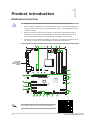
Motherboard overview
• Unplug the power cord from the wall socket before touching any component.
• Before handling components, use a grounded wrist strap or touch a safely grounded
object or a metal object, such as the power supply case, to avoid damaging them due
to static electricity.
• Before you install or remove any component, ensure that the ATX power supply is
switched off or the power cord is detached from the power supply. Failure to do so
may cause severe damage to the motherboard, peripherals, or components.
• Unplug the power cord before installing or removing the motherboard. Failure to do so
can cause you physical injury and damage to motherboard components.
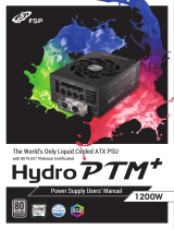
Place this
side towards
the rear of the
chassis
Scan the QR code to get the detailed pin denitions.
DDR4 DIMM_A1 (64bit, 288-pin module)
DDR4 DIMM_A2* (64bit, 288-pin module)
DDR4 DIMM_B1 (64bit, 288-pin module)
DDR4 DIMM_B2* (64bit, 288-pin module)
AIO_PUMP
CPU_FAN
CHA_FAN2
CHA_FAN3
CHA_FAN1
CLRTC
SPDIF_OUT
M.2_1(SOCKET3)
PANEL
AAFP
COM
SATA6G_6 SATA6G_5
EATX12V
EATXPWR
U31G1_12
AMD
®
B450
RTL
8111H
U31G2_12
HDMI
U31G1_C5
Super
I/O
PCIEX1_1
PCIEX1_2
228022110 2260 2242
PCIEX1_3
PCIEX16_1
PCIEX16_2
USB56 USB34
RGB_HEADER
LAN_U31G1_34
KBMS
_USB12
DVI
23.4cm(9.2in)
30.5cm(12in)
BATTERY
SOCKET AM4
AUDIO
SATA6G_1SATA6G_2
SATA6G_3SATA6G_4
128Mb
BIOS
ALC
887
LANGuard
DIGI
+VRM
6
1
7
7
2
811121314
1
5
2 2 43
910
15
15
16
16

1-2
Chapter 1: Product introduction
CPU and chassis fan connectors; AIO pump connector (4-pin CPU_FAN,
4-pin CHA_FAN1/2/3; 4-pin AIO_PUMP)
Connect the fan cables to the fan connectors on the motherboard, ensuring that the
black wire of each cable matches the ground pin of the connector.
Do not forget to connect the fan cables to the fan connectors. Insufcient air ow inside
the system may damage the motherboard components. These are not jumpers! Do not
place jumper caps on the fan connectors! The CPU_FAN connector supports a CPU fan
of maximum 1A (12 W) fan power.
AMD AM4 CPU socket
This motherboard comes with an AMD AM4 socket designed for AMD Ryzen™
2
nd
Generation / Ryzen™ with Radeon™ Vega Graphics / Ryzen™ 1
st
Generation
processors.
For more details, refer to Central Processing Unit (CPU).
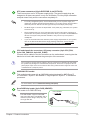
Aura RGB Strip header (4-pin RGB_HEADER)
This header is for RGB LED strip.
ATX power connectors (24-pin EATXPWR, 8-pin EATX12V)
These connectors are for ATX power supply plugs. The power supply plugs are
designed to t these connectors in only one orientation. Find the proper orientation
and push down rmly until the connectors completely t.
• For a fully congured system, we recommend that you use a power supply unit
(PSU) that complies with ATX12V Specication 2.0 (or later version) and provides a
minimum power of 350 W. This PSU type has 24-pin and 8-pin power plugs.
• DO NOT forget to connect the 8-pin EATX +12V power plug. Otherwise, the system
will not boot up.
• We recommend that you use a PSU with higher power output when conguring a
system with more power-consuming devices or when you intend to install additional
devices. The system may become unstable or may not boot up if the power is
inadequate.
•
If you are uncertain about the minimum power supply requirement for your system,
refer to the Recommended Power Supply Wattage Calculator at http://support.
asus.com/PowerSupplyCalculator/PSCalculator.aspx?SLanguage=en-us for
details.
The RGB header supports 5050 RGB
multi-color LED strips (12V/G/R/B), with a
maximum power rating of 3A (12V), and
no longer than 3m.
12VG
RB
RGB_HEADER
PIN 1
+12V G R B

ASUS PRIME B450-PLUS
1-3
Before you install or remove any component, ensure that the ATX power supply is
switched off or the power cord is detached from the power supply. Failure to do so may
cause severe damage to the motherboard, peripherals, or components.
• Actual lighting and color will vary with LED strip.
• If your LED strip does not light up, check if the RGB LED extension cable and the
RGB LED strip is connected in the correct orientation, and the 12V connector is
aligned with the 12V header on the motherboard.
• The LED strip will only light up when the system is operating.
• The LED strips are purchased separately.
DDR4 DIMM slots
Install 2 GB, 4 GB, 8 GB, and 16 GB unbuffered DDR4 DIMMs into these DIMM sockets.
For more details, refer to System memory.
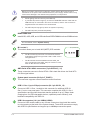
M.2 socket 3
This socket allows you to install M.2 (NGFF) SSD modules.
M.2(SOCKET3)
2280
22110
2260 2242
• The M.2 socket supports PCIe 3.0 x4 mode and SATA
mode M Key design and type 2242 / 2260 / 2280 / 22110
storage devices.
• The M.2 Socket shares bandwidth with the SATA_5/6
ports, and therefore the SATA_5/6 ports cannot be used
when an M.2 device is installed.
AMD Serial ATA 6.0Gb/s connectors (7-pin SATA6G_1~6)
These connectors connect to Serial ATA 6.0 Gb/s hard disk drives via Serial ATA
6.0 Gb/s signal cables.
System panel connector (20-5 pin F_PANEL)
This connector supports several chassis-mounted functions.
USB 3.1 Gen 1 (up to 5Gbps) connector (20-1 pin U31G1_12)
Connect a USB 3.1 Gen 1 module to this connector for additional USB 3.1
Gen 1 front or rear panel ports. This connector complies with USB 3.1 Gen 1
specications and provides faster data transfer speeds of up to 5 Gbps, faster
charging time for USB-chargeable devices, optimized power efciency, and
backward compatibility with USB 2.0.
USB 2.0 connectors (10-1 pin USB34,USB56)
Connect a USB module cable to any of these connectors, then install the module
to a slot opening at the back of the system chassis. These USB connectors comply
with USB 2.0 specications and support up to 480Mbps connection speed.

1-4
Chapter 1: Product introduction
Clear RTC RAM (2-pin CLRTC)
This header allows you to clear the CMOS RTC RAM data of
the system setup information such as date, time, and system
passwords.
To erase the RTC RAM:
1. Turn OFF the computer and unplug the power cord.
2. Use a metal object such as a screwdriver to short the
two pins.
3. Plug the power cord and turn ON the computer.
4. Hold down the <Del> key during the boot process and
enter BIOS setup to re-enter data.
CLRTC
+3V_BAT
GND
PIN 1
If the steps above do not help, remove the onboard battery and short the two pins again
to clear the CMOS RTC RAM data. After clearing the CMOS, reinstall the battery.
Serial port connector (10-1 pin COM)
This connector is for a serial (COM) port. Connect the serial port module cable to
this connector, then install the module to a slot opening at the back of the system
chassis.
Digital audio connector (4-1 pin SPDIF_OUT)
This connector is for an additional Sony/Philips Digital
Interface (S/PDIF) port. Connect the S/PDIF Out module
cable to this connector, then install the module to a slot
opening at the back of the system chassis.
SPDIF_OUT
+5V
SPDIFOUT
GND
PIN 1
Front panel audio connector (10-1 pin AAFP)
This connector is for a chassis-mounted front panel audio I/O module that supports
HD Audio standard. Connect one end of the front panel audio I/O module cable to
this connector.
We recommend that you connect a high-denition front panel audio module to this
connector to avail of the motherboard’s high-denition audio capability.
PCI Express 2.0 x1 slots
This motherboard has three PCI Express 2.0 x1 slots that support PCI Express
x1 network cards, SCSI cards, and other cards that comply with the PCI Express
specications.
PCI Express 3.0 / 2.0 x16 slots
This motherboard supports two PCI Express 3.0 / 2.0 x16 graphic cards that
comply with the PCI Express specications.

ASUS PRIME B450-PLUS
1-5
VGA Conguration
PCIe operating mode
PCIe 3.0 x16_1 PCIe 2.0 x16_2
Single VGA/PCIe card x16 N/A
Dual VGA/PCIe card x16 x4
AMD Ryzen™ 2nd Generation/ Ryzen™ 1st Generation Processors
• In single VGA card mode, use the PCIe 3.0/2.0 x16_1 slot (gray) for a PCI Express
x16 graphics card to get better performance.
• We recommend that you provide sufcient power when running CrossFireX™ mode.
• Connect chassis fans to the motherboard chassis fan connectors when using multiple
graphics cards for better thermal environment.
AMD Ryzen™ with Radeon™ Vega Graphics Processors
VGA Conguration
PCIe operating mode
PCIe 3.0 x16_1 PCIe 2.0 x16_2
Single VGA/PCIe card x8 N/A
Dual VGA/PCIe card x8 x4

1-6
Chapter 1: Product introduction
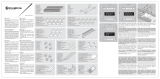
LAN port
Speed
LED
Activity Link
LED
Activity/Link LED Speed LED
Status Description Status Description
Off No link OFF 10Mbps connection
Orange Linked ORANGE 100Mbps connection
Orange
(Blinking)
Data activity GREEN 1Gbps connection
Orange
(Blinking then
steady)
Ready to wake
up from S5 mode
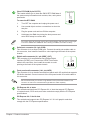
1. PS/2 Keyboard/Mouse cambo port. This port is for a PS/2 keyboard or mouse.
2. DVI-D port. This port is for any DVI-D compatible device.
DVI-D can not be converted to output from RGB Signal to CRT and is not compatible with
DVI-I.
4 5
6
8 7
2 3
9
1
11
10
Rear panel connectors
3. LAN (RJ-45) port. This port allows Gigabit connection to a Local Area Network (LAN)
through a network hub.
LAN port LED indications
4. Line In port (light blue). This port connects to the tape, CD, DVD player, or other
audio sources.
5. Line Out port (lime). This port connects to a headphone or a speaker. In the 4.1,
5.1and 7.1-channel congurations, the function of this port becomes Front Speaker
Out.
6. Microphone port (pink). This port connects to a microphone.
Refer to the audio conguration table for the function of the audio ports in 2.1, 4.1, 5.1, or
7.1-channel conguration.

ASUS PRIME B450-PLUS
1-7
7. USB 3.1 Gen 1 (up to 5Gbps) ports. These two 9-pin Universal Serial Bus (USB)
ports connect to USB 3.1 Gen 1 devices.
8. USB 3.1 Gen 2 (up to 10Gbps) ports. These 9-pin Universal Serial Bus (USB) ports
are for USB 3.1 Gen 2 devices.
• USB 3.1 Gen 1/Gen 2 devices can only be used for data storage.
• Due to the design of AMD AM4 series chipset, all USB devices connected to the USB
2.0 and USB 3.1 Gen 1/Gen 2 ports are controlled by the xHCI controller.
• We strongly recommend that you connect USB 3.1 Gen 2 devices to USB 3.1 Gen 2
ports for faster and better performance from your USB 3.1 Gen 2 devices.
9. USB 3.1 Gen 1 (up to 5Gbps) port (Type-C). This Universal Serial Bus (USB) Type C
port is for USB 3.1 Gen 1 mobile or peripheral devices.
10. HDMI port. This port is for a High-Denition Multimedia Interface (HDMI) connector,
and is HDCP compliant allowing playback of HD DVD, Blu-ray, and other protected
content.
11. USB 2.0 ports. These 4-pin Universal Serial Bus (USB) ports are for USB 2.0/1.1
devices.
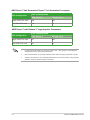
Audio 2.1, 4.1, 5.1 or 7.1-channel conguration
Port
Headset
2.1-channel
4.1-channel 5.1-channel 7.1-channel
Light Blue (Rear panel) Line In Rear Speaker Out Rear Speaker Out Rear Speaker Out
Lime (Rear panel) Line Out Front Speaker Out Front Speaker Out Front Speaker Out
Pink (Rear panel) Mic In Mic In Bass/Center Bass/Center
Lime (Front panel) - - - Side Speaker Out

1-8
Chapter 1: Product introduction
Central Processing Unit (CPU)
The motherboard comes with an AMD AM4 socket designed for AMD
Ryzen™ 2
nd
Generation / Ryzen™ with Radeon™ Vega Graphics /
Ryzen™ 1
st
Generation processors.
Unplug all power cables before installing the CPU.
The AM4 socket has a different pinout from the FM2+/FM2 socket. Ensure that you use a
CPU designed for the AM4 socket. The CPU ts in only one correct orientation. DO NOT
force the CPU into the socket to prevent bending the pins and damaging the CPU!
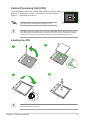
Installing the CPU
Apply the Thermal Interface Material to the CPU heatsink and CPU before you install the
heatsink and fan if necessary.
1
3
2
4

ASUS PRIME B450-PLUS
1-9
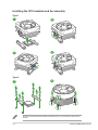
Installing the CPU heatsink and fan assembly
Type 2
Type 1
Remove the screws and the retention module only. Do not remove the plate on the
bottom.
1
1
2
2
3
4

1-10
Chapter 1: Product introduction
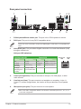
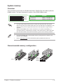
System memory
Overview
This motherboard comes with four Double Data Rate 4 (DDR4) Dual Inline Memory Module
(DIMM) sockets. The gure illustrates the location of the DDR4 DIMM sockets:
• You may install varying memory sizes in Channel A and Channel B. The system
maps the total size of the lower-sized channel for the dual-channel conguration. Any
excess memory from the higher-sized channel is then mapped for single-channel
operation.
• Always install DIMMs with the same CAS latency. For optimal compatibility, we
recommend that you install memory modules of the same version or date code (D/C)
from the same vendor. Check with the retailer to get the correct memory modules.
Recommended memory conguration
Channel Sockets
Channel A DIMM_A1 & DIMM_A2*
Channel B DIMM_B1 & DIMM_B2*
• For system stability, use a more efcient memory cooling system to support a full
memory load (4 DIMMs).
• Refer to www.asus.com for the latest Memory QVL (Qualied Vendors List)
DIMM_A2*
DIMM_B2*
DIMM_A2*
DIMM_A2*
DIMM_B2*
DIMM_A1
DIMM_B1
DIMM_A1
DIMM_A2*
DIMM_B1
DIMM_B2*

ASUS PRIME B450-PLUS
1-11
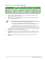
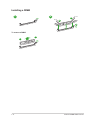
Installing a DIMM
1
2
To remove a DIMM
B
A
B
A
A
Pagina se încarcă ...
Pagina se încarcă ...
Pagina se încarcă ...
Pagina se încarcă ...
Pagina se încarcă ...
Pagina se încarcă ...
Pagina se încarcă ...
Pagina se încarcă ...
Pagina se încarcă ...
Pagina se încarcă ...
-
 1
1
-
 2
2
-
 3
3
-
 4
4
-
 5
5
-
 6
6
-
 7
7
-
 8
8
-
 9
9
-
 10
10
-
 11
11
-
 12
12
-
 13
13
-
 14
14
-
 15
15
-
 16
16
-
 17
17
-
 18
18
-
 19
19
-
 20
20
-
 21
21
-
 22
22
-
 23
23
-
 24
24
-
 25
25
-
 26
26
-
 27
27
-
 28
28
-
 29
29
-
 30
30


în alte limbi
- English: Asus PRIME B450-PLUS User manual
- italiano: Asus PRIME B450-PLUS Manuale utente
Lucrări conexe
-
Asus PRIME B450M-A/CSM Manual de utilizare
-
Asus HYPER M.2 X16 CARD V2 Manual de utilizare
-
-
-
-
-
-
-
Asus CM6870 EE7010 Manual de utilizare
-
Alte documente
-
DeLOCK 82989 Fișa cu date
-
ECS 945PL-A Manual de utilizare
-
-
-
 Hach RTC111 Basic User Manual
-
 Hach RTC Manual de utilizare
-
 Bitspower BP-FSPHP1200-EU Ghid de instalare
-
 RAIJINTEK Morpheus Core Edition Manual de utilizare
-
Genesis Irid 400 RGB Instructions of use


