
DOC023.98.90513
RTC multi-channel module
11/2018, Edition 5
User Manual
Bedienungsanleitung
Manual del usuario
Manuel de l’utilisateur
Manuale utente
Manual do utilizador
Gebruikershandleiding
Bruksanvisning
Brugervejledning
Instrukcja obsługi
Návod k použití
Ръководство за потребителя
Felhasználói kézikönyv
Navodila za uporabo
Manual de utilizare
Kullanıcı Kılavuzu
Návod na použitie
Korisnički priručnik

English..............................................................................................................................3
Deutsch.......................................................................................................................... 19
Español.......................................................................................................................... 37
Français......................................................................................................................... 56
Italiano............................................................................................................................ 74
Português...................................................................................................................... 93
Nederlands................................................................................................................. 112
Svenska....................................................................................................................... 132
Dansk............................................................................................................................149
Polski............................................................................................................................ 169
Čeština......................................................................................................................... 187
български................................................................................................................... 205
Magyar......................................................................................................................... 225
Slovenski..................................................................................................................... 243
Română....................................................................................................................... 260
Türkçe...........................................................................................................................280
Slovenský jazyk......................................................................................................... 297
Hrvatski........................................................................................................................ 316
2

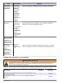
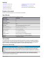
Table of contents
Specifications on page 3 RTC input and output variables values on page 9
General information on page 3 Troubleshooting on page 16
Installation on page 6 Replacement parts and accessories on page 18
Startup on page 7
Additional information
Additional information is available on the manufacturer's website.
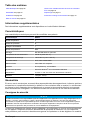
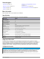
Specifications
Specifications are subject to change without notice.
Specification Details
Pollution degree 3
Protection class III
Installation category I
Degree of protection IP20
Mounting DIN rail EN 50022 or panel mount
Operating temperature 0 to 50 °C (32 to 122 °F)
Storage temperature –25 to +85 °C (–13 to +185 °F)
Relative humidity 95%, non-condensing
Flash memory CF compact flash card
Interface RJ 45 (Ethernet), 10/100 Mbit/s
Operating system Microsoft Windows
®
CE or Embedded Standard
Power supply 24 V DC or 100–240 V AC with external power supply
Warranty 1 year (EU: 2 years)
General information
In no event will the manufacturer be liable for direct, indirect, special, incidental or consequential
damages resulting from any defect or omission in this manual. The manufacturer reserves the right to
make changes in this manual and the products it describes at any time, without notice or obligation.
Revised editions are found on the manufacturer’s website.
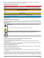
Safety information
N O T I C E
The manufacturer is not responsible for any damages due to misapplication or misuse of this product including,
without limitation, direct, incidental and consequential damages, and disclaims such damages to the full extent
permitted under applicable law. The user is solely responsible to identify critical application risks and install
appropriate mechanisms to protect processes during a possible equipment malfunction.
Please read this entire manual before unpacking, setting up or operating this equipment. Pay
attention to all danger and caution statements. Failure to do so could result in serious injury to the
operator or damage to the equipment.
English
3

Make sure that the protection provided by this equipment is not impaired. Do not use or install this
equipment in any manner other than that specified in this manual.
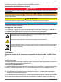
Use of hazard information
D A N G E R
Indicates a potentially or imminently hazardous situation which, if not avoided, will result in death or serious injury.
W A R N I N G
Indicates a potentially or imminently hazardous situation which, if not avoided, could result in death or serious
injury.
C A U T I O N
Indicates a potentially hazardous situation that may result in minor or moderate injury.
N O T I C E
Indicates a situation which, if not avoided, may cause damage to the instrument. Information that requires special
emphasis.
Precautionary labels
Read all labels and tags attached to the instrument. Personal injury or damage to the instrument
could occur if not observed. A symbol on the instrument is referenced in the manual with a
precautionary statement.
This symbol, if noted on the instrument, references the instruction manual for operation and/or safety
information.
This symbol indicates that a risk of electrical shock and/or electrocution exists.
Electrical equipment marked with this symbol may not be disposed of in European domestic or public
disposal systems. Return old or end-of-life equipment to the manufacturer for disposal at no charge to
the user.
Certification
Canadian Radio Interference-Causing Equipment Regulation, IECS-003, Class A:
Supporting test records reside with the manufacturer.
This Class A digital apparatus meets all requirements of the Canadian Interference-Causing
Equipment Regulations.
Cet appareil numérique de classe A répond à toutes les exigences de la réglementation canadienne
sur les équipements provoquant des interférences.
FCC Part 15, Class "A" Limits
Supporting test records reside with the manufacturer. The device complies with Part 15 of the FCC
Rules. Operation is subject to the following conditions:
1. The equipment may not cause harmful interference.
2. The equipment must accept any interference received, including interference that may cause
undesired operation.
Changes or modifications to this equipment not expressly approved by the party responsible for
compliance could void the user's authority to operate the equipment. This equipment has been tested
and found to comply with the limits for a Class A digital device, pursuant to Part 15 of the FCC rules.
These limits are designed to provide reasonable protection against harmful interference when the
4
English

equipment is operated in a commercial environment. This equipment generates, uses and can
radiate radio frequency energy and, if not installed and used in accordance with the instruction
manual, may cause harmful interference to radio communications. Operation of this equipment in a
residential area is likely to cause harmful interference, in which case the user will be required to
correct the interference at their expense. The following techniques can be used to reduce
interference problems:
1. Disconnect the equipment from its power source to verify that it is or is not the source of the
interference.
2. If the equipment is connected to the same outlet as the device experiencing interference, connect
the equipment to a different outlet.
3. Move the equipment away from the device receiving the interference.
4. Reposition the receiving antenna for the device receiving the interference.
5. Try combinations of the above.
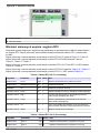
Product overview
N O T I C E
The use of a Real-Time Controller (RTC) module does not replace system maintenance. Make sure that all
instruments connected to the RTC controller are always in good condition. Regular maintenance is necessary to
make sure that the instruments supply correct, reliable measurement values. Refer to the user documentation of
each instrument.
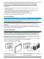
RTC modules are general application control units that make some processes better in treatment
plants. RTC modules are available as 1-channel, 2-channel or multi-channel systems.
Multi-channel RTC modules are usually operated on industrial PCs (IPC) and all input/output signals
are transferred through the sc1000 controller. Refer to the sc1000 documentation. Refer to the
documentation supplied with the hardware.
Product components
N O T I C E
The combination of pre-assembled components supplied by the manufacturer does not show an independently-
functioning unit. In accordance with EU guidelines, this combination of pre-assembled components is not supplied
with a CE mark, and there is no EU declaration of conformity for the combination. However, the conformity of the
combination of components with the guidelines can be proved through technical measurements.
Make sure that all components have been received. If any items are missing or damaged, contact the
manufacturer or a sales representative immediately.
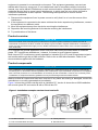
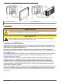
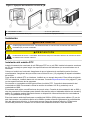
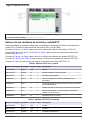
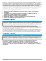
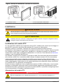
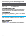
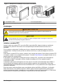
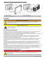
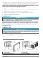
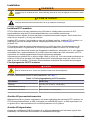
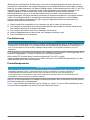
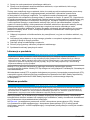
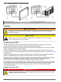
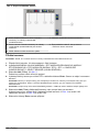
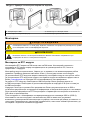
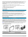
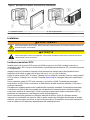
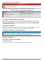
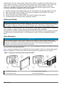
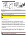
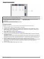
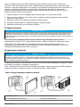
Figure 1 shows the sc1000 controller with an industrial PC. Version A shows the sc1000 installation
with a touch panel PC and version B with a DIN rail box PC.
Figure 1 Installation examples version A and version B
1 sc1000 controller 3 Touch panel PC
2 RTC communication card (2x) 4 DIN rail box PC
English 5

Installation
W A R N I N G
Potential Electrocution Hazard. Only qualified personnel should conduct the tasks described in this
section of the manual.
C A U T I O N
Possible danger to sensor or logger. Always disconnect power to the instrument when making any
electrical connections.
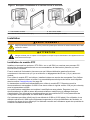
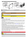
Install the RTC module
Only install RTC DIN rail versions on a DIN rail. Only install an IPC panel mount versions according
to the IPC manufacturer specifications that are supplied with the hardware.
Attach the module horizontally. Make sure that the passive aeration element operates correctly.
Make sure that there is a minimum of 30 mm (1.2 in.) of space around the module.
To use the RTC module indoors, install the module in a control cabinet. To use the RTC module
outdoors, install the module in an enclosure. Refer to Specifications on page 3 for the enclosure
specifications.
An sc1000 controller is necessary to operate the RTC module. Refer to the sc1000 controller
documentation. It is necessary to use software version V2.30 (or higher) for the sc1000 controller.
Hardware is subject to change without notice. Refer to the sc1000 documentation and other
hardware documentation for input/output electrical wiring. Additional information of RTC controllers
and setting parameters is available on the manufacturer's website.
This instrument is rated for an altitude of 2000 m (6562 ft) maximum. Use of this instrument at an
altitude higher than 2000 m can slightly increase the potential for the electrical insulation to break
down, which can result in an electric shock hazard. The manufacturer recommends that users with
concerns contact technical support.
Supply power to the RTC module
D A N G E R
Electrocution hazard. Do not connect AC power directly to a DC powered instrument.
An external deactivation switch is necessary for all installations. Refer to Table 1.
Table 1 Supply voltage of the RTC module
Specification Description
Voltage 24 V DC (-15%/+20%), 120 W (maximum)
Recommended fuse C2
With 110–240 V option 240 V, 50–60 Hz, 120 VA (maximum)
Connect to the process instruments
The measurement signals of the sc sensors, analyzer and other input signals are supplied to the
RTC module through the RTC communication card in the sc1000. For information about the power
supply of the sc1000 controller and the sc sensors, refer to the applicable documentation for the
sc1000 controller and sc sensors.
6
English

Connect to the controller
Attach the supplied SUB-D connector to a two-wire, shielded data cable (signal or bus cable). Refer
to the applicable documentation for the data cable connection.
Connect to external devices (optional)
N O T I C E
Network and access point security is the responsibility of the customer that uses the wireless instrument. The
manufacturer will not be liable for any damages, inclusive however not limited to indirect, special, consequential
or incidental damages, that have been caused by a gap in, or breach of network security.
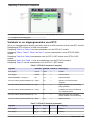
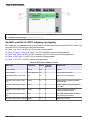
Startup
User interface and navigation
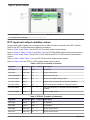
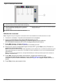
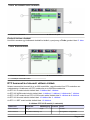
Keypad description
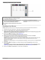
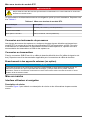
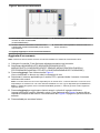
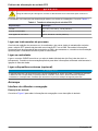
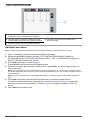
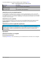
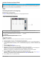
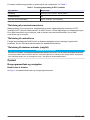
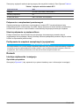
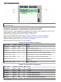
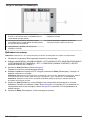
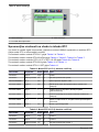
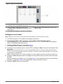
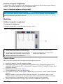
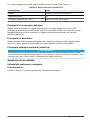
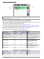
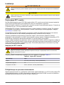
Refer to Figure 2 for the keypad description and navigation information.
Figure 2 Keypad description
1 Enter: Saves the setting and exits the current
screen to the CONFIGURE menu
4 Delete: Removes a sensor from the selection
2 Cancel: Exits the current screen to the
CONFIGURE menu without saving the setting
5 UP and DOWN arrows: Moves the sensors up or
down the list
3 Add: Adds a new sensor to the selection
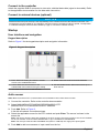
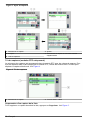
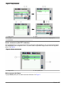
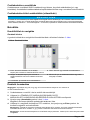
Add a sensor
Note: Make sure that an RTC communication card is installed in the sc1000 sensor module.
1. Connect the controller. Refer to the controller documentation.
2. Select MAIN MENU>RTC MODULES/PROGNOSYS>RTC
MODULES>RTC>CONFIGURE>SELECT SENSOR.
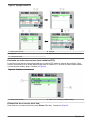
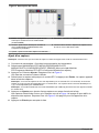
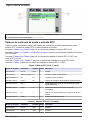
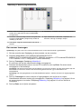
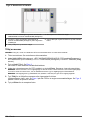
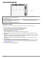
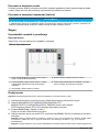
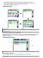
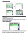
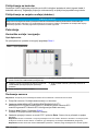
3. Push Add. Refer to Figure 3.
A list with all network connections shows.
4. Select the applicable sensor for the RTC module and push Enter. The sensor is shown in the
sensor list.
Note: The sensor names in black are available for an RTC module. The sensor names in red are not available
for an RTC module. A sensor name identified with a "(p)" is available for PROGNOSYS.
Note: The mA input cards and the PROFIBUS card (item no. YAB103) can supply RTC input signals.
5. Push Add to add more sensors or input cards from the list.
English
7

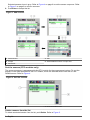
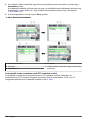
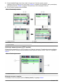
Selected sensors show in gray. Refer to Figure 4 on page 8 to set the sensor sequence. Refer
to Figure 5 on page 9 to remove a sensor.
6. Push Enter to accept the list.
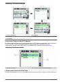
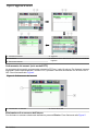
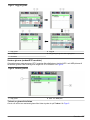
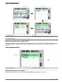
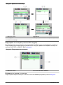
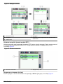
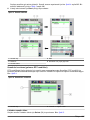
Figure 3 Add sensors
1 Select sensor 4 Add
2 Accept 5 Select additional sensor or input card
3 Sensor list
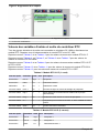
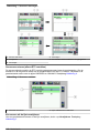
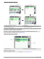
Sort the sensors (RTC modules only)
The sensor sequence is programmed in the RTC module for the measurement values. To sort the
sensors in the order specified for the RTC module, move the selected sensor with the UP and
DOWN arrows. Refer to Figure 4.
Figure 4 Sort the sensors
1 Select sensor 2 UP and DOWN arrows
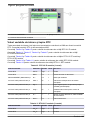
Delete a sensor from the list
To delete a selected sensor from the list, push Delete. Refer to Figure 5.
8
English

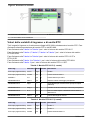
Figure 5 Delete a sensor
1 Select sensor 3 Delete the sensor
2 Go back without changes
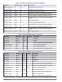
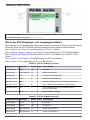
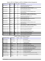
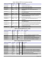
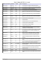
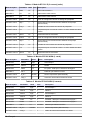
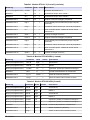
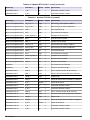
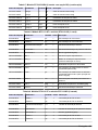
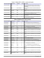
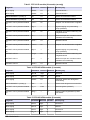
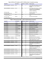
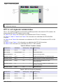
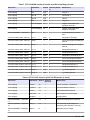
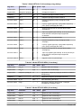
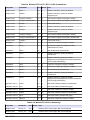
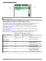
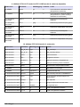
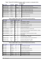
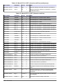
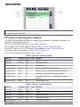
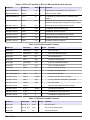
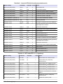
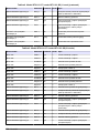
RTC input and output variables values
All input and output signals are connected to the sc1000 controller or directly to the RTC module.
Refer to the RTC module and the sc1000 documentation.
Refer to Table 2 and Table 3 for the RTC101 P-module measurement values.
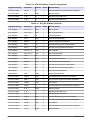
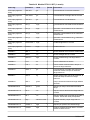
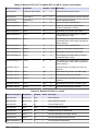
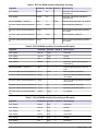
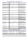
Refer to Table 4, Table 5, Table 6 and Table 7 for the RTC105 N/DN-module measurement values.
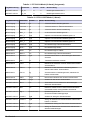
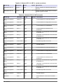
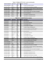
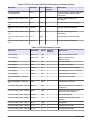
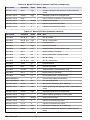
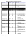
Refer to Table 8 and Table 9 for the RTC113 ST-module and RTC112 SD-module measurement
values.
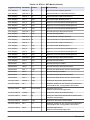
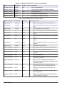
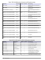
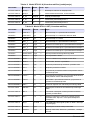
Refer to Table 10 and Table 11 for the RTC103 N-module measurement values.
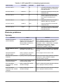
Refer to Table 12 for the RTC111 SRT-module measurement values.
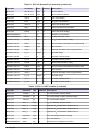
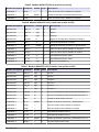
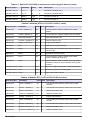
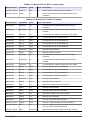
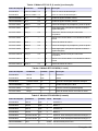
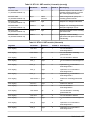
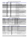
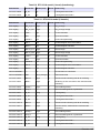
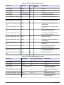
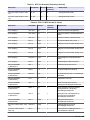
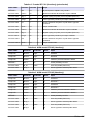
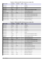
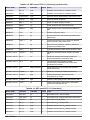
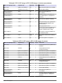
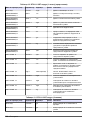
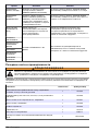
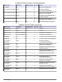
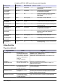
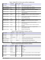
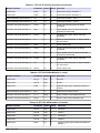
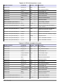
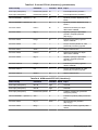
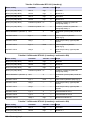
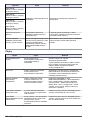
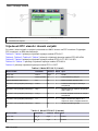
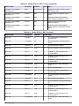
Table 2 RTC101 P-module (1-channel)
Tag name Parameter Unit Channel Description
RTC input PO
4
-P mg/L 1 Phosphate
RTC input Flow rate L/s 1 Supply volume flow
MEASUREMENT 1 Q 1 L/s 1 Wastewater flow rate
ACTUAT VAR 2 Pdos 1 L/h 1 Set point precipitant dosing volume
ACTUAT VAR 3 Digi 1 — 1 Digital output for pulsed pump operation (ON/OFF)
ACTUAT VAR 4 Preg 1 L/h 1 Internal calculation variable for precipitant volume
ACTUAT VAR 5 ß' 1 — 1 Only with open loop: ß' otherwise internal calculation
variable.
ACTUAT VAR 6 Qras 1 L/s 1 Return sludge volume
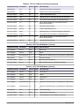
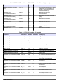
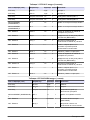
Table 3 RTC101 P-module (2-channels)
Tag name Parameter Unit Channel Description
RTC input PO
4
-P mg/L 1 Phosphate 1
RTC input PO
4
-P mg/L 2 Phosphate 2
RTC input Flow rate L/s 1 Supply volume flow 1
RTC input Flow rate L/s 2 Supply volume flow 2
English 9

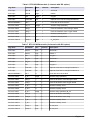
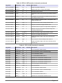
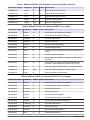
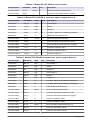
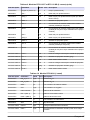
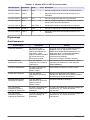
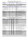
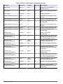
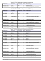
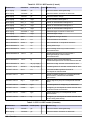
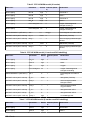
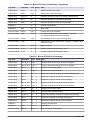
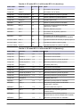
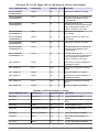
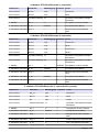
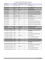
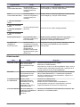
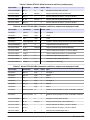
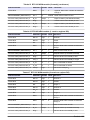
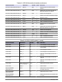
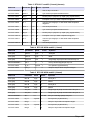
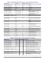
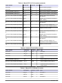
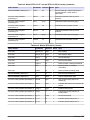
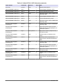
Table 3 RTC101 P-module (2-channels) (continued)
Tag name Parameter Unit Channel Description
MEASUREMENT 1 Q 1 L/s 1 Wastewater flow rate channel 1
MEASUREMENT 2 Q 2 L/s 2 Wastewater flow rate channel 2
ACTUAT VAR 3 Pdos 1 L/h 1 Set point precipitant dosing volume
ACTUAT VAR 4 Digi 1 — 1 Digital output for pulsed pump operation (ON/OFF)
ACTUAT VAR 5 Preg 1 L/h 1 Internal calculation variable for precipitant volume
ACTUAT VAR 6 ß' 1 — 1 Only with open loop: ß' otherwise internal calculation
variable.
ACTUAT VAR 7 Qras 1 L/s 1 Return sludge volume
ACTUAT VAR 8 Pdos 2 L/h 2 Set point precipitant dosing volume
ACTUAT VAR 9 Digi 2 — 2 Digital output for pulsed pump operation (ON/OFF)
ACTUAT VAR 10 Preg 2 L/h 2 Internal calculation variable for precipitant volume
ACTUAT VAR 11 ß' 2 — 2 Only with open loop: ß' otherwise internal calculation
variable.
ACTUAT VAR 12 Qras 2 L/s 2 Return sludge volume
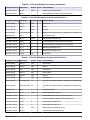
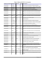
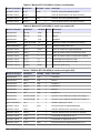
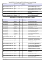
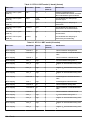
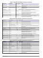
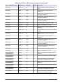
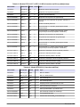
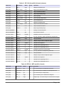
Table 4 RTC105 N/DN-module (1-channel)
Tag name Parameter Unit Channel Description
RTC input NH
4
-N mg/L 1 Ammonia
RTC input NO
3
-N mg/L 1 Nitrate
RTC input Flow rate L/s 1 Optional: Flow rate to biological treatment
MEASUREMENT 1 Qin 1 % 1 Flow rate as fed to the RTC
ACTUAT VAR 2 B_S 1 Stage 1 Blower stage (ON/OFF)
ACTUAT VAR 3 Nreg 1 — 1 Internal calculation value Nitrogen based
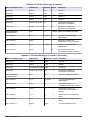
Table 5 RTC105 N/DN-module (2-channels)
Tag name Parameter Unit Channel Description
RTC input NH
4
-N mg/L 1 Ammonia 1
RTC input NO
3
-N mg/L 1 Nitrate 1
RTC input NH
4
-N mg/L 2 Ammonia 2
RTC input NO
3
-N mg/L 2 Nitrate 2
RTC input Flow rate L/s 1 Optional: Flow rate to biological treatment 1
RTC input Flow rate L/s 2 Optional: Flow rate to biological treatment 2
MEASUREMENT 1 Qin 1 % both Flow rate as fed to the RTC
ACTUAT VAR 2 B_S 1 Stage 1 Blower stage (ON/OFF)
ACTUAT VAR 3 Nreg 1 — 1 Internal calculation value Nitrogen based
ACTUAT VAR 4 B_S 2 Stage 2 Blower stage (ON/OFF)
ACTUAT VAR 5 Nreg 2 — 2 Internal calculation value Nitrogen based
10 English

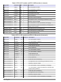
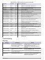
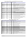
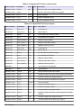
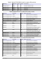
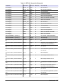
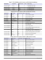
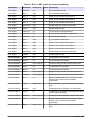
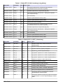
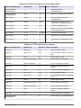
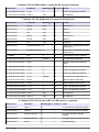
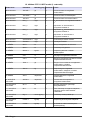
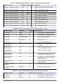
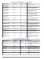
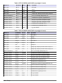
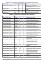
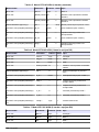
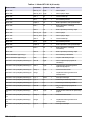
Table 6 RTC105 N/DN-module (1-channel with DO option)
Tag name Parameter Unit Channel Description
RTC input NH
4
-N mg/L 1 Ammonia
RTC input NO
3
-N mg/L 1 Nitrate
RTC input DO mg/L 1 Oxygen
RTC input Flow rate L/s 1 Optional: Flow rate to biological treatment
MEASUREMENT 1 Qin 1 % 1 Flow rate as fed to the RTC
ACTUAT VAR 2 B_S 1 Stage 1 Aeration stage (ON/OFF)
ACTUAT VAR 3 Nreg 1 — 1 Internal calculation value Nitrogen based
ACTUAT VAR 4 Oreg 1 — 1 Internal calculation value oxygen based
ACTUAT VAR 5 A_S 1 % 1 Aeration intensity VFD 1
ACTUAT VAR 6 A_S 2 % 1 Aeration intensity VFD 2
ACTUAT VAR 12 Osetp 1 mg/L 1 O
2
set point
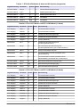
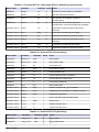
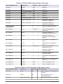
Table 7 RTC105 N/DN-module (2-channels with DO option)
Tag name Parameter Unit Channel Description
RTC input NH
4
-N mg/L 1 Ammonia 1
RTC input NO
3
-N mg/L 1 Nitrate 1
RTC input DO mg/L 1 Oxygen 1
RTC input NH
4
-N mg/L 2 Ammonia 2
RTC input NO
3
-N mg/L 2 Nitrate 2
RTC input DO mg/L 2 Oxygen 2
RTC input Flow rate L/s 1 Optional: Flow rate to biological treatment 1
RTC input Flow rate L/s 2 Optional: Flow rate to biological treatment 2
MEASUREMENT 1 Qin 1 % 1 Flow rate as fed to the RTC
ACTUAT VAR 2 B_S 1 Stage 1 Aeration stage (ON/OFF)
ACTUAT VAR 3 Nreg 1 — 1 Internal calculation value Nitrogen based
ACTUAT VAR 4 Oreg 1 — 1 Internal calculation value oxygen based
ACTUAT VAR 5 A_S 1 % 1 Aeration intensity VFD 1
ACTUAT VAR 6 A_S 2 % 1 Aeration intensity VFD 2
ACTUAT VAR 7 B_S 2 Stage 2 Aeration stage (ON/OFF) B_S 2
ACTUAT VAR 8 Nreg 2 — 2 Internal calculation value Nreg
ACTUAT VAR 9 Oreg 2 — 2 Internal calculation value Oreg
ACTUAT VAR 10 A_S 1 % 2 Aeration intensity VFD 1
ACTUAT VAR 11 A_S 2 % 2 Aeration intensity VFD 2
ACTUAT VAR 12 Osetp 1 mg/L 1 O
2
set point
ACTUAT VAR 13 Osetp 2 mg/L 2 O
2
set point
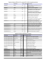
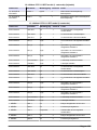
English 11

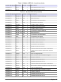
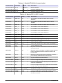
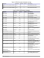
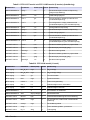
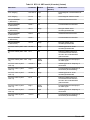
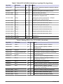
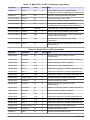
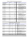
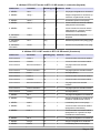
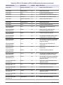
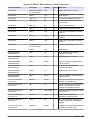
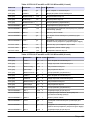
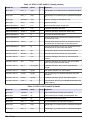
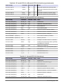
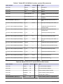
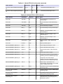
Table 8 RTC113 ST-module and RTC112 SD-module (1-channel)
Tag name Parameter Unit Channel Description
RTC input TSSin 1 g/L 1 TS concentration in inflow
RTC input TSSeff 1 g/L 1 TS concentration in effluent
RTC input Feedflow 1 L/s 1 Actual feed flow rate
RTC input Polyflow 1 L/h 1 Actual polymer flow rate
RTC input Hopper 1 — 1 Pump (ON/OFF)
MEASUREMENT 1 Qin 1 L/s 1 Actual flow rate to thickening
MEASUREMENT 2 Qavg 1 L/s 1 Averaged flow rate to thickening (as defined in menu)
MEASUREMENT 3 Qdos 1 L/h 1 Quantity of polymer added
MEASUREMENT 4 Tsin 1 g/L 1 TS concentration in inflow (modified by averaging).
MEASUREMENT 5 Tsef 1 g/L 1 TS concentration in effluent (modified by averaging and
hopper pump operation).
ACTUAT VAR 6 Pdos 1 L/h 1 Calculated set point for polymer flow
ACTUAT VAR 7 Fac 1 g/kg 1 Calculated polymer quantity (g/kg)
ACTUAT VAR 8 Feed 1 L/s 1 Calculated feed flow rate
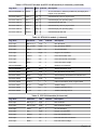
Table 9 RTC113 ST-module and RTC112 SD-module (2-channels)
Tag name Parameter Unit Channel Description
RTC input TSSin 1 g/L 1 TS concentration in inflow
RTC input TSSeff 1 g/L 1 TS concentration in effluent
RTC input Feedflow 1 L/s 1 Actual feed flow rate
RTC input Polyflow 1 L/h 1 Actual polymer flow rate
RTC input Hopper 1 — 1 Pump (ON/OFF)
RTC input TSSin 2 g/L 2 TS concentration in inflow
RTC input TSSeff 2 g/L 2 TS concentration in effluent
RTC input Feedflow 2 L/s 2 Actual feed flow rate
RTC input Polyflow 2 L/h 2 Actual polymer flow rate
RTC input Hopper 2 — 2 Pump (ON/OFF)
MEASUREMENT 1 Qin 1 L/s 2 Actual flow rate to thickening
MEASUREMENT 2 Qavg 1 L/s 1 Averaged flow rate to thickening (as defined in menu)
MEASUREMENT 3 Qdos 1 L/h 1 Quantity of polymer added
MEASUREMENT 4 Tsin 1 g/L 1 TS concentration in inflow (modified by averaging).
MEASUREMENT 5 Tsef 1 g/L 1 TS concentration in effluent (modified by averaging and
hopper pump operation).
MEASUREMENT 6 Qin 2 L/s 2 Actual flow rate to thickening
MEASUREMENT 7 Qavg 2 L/s 2 Averaged flow rate to thickening
MEASUREMENT 8 Qdos 2 L/h 2 Quantity of polymer added
MEASUREMENT 9 Tsin 2 g/L 2 TS concentration in inflow (modified by averaging).
12 English

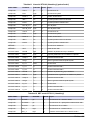
Table 9 RTC113 ST-module and RTC112 SD-module (2-channels) (continued)
Tag name Parameter Unit Channel Description
MEASUREMENT 10 Tsef 2 g/L 2 TS concentration in effluent (modified by averaging and
hopper pump operation).
ACTUAT VAR 11 Pdos 1 L/h 1 Calculated set point for polymer flow
ACTUAT VAR 12 Fac 1 g/kg 1 Calculated polymer quantity (g/kg)
ACTUAT VAR 13 Feed 1 L/s 1 Calculated feed flow rate
ACTUAT VAR 14 Pdos 2 L/h 2 Calculated set point for polymer flow
ACTUAT VAR 15 Fac 2 g/kg 2 Calculated polymer quantity (g/kg)
ACTUAT VAR 16 Feed 2 L/s 2 Calculated feed flow rate
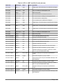
Table 10 RTC103 N-module (1-channel)
Tag name Parameter Unit Channel Description
RTC input NH
4
-N_in 1 mg/L 1 NH
4
-N influent
RTC input NH
4
-N_eff 1 mg/L 1 NH
4
-N influent effluent
RTC input TSS 1 g/L 1 TS concentration
RTC input DO 1 mg/L 1 Oxygen concentration
RTC input Inflow 1 L/s 1 Flow rate aeration lane
RTC input IRC 1 L/s 1 Flow rate internal recirculation
RTC input RAS 1 L/s 1 Flow rate return sludge
MEASUREMENT 1 — % 1 Nitrifiers concentration
MEASUREMENT 2 SRT days 1 Sludge Retention Time
ACTUAT VAR 3 NH4-N kg/h 1 NH
4
-N influent load to nitrify.
ACTUAT VAR 4 NffO 1 mg/L 1 DO necessary calculated from influent load.
ACTUAT VAR 5 Osetp 1 mg/L 1 DO set point
ACTUAT VAR 6 Oreg 1 — 1 Internal calculation value oxygen based
ACTUAT VAR 7 B_S 1 Stage 1 Aeration stage
ACTUAT VAR 8 A_S 1 % 1 Aeration intensity VFD 1
ACTUAT VAR 9 A_S 2 % 1 Aeration intensity VFD 2
Table 11 RTC103 N-module (2-channels)
Tag name Parameter Unit Channel Description
RTC input NH
4
-N_in 1 mg/L 1 NH
4
-N influent
RTC input NH
4
-N_eff 1 mg/L 1 NH
4
-N influent effluent
RTC input TSS 1 g/L 1 TS concentration
RTC input DO 1 mg/L 1 Oxygen concentration
RTC input Inflow 1 L/s 1 Flow rate aeration lane
RTC input IRC 1 L/s 1 Flow rate internal recirculation
RTC input RAS 1 L/s 1 Flow rate return sludge
English 13

Table 11 RTC103 N-module (2-channels) (continued)
Tag name Parameter Unit Channel Description
RTC input NH
4
-N_in 2 mg/L 2 NH
4
-N influent
RTC input NH
4
-N_eff 2 mg/L 2 NH
4
-N influent effluent
RTC input TSS 2 g/L 2 TS concentration
RTC input DO 2 mg/L 2 Oxygen concentration
RTC input Inflow 2 L/s 2 Flow rate aeration lane
RTC input IRC 2 L/s 2 Flow rate internal recirculation
RTC input RAS 2 L/s 2 Flow rate return sludge
MEASUREMENT 1 — % 1 Nitrifiers concentration
MEASUREMENT 2 SRT days 1 Sludge Retention Time
ACTUAT VAR 3 NH4-N kg/h 1 NH
4
-N influent load to nitrify.
ACTUAT VAR 4 NffO 1 mg/L 1 DO necessary calculation from influent load.
ACTUAT VAR 5 Osetp 1 mg/L 1 DO set point
ACTUAT VAR 6 Oreg 1 — 1 Internal calculation value oxygen based
ACTUAT VAR 7 B_S 1 Stage 1 Aeration stage
ACTUAT VAR 8 A_S 1 % 1 Aeration intensity VFD 1
ACTUAT VAR 9 A_S 2 % 1 Aeration intensity VFD 2
ACTUAT VAR 10 NH4-N kg/h 2 NH
4
-N influent load to nitrify.
ACTUAT VAR 11 NffO 2 mg/L 2 DO necessary calculated from influent load.
ACTUAT VAR 12 Osetp 2 mg/L 2 DO set point
ACTUAT VAR 13 Oreg 2 — 2 Internal calculation value oxygen based
ACTUAT VAR 14 B_S 2 Stage 2 Aeration stage
ACTUAT VAR 15 A_S 1 % 2 Aeration intensity VFD 1
ACTUAT VAR 16 A_S 2 % 2 Aeration intensity VFD 2
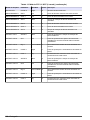
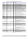
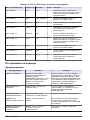
Table 12 RTC111 SRT-module (1-channel)
Tag name Parameter Unit Channel Description
RTC input TSS AE 1 g/L 1 TS concentration aeration basin
RTC input TSS SAS 1 g/L 1 TS concentration surplus activated sludge
RTC input TSS eff 1 g/L 1 TS concentration effluent
RTC input DO1_1 mg/L 1 O
2
concentration aeration zone 1
RTC input DO1_2 mg/L 1 Optional: O
2
concentration aeration zone 2
RTC input DO1_3 mg/L 1 Optional: O
2
concentration aeration zone 3
RTC input DO1_4 mg/L 1 Optional: O
2
concentration aeration zone 4
RTC input SAS flow 1 mg/L 1 Flow rate surplus activated sludge
RTC input Flow 1 mg/L 1 Flow rate influent
MEASUREMENT 1 Qeff 1 L/s 1 Effluent flow as supplied to the RTC.
14 English

Table 12 RTC111 SRT-module (1-channel) (continued)
Tag name Parameter Unit Channel Description
MEASUREMENT 2 Qsas 1 L/s 1 Surplus activated sludge flow
MEASUREMENT 3 Qsasm 1 kg/h 1 Sludge mass flow in surplus start sludge
MEASUREMENT 4 Vol 1 m
3
1 Actually aerated volume
MEASUREMENT 5 Vols 1 m
3
1 Averaged aerated volume during past sludge retention
time.
MEASUREMENT 6 TSmL 1 g/L 1 Averaged TS concentration in aeration basins during
past sludge retention time.
MEASUREMENT 7 TSs s1 kg 1 Mass of sludge in aeration basins, averaged for past
sludge retention time.
MEASUREMENT 8 SRT 1 days 1 Calculated actual aerobic sludge retention time
ACTUAT VAR 9 SRTSP 1 days 1 Set point for aerobic sludge retention time
ACTUAT VAR 10 Qs c1 L/s 1 Theoretical flow set point for surplus start sludge flow
ACTUAT VAR 11 Qs 1 L/s 1 Effective set point for surplus activated sludge flow
including all preset limits.
ACTUAT VAR 12 Digi 1 no unit 1 Surplus activated sludge pump ON/OFF signal
ACTUAT VAR 13 msaSP 1 kg/d 1 Set point for sludge mass draws off.
ACTUAT VAR 14 msasd 1 kg/d 1 Surplus activated sludge mass draw off during last
24 hours.
ACTUAT VAR 15 msash 1 kg/h 1 Actual surplus activated sludge mass draw off.
ACTUAT VAR 16 msas 1 kg 1 Surplus activated sludge mass draw off during actual
calendar day.
Table 13 RTC111 SRT-module (2-channels)
Tag name Parameter Unit Channel Description
RTC input TSS AE 1 g/L 1 TS concentration aeration basin
RTC input TSS SAS 1 g/L 1 TS concentration surplus activated sludge
RTC input TSS eff 1 g/L 1 TS concentration effluent
RTC input DO1_1 mg/L 1 O
2
concentration aeration zone 1
RTC input DO1_2 mg/L 1 Optional: O
2
concentration aeration zone 2
RTC input DO1_3 mg/L 1 Optional: O
2
concentration aeration zone 3
RTC input DO1_4 mg/L 1 Optional: O
2
concentration aeration zone 4
RTC input SAS flow 1 mg/L 1 Flow rate surplus activated sludge
RTC input Flow 1 mg/L 1 Flow rate influent
RTC input TSS AE 2 g/L 2 TS concentration aeration basin
RTC input TSS SAS 2 g/L 2 TS concentration surplus activated sludge
RTC input TSS eff 2 g/L 2 TS concentration effluent
RTC input DO2_1 mg/L 2 O
2
concentration aeration zone 1
RTC input DO2_2 mg/L 2 Optional: O
2
concentration aeration zone 2
English 15

Table 13 RTC111 SRT-module (2-channels) (continued)
Tag name Parameter Unit Channel Description
RTC input DO2_3 mg/L 2 Optional: O
2
concentration aeration zone 3
RTC input DO2_4 mg/L 2 Optional: O
2
concentration aeration zone 4
RTC input SAS flow 2 mg/L 2 Flow rate surplus activated sludge
RTC input Flow 2 mg/L 2 Flow rate influent
MEASUREMENT 1 Qeff 1 L/s 1 Effluent flow as supplied to the RTC.
MEASUREMENT 2 Qsas 1 L/s 1 Surplus activated sludge flow
MEASUREMENT 3 SRT 1 days 1 Calculated actual aerobic sludge retention time
MEASUREMENT 4 Qeff 2 L/s 2 Effluent flow as supplied to the RTC.
MEASUREMENT 5 Qsas 2 L/s 2 Surplus activated sludge flow
MEASUREMENT 6 SRT 2 days 2 Calculated actual aerobic sludge retention time
ACTUAT VAR 7 SRTSP 1 days 1 Set point for aerobic sludge retention time
ACTUAT VAR 8 Qs 1 L/s 1 Effective set point for surplus activated sludge flow
including all preset limits.
ACTUAT VAR 9 Digi 1 no unit 1 Surplus activated sludge pump ON/OFF signal
ACTUAT VAR 10 msaSP 1 kg/d 1 Set point for sludge mass draws off.
ACTUAT VAR 11 msas 1 kg 1 Surplus activated sludge mass draw off during actual
calendar day.
ACTUAT VAR 12 SRTSP 2 days 2 Set point for aerobic sludge retention time
ACTUAT VAR 13 Qs 2 L/s 2 Effective set point for surplus activated sludge flow
including all preset limits.
ACTUAT VAR 14 Digi 2 no unit 2 Surplus activated sludge pump ON/OFF signal
ACTUAT VAR 15 msaSP 2 kg/d 2 Set point for sludge mass draws off.
ACTUAT VAR 16 msas 2 kg 2 Surplus activated sludge mass draw off during actual
calendar day.
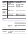
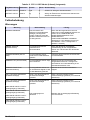
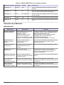
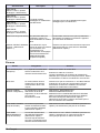
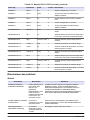
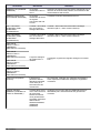
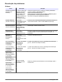
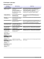
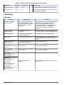
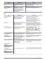
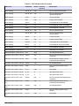
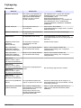
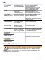
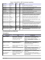
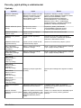
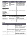
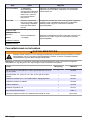
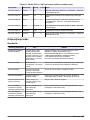
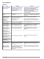
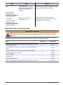
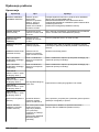
Troubleshooting
Warnings
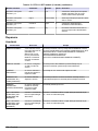
Warning Description Solution
MODBUS ADDRESS The RTC menu SET DEFAULTS
was selected. This deleted the
Modbus address of the RTC module
in the sc1000 controller.
Access the following menu and set the correct
MODBUS address. Go to: MAIN MENU>RTC
MODULES/PROGNOSYS> RTC
MODULES>RTC> CONFIGURE>MODBUS>
ADDRESS.
PROBE SERVICE A configured sensor is in service
mode.
Go to the TEST/MAINT menu of selected sensor
and end the SERVICE mode.
SENSOR MISSING A selected sensor was disconnected
from the sc1000 network.
Connect the sensor to sc1000 network again.
SENSOR FAIL A selected sensor shows an error. Look at the error mode of selected sensors.
Refer to the sensor documentation for
troubleshooting information.
16 English

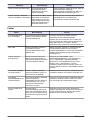
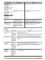
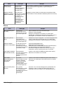
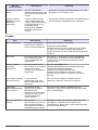
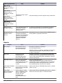
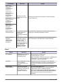
Warning Description Solution
SENSOR
EXCEPTION
A selected sensor supplied an
unknown signal to the
sc1000 network.
Contact technical support.
CH1: FALLBACK
STRATEGY
Channel 1 of the RTC module
started the substitutional strategy.
Channel 1 of the RTC module started the
substitutional strategy (e.g., missing
measurement values).
CH2: FALLBACK
STRATEGY
Channel 2 of the RTC module
started the substitutional strategy.
Channel 2 of the RTC module started the
substitutional strategy (e.g., missing
measurement values).
ANALOGUE
INPUT1 FAULTY
RTC analogue input signal is
defective.
Fix the analogue signal supply to RTC module.
ANALOGUE
INPUT2 FAULTY
ANALOGUE
INPUT3 FAULTY
ANALOGUE
INPUT4 FAULTY
LIMIT ACTIVE A user-defined parameter sets a
limit for the RTC operation.
If necessary, make sure that the limiting
parameters are correctly set. Make necessary
adjustments.
CHECK "SELECT
SENSOR"
RTC module receives less
measurement values than
necessary. This warning likely
occurs with the SENSOR MISSING
warning.
Make sure that all necessary instruments are
selected in the SELECT SENSOR menu.
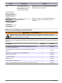
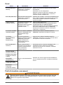
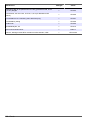
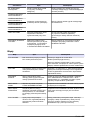
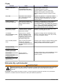
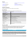
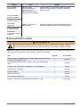
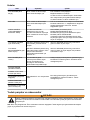
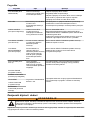
Errors
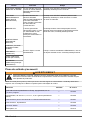
Error Description Solution
RTC MISSING There is no communication
between RTC module and
RTC communication card.
Supply RTC module with voltage.
Examine the connection cable.
Set the power of the sc1000 and the RTC module to
off. Wait until the system is completely voltage free. Set
the power of the sc1000 controller and the RTC module
to on.
RTC CRC The communication between
RTC module and RTC
communication card was
cancelled.
Make sure that the +/- connections of the connector
cable between RTC and RTC communication card in
the sc1000 are installed correctly. Make the necessary
changes.
CHECK CONFIG The sensor selection of the
RTC module was removed by
removal or selection of a new
sc1000 controller.
Go to: MAIN MENU>RTC
MODULES/PROGNOSYS>RTC MODULES>RTC>
CONFIGURE>SELECT SENSOR, select the correct
sensor for the RTC again and confirm.
TOO MANY PROBES Too many sensors selected in
the SELECT SENSOR menu.
Go to the SELECT SENSOR menu. Select no more
than 15 probes.
TOO MANY
MEASUREMENTS
The probes selected in the
SELECT SENSOR have too
many measurements to be
operates by the RTC
communication card.
Go to the SELECT SENSOR menu. Select the number
of probes that have no more than 15 measurement
values.
English 17

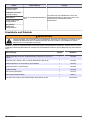
Error Description Solution
RTC FAILURE A general reading/writing error
of on CF card, which was most
likely caused by a brief
interruption to the power
supply.
Acknowledge the error. If the message frequently
shows, remove the cause of power disruptions. If
necessary, contact technical support.
SYNTAX ERROR
Error in PROGNOSYS *.bin-
file.
Use an updated version of PROGNOSYS that does not
show this error. Contact technical support.
FORMULA TO LONG
ARGUMENT
LOGIC FUNCTION
BOUNDARY
FUNCTION
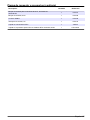
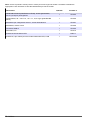
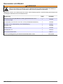
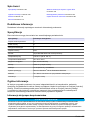
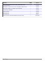
Replacement parts and accessories
W A R N I N G
Personal injury hazard. Use of non-approved parts may cause personal injury, damage to the
instrument or equipment malfunction. The replacement parts in this section are approved by the
manufacturer.
Note: Product and Article numbers may vary for some selling regions. Contact the appropriate distributor or refer to
the company website for contact information.
Description Quantity Item no.
DIN rail NS 35/15 (DIN EN 60715 TH35), galvanized steel, 35 cm
(13.78 in.) length
1 LZH165
Transformer, 90–240 V AC, 24 V DC, 0.75 A (for DIN rail NS 35/15) 1 LZH166
Terminal block for 24 V connection, without power supply 1 LZH167
Terminal block, grounding 1 LZH168
SUB-D connector 1 LZH169
Circuit breaker, C2 1 LZH170
RTC communication card 1 YAB117
CF card, basic type for all RTC multi-channel modules, 8 GB 1 LZY748-A0
18 English

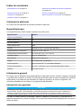
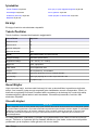
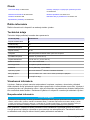
Inhaltsverzeichnis
Technische Daten auf Seite 19 Werte der RTC-Eingangs- und -ausgangsvariablen
auf Seite 26
Allgemeine Informationen auf Seite 19 Fehlerbehebung auf Seite 34
Installation auf Seite 22 Ersatzteile und Zubehör auf Seite 36
Inbetriebnahme auf Seite 23
Zusätzliche Informationen
Zusätzliche Informationen finden Sie auf der Website des Herstellers.
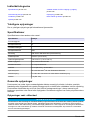
Technische Daten
Änderungen vorbehalten.
Technische Daten Details
Verschmutzungsgrad 3
Schutzklasse III
Einbaukategorie I
Schutzgrad IP20
Befestigung DIN-Schiene EN 50022 oder Tafelmontage
Betriebstemperatur 0 bis 50 °C
Lagerungstemperatur –25 bis +85 °C (–13 bis +185 °F)
Relative Luftfeuchtigkeit 95 %, nicht kondensierend
Flash-Speicher CF Compact-Flash-Karte
Schnittstelle RJ 45 (Ethernet), 10/100 Mbit/s
Betriebssystem Microsoft Windows
®
CE oder Embedded Standard
Netzteil 24 V DC oder 100-240 V AC über externe Stromversorgung
Garantie 1 Jahr (EU: 2 Jahre)
Allgemeine Informationen
Der Hersteller ist nicht verantwortlich für direkte, indirekte, versehentliche oder Folgeschäden, die
aus Fehlern oder Unterlassungen in diesem Handbuch entstanden. Der Hersteller behält sich
jederzeit und ohne vorherige Ankündigung oder Verpflichtung das Recht auf Verbesserungen an
diesem Handbuch und den hierin beschriebenen Produkten vor. Überarbeitete Ausgaben der
Bedienungsanleitung sind auf der Hersteller-Webseite erhältlich.
Sicherheitshinweise
H I N W E I S
Der Hersteller ist nicht für Schäden verantwortlich, die durch Fehlanwendung oder Missbrauch dieses Produkts
entstehen, einschließlich, aber ohne Beschränkung auf direkte, zufällige oder Folgeschäden, und lehnt jegliche
Haftung im gesetzlich zulässigen Umfang ab. Der Benutzer ist selbst dafür verantwortlich, schwerwiegende
Anwendungsrisiken zu erkennen und erforderliche Maßnahmen durchzuführen, um die Prozesse im Fall von
möglichen Gerätefehlern zu schützen.
Deutsch 19

Bitte lesen Sie dieses Handbuch komplett durch, bevor Sie dieses Gerät auspacken, aufstellen oder
bedienen. Beachten Sie alle Gefahren- und Warnhinweise. Nichtbeachtung kann zu schweren
Verletzungen des Bedieners oder Schäden am Gerät führen.
Stellen Sie sicher, dass die durch dieses Messgerät bereitgestellte Sicherheit nicht beeinträchtigt
wird. Verwenden bzw. installieren Sie das Messsystem nur wie in diesem Handbuch beschrieben.
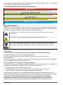
Bedeutung von Gefahrenhinweisen
G E F A H R
Kennzeichnet eine mögliche oder drohende Gefahrensituation, die, wenn sie nicht vermieden wird, zum Tod oder
zu schweren Verletzungen führt.
W A R N U N G
Kennzeichnet eine mögliche oder drohende Gefahrensituation, die, wenn sie nicht vermieden wird, zum Tod oder
zu schweren Verletzungen führen kann.
V O R S I C H T
Kennzeichnet eine mögliche Gefahrensituation, die zu geringeren oder moderaten Verletzungen führen kann.
H I N W E I S
Kennzeichnet eine Situation, die, wenn sie nicht vermieden wird, das Gerät beschädigen kann. Informationen, die
besonders beachtet werden müssen.
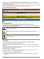
Warnhinweise
Lesen Sie alle am Gerät angebrachten Aufkleber und Hinweise. Nichtbeachtung kann Verletzungen
oder Beschädigungen des Geräts zur Folge haben. Im Handbuch wird in Form von Warnhinweisen
auf die am Gerät angebrachten Symbole verwiesen.
Dieses Symbol am Gerät weist auf Betriebs- und/oder Sicherheitsinformationen im Handbuch hin.
Dieses Symbol weist auf die Gefahr eines elektrischen Schlages hin, der tödlich sein kann.
Elektrogeräte, die mit diesem Symbol gekennzeichnet sind, dürfen nicht im normalen öffentlichen
Abfallsystem entsorgt werden. Senden Sie Altgeräte an den Hersteller zurück. Dieser entsorgt die
Geräte ohne Kosten für den Benutzer.
Zertifizierung
Kanadische Vorschriften zu Störungen verursachenden Einrichtungen, IECS-003, Klasse A:
Entsprechende Prüfprotokolle hält der Hersteller bereit.
Dieses digitale Gerät der Klasse A erfüllt alle Vorgaben der kanadischen Normen für Interferenz
verursachende Geräte.
Cet appareil numérique de classe A répond à toutes les exigences de la réglementation canadienne
sur les équipements provoquant des interférences.
FCC Teil 15, Beschränkungen der Klasse "A"
Entsprechende Prüfprotokolle hält der Hersteller bereit. Das Gerät entspricht Teil 15 der FCC-
Vorschriften. Der Betrieb unterliegt den folgenden Bedingungen:
1. Das Gerät darf keine Störungen verursachen.
2. Das Gerät muss jegliche Störung, die es erhält, einschließlich jener Störungen, die zu
unerwünschtem Betrieb führen, annehmen.
20
Deutsch
Pagina se încarcă...
Pagina se încarcă...
Pagina se încarcă...
Pagina se încarcă...
Pagina se încarcă...
Pagina se încarcă...
Pagina se încarcă...
Pagina se încarcă...
Pagina se încarcă...
Pagina se încarcă...
Pagina se încarcă...
Pagina se încarcă...
Pagina se încarcă...
Pagina se încarcă...
Pagina se încarcă...
Pagina se încarcă...
Pagina se încarcă...
Pagina se încarcă...
Pagina se încarcă...
Pagina se încarcă...
Pagina se încarcă...
Pagina se încarcă...
Pagina se încarcă...
Pagina se încarcă...
Pagina se încarcă...
Pagina se încarcă...
Pagina se încarcă...
Pagina se încarcă...
Pagina se încarcă...
Pagina se încarcă...
Pagina se încarcă...
Pagina se încarcă...
Pagina se încarcă...
Pagina se încarcă...
Pagina se încarcă...
Pagina se încarcă...
Pagina se încarcă...
Pagina se încarcă...
Pagina se încarcă...
Pagina se încarcă...
Pagina se încarcă...
Pagina se încarcă...
Pagina se încarcă...
Pagina se încarcă...
Pagina se încarcă...
Pagina se încarcă...
Pagina se încarcă...
Pagina se încarcă...
Pagina se încarcă...
Pagina se încarcă...
Pagina se încarcă...
Pagina se încarcă...
Pagina se încarcă...
Pagina se încarcă...
Pagina se încarcă...
Pagina se încarcă...
Pagina se încarcă...
Pagina se încarcă...
Pagina se încarcă...
Pagina se încarcă...
Pagina se încarcă...
Pagina se încarcă...
Pagina se încarcă...
Pagina se încarcă...
Pagina se încarcă...
Pagina se încarcă...
Pagina se încarcă...
Pagina se încarcă...
Pagina se încarcă...
Pagina se încarcă...
Pagina se încarcă...
Pagina se încarcă...
Pagina se încarcă...
Pagina se încarcă...
Pagina se încarcă...
Pagina se încarcă...
Pagina se încarcă...
Pagina se încarcă...
Pagina se încarcă...
Pagina se încarcă...
Pagina se încarcă...
Pagina se încarcă...
Pagina se încarcă...
Pagina se încarcă...
Pagina se încarcă...
Pagina se încarcă...
Pagina se încarcă...
Pagina se încarcă...
Pagina se încarcă...
Pagina se încarcă...
Pagina se încarcă...
Pagina se încarcă...
Pagina se încarcă...
Pagina se încarcă...
Pagina se încarcă...
Pagina se încarcă...
Pagina se încarcă...
Pagina se încarcă...
Pagina se încarcă...
Pagina se încarcă...
Pagina se încarcă...
Pagina se încarcă...
Pagina se încarcă...
Pagina se încarcă...
Pagina se încarcă...
Pagina se încarcă...
Pagina se încarcă...
Pagina se încarcă...
Pagina se încarcă...
Pagina se încarcă...
Pagina se încarcă...
Pagina se încarcă...
Pagina se încarcă...
Pagina se încarcă...
Pagina se încarcă...
Pagina se încarcă...
Pagina se încarcă...
Pagina se încarcă...
Pagina se încarcă...
Pagina se încarcă...
Pagina se încarcă...
Pagina se încarcă...
Pagina se încarcă...
Pagina se încarcă...
Pagina se încarcă...
Pagina se încarcă...
Pagina se încarcă...
Pagina se încarcă...
Pagina se încarcă...
Pagina se încarcă...
Pagina se încarcă...
Pagina se încarcă...
Pagina se încarcă...
Pagina se încarcă...
Pagina se încarcă...
Pagina se încarcă...
Pagina se încarcă...
Pagina se încarcă...
Pagina se încarcă...
Pagina se încarcă...
Pagina se încarcă...
Pagina se încarcă...
Pagina se încarcă...
Pagina se încarcă...
Pagina se încarcă...
Pagina se încarcă...
Pagina se încarcă...
Pagina se încarcă...
Pagina se încarcă...
Pagina se încarcă...
Pagina se încarcă...
Pagina se încarcă...
Pagina se încarcă...
Pagina se încarcă...
Pagina se încarcă...
Pagina se încarcă...
Pagina se încarcă...
Pagina se încarcă...
Pagina se încarcă...
Pagina se încarcă...
Pagina se încarcă...
Pagina se încarcă...
Pagina se încarcă...
Pagina se încarcă...
Pagina se încarcă...
Pagina se încarcă...
Pagina se încarcă...
Pagina se încarcă...
Pagina se încarcă...
Pagina se încarcă...
Pagina se încarcă...
Pagina se încarcă...
Pagina se încarcă...
Pagina se încarcă...
Pagina se încarcă...
Pagina se încarcă...
Pagina se încarcă...
Pagina se încarcă...
Pagina se încarcă...
Pagina se încarcă...
Pagina se încarcă...
Pagina se încarcă...
Pagina se încarcă...
Pagina se încarcă...
Pagina se încarcă...
Pagina se încarcă...
Pagina se încarcă...
Pagina se încarcă...
Pagina se încarcă...
Pagina se încarcă...
Pagina se încarcă...
Pagina se încarcă...
Pagina se încarcă...
Pagina se încarcă...
Pagina se încarcă...
Pagina se încarcă...
Pagina se încarcă...
Pagina se încarcă...
Pagina se încarcă...
Pagina se încarcă...
Pagina se încarcă...
Pagina se încarcă...
Pagina se încarcă...
Pagina se încarcă...
Pagina se încarcă...
Pagina se încarcă...
Pagina se încarcă...
Pagina se încarcă...
Pagina se încarcă...
Pagina se încarcă...
Pagina se încarcă...
Pagina se încarcă...
Pagina se încarcă...
Pagina se încarcă...
Pagina se încarcă...
Pagina se încarcă...
Pagina se încarcă...
Pagina se încarcă...
Pagina se încarcă...
Pagina se încarcă...
Pagina se încarcă...
Pagina se încarcă...
Pagina se încarcă...
Pagina se încarcă...
Pagina se încarcă...
Pagina se încarcă...
Pagina se încarcă...
Pagina se încarcă...
Pagina se încarcă...
Pagina se încarcă...
Pagina se încarcă...
Pagina se încarcă...
Pagina se încarcă...
Pagina se încarcă...
Pagina se încarcă...
Pagina se încarcă...
Pagina se încarcă...
Pagina se încarcă...
Pagina se încarcă...
Pagina se încarcă...
Pagina se încarcă...
Pagina se încarcă...
Pagina se încarcă...
Pagina se încarcă...
Pagina se încarcă...
Pagina se încarcă...
Pagina se încarcă...
Pagina se încarcă...
Pagina se încarcă...
Pagina se încarcă...
Pagina se încarcă...
Pagina se încarcă...
Pagina se încarcă...
Pagina se încarcă...
Pagina se încarcă...
Pagina se încarcă...
Pagina se încarcă...
Pagina se încarcă...
Pagina se încarcă...
Pagina se încarcă...
Pagina se încarcă...
Pagina se încarcă...
Pagina se încarcă...
Pagina se încarcă...
Pagina se încarcă...
Pagina se încarcă...
Pagina se încarcă...
Pagina se încarcă...
Pagina se încarcă...
Pagina se încarcă...
Pagina se încarcă...
Pagina se încarcă...
Pagina se încarcă...
Pagina se încarcă...
Pagina se încarcă...
Pagina se încarcă...
Pagina se încarcă...
Pagina se încarcă...
Pagina se încarcă...
Pagina se încarcă...
Pagina se încarcă...
Pagina se încarcă...
Pagina se încarcă...
Pagina se încarcă...
Pagina se încarcă...
Pagina se încarcă...
Pagina se încarcă...
Pagina se încarcă...
Pagina se încarcă...
Pagina se încarcă...
Pagina se încarcă...
Pagina se încarcă...
Pagina se încarcă...
Pagina se încarcă...
Pagina se încarcă...
Pagina se încarcă...
Pagina se încarcă...
Pagina se încarcă...
Pagina se încarcă...
Pagina se încarcă...
Pagina se încarcă...
Pagina se încarcă...
Pagina se încarcă...
Pagina se încarcă...
Pagina se încarcă...
Pagina se încarcă...
Pagina se încarcă...
Pagina se încarcă...
Pagina se încarcă...
Pagina se încarcă...
Pagina se încarcă...
Pagina se încarcă...
Pagina se încarcă...
Pagina se încarcă...
Pagina se încarcă...
Pagina se încarcă...
-
 1
1
-
 2
2
-
 3
3
-
 4
4
-
 5
5
-
 6
6
-
 7
7
-
 8
8
-
 9
9
-
 10
10
-
 11
11
-
 12
12
-
 13
13
-
 14
14
-
 15
15
-
 16
16
-
 17
17
-
 18
18
-
 19
19
-
 20
20
-
 21
21
-
 22
22
-
 23
23
-
 24
24
-
 25
25
-
 26
26
-
 27
27
-
 28
28
-
 29
29
-
 30
30
-
 31
31
-
 32
32
-
 33
33
-
 34
34
-
 35
35
-
 36
36
-
 37
37
-
 38
38
-
 39
39
-
 40
40
-
 41
41
-
 42
42
-
 43
43
-
 44
44
-
 45
45
-
 46
46
-
 47
47
-
 48
48
-
 49
49
-
 50
50
-
 51
51
-
 52
52
-
 53
53
-
 54
54
-
 55
55
-
 56
56
-
 57
57
-
 58
58
-
 59
59
-
 60
60
-
 61
61
-
 62
62
-
 63
63
-
 64
64
-
 65
65
-
 66
66
-
 67
67
-
 68
68
-
 69
69
-
 70
70
-
 71
71
-
 72
72
-
 73
73
-
 74
74
-
 75
75
-
 76
76
-
 77
77
-
 78
78
-
 79
79
-
 80
80
-
 81
81
-
 82
82
-
 83
83
-
 84
84
-
 85
85
-
 86
86
-
 87
87
-
 88
88
-
 89
89
-
 90
90
-
 91
91
-
 92
92
-
 93
93
-
 94
94
-
 95
95
-
 96
96
-
 97
97
-
 98
98
-
 99
99
-
 100
100
-
 101
101
-
 102
102
-
 103
103
-
 104
104
-
 105
105
-
 106
106
-
 107
107
-
 108
108
-
 109
109
-
 110
110
-
 111
111
-
 112
112
-
 113
113
-
 114
114
-
 115
115
-
 116
116
-
 117
117
-
 118
118
-
 119
119
-
 120
120
-
 121
121
-
 122
122
-
 123
123
-
 124
124
-
 125
125
-
 126
126
-
 127
127
-
 128
128
-
 129
129
-
 130
130
-
 131
131
-
 132
132
-
 133
133
-
 134
134
-
 135
135
-
 136
136
-
 137
137
-
 138
138
-
 139
139
-
 140
140
-
 141
141
-
 142
142
-
 143
143
-
 144
144
-
 145
145
-
 146
146
-
 147
147
-
 148
148
-
 149
149
-
 150
150
-
 151
151
-
 152
152
-
 153
153
-
 154
154
-
 155
155
-
 156
156
-
 157
157
-
 158
158
-
 159
159
-
 160
160
-
 161
161
-
 162
162
-
 163
163
-
 164
164
-
 165
165
-
 166
166
-
 167
167
-
 168
168
-
 169
169
-
 170
170
-
 171
171
-
 172
172
-
 173
173
-
 174
174
-
 175
175
-
 176
176
-
 177
177
-
 178
178
-
 179
179
-
 180
180
-
 181
181
-
 182
182
-
 183
183
-
 184
184
-
 185
185
-
 186
186
-
 187
187
-
 188
188
-
 189
189
-
 190
190
-
 191
191
-
 192
192
-
 193
193
-
 194
194
-
 195
195
-
 196
196
-
 197
197
-
 198
198
-
 199
199
-
 200
200
-
 201
201
-
 202
202
-
 203
203
-
 204
204
-
 205
205
-
 206
206
-
 207
207
-
 208
208
-
 209
209
-
 210
210
-
 211
211
-
 212
212
-
 213
213
-
 214
214
-
 215
215
-
 216
216
-
 217
217
-
 218
218
-
 219
219
-
 220
220
-
 221
221
-
 222
222
-
 223
223
-
 224
224
-
 225
225
-
 226
226
-
 227
227
-
 228
228
-
 229
229
-
 230
230
-
 231
231
-
 232
232
-
 233
233
-
 234
234
-
 235
235
-
 236
236
-
 237
237
-
 238
238
-
 239
239
-
 240
240
-
 241
241
-
 242
242
-
 243
243
-
 244
244
-
 245
245
-
 246
246
-
 247
247
-
 248
248
-
 249
249
-
 250
250
-
 251
251
-
 252
252
-
 253
253
-
 254
254
-
 255
255
-
 256
256
-
 257
257
-
 258
258
-
 259
259
-
 260
260
-
 261
261
-
 262
262
-
 263
263
-
 264
264
-
 265
265
-
 266
266
-
 267
267
-
 268
268
-
 269
269
-
 270
270
-
 271
271
-
 272
272
-
 273
273
-
 274
274
-
 275
275
-
 276
276
-
 277
277
-
 278
278
-
 279
279
-
 280
280
-
 281
281
-
 282
282
-
 283
283
-
 284
284
-
 285
285
-
 286
286
-
 287
287
-
 288
288
-
 289
289
-
 290
290
-
 291
291
-
 292
292
-
 293
293
-
 294
294
-
 295
295
-
 296
296
-
 297
297
-
 298
298
-
 299
299
-
 300
300
-
 301
301
-
 302
302
-
 303
303
-
 304
304
-
 305
305
-
 306
306
-
 307
307
-
 308
308
-
 309
309
-
 310
310
-
 311
311
-
 312
312
-
 313
313
-
 314
314
-
 315
315
-
 316
316
-
 317
317
-
 318
318
-
 319
319
-
 320
320
-
 321
321
-
 322
322
-
 323
323
-
 324
324
-
 325
325
-
 326
326
-
 327
327
-
 328
328
-
 329
329
-
 330
330
-
 331
331
-
 332
332
-
 333
333
-
 334
334
-
 335
335
-
 336
336


în alte limbi
- français: Hach RTC Manuel utilisateur
- slovenčina: Hach RTC Používateľská príručka
Lucrări înrudite

Alte documente
-
LG PDRYCB500 Manualul proprietarului
-
Hikvision UD20201B-A Manual de utilizare
-
Asus PRIME B250M-A Manual de utilizare
-
-
Asus H170I-PRO Manual de utilizare
-
-
-
-
Asus EX-B85M-V Manual de utilizare
-
Asus PRIME B450M-A/CSM Manual de utilizare