Asus PRIME B460-PLUS Motherboard Manual de utilizare
- Categorie
- Plăci de bază
- Tip
- Manual de utilizare

Motherboard
PRIME B460-PLUS

ii
E16237
First Edition
March 2020
Copyright © 2020 ASUSTeK COMPUTER INC. All Rights Reserved.
No part of this manual, including the products and software described in it, may be reproduced,
transmitted, transcribed, stored in a retrieval system, or translated into any language in any form or by any
means, except documentation kept by the purchaser for backup purposes, without the express written
permission of ASUSTeK COMPUTER INC. (“ASUS”).
Product warranty or service will not be extended if: (1) the product is repaired, modied or altered, unless
such repair, modication of alteration is authorized in writing by ASUS; or (2) the serial number of the
product is defaced or missing.
ASUS PROVIDES THIS MANUAL “AS IS” WITHOUT WARRANTY OF ANY KIND, EITHER EXPRESS
OR IMPLIED, INCLUDING BUT NOT LIMITED TO THE IMPLIED WARRANTIES OR CONDITIONS OF
MERCHANTABILITY OR FITNESS FOR A PARTICULAR PURPOSE. IN NO EVENT SHALL ASUS, ITS
DIRECTORS, OFFICERS, EMPLOYEES OR AGENTS BE LIABLE FOR ANY INDIRECT, SPECIAL,
INCIDENTAL, OR CONSEQUENTIAL DAMAGES (INCLUDING DAMAGES FOR LOSS OF PROFITS,
LOSS OF BUSINESS, LOSS OF USE OR DATA, INTERRUPTION OF BUSINESS AND THE LIKE),
EVEN IF ASUS HAS BEEN ADVISED OF THE POSSIBILITY OF SUCH DAMAGES ARISING FROM ANY
DEFECT OR ERROR IN THIS MANUAL OR PRODUCT.
SPECIFICATIONS AND INFORMATION CONTAINED IN THIS MANUAL ARE FURNISHED FOR
INFORMATIONAL USE ONLY, AND ARE SUBJECT TO CHANGE AT ANY TIME WITHOUT NOTICE,
AND SHOULD NOT BE CONSTRUED AS A COMMITMENT BY ASUS. ASUS ASSUMES NO
RESPONSIBILITY OR LIABILITY FOR ANY ERRORS OR INACCURACIES THAT MAY APPEAR IN THIS
MANUAL, INCLUDING THE PRODUCTS AND SOFTWARE DESCRIBED IN IT.
Products and corporate names appearing in this manual may or may not be registered trademarks or
copyrights of their respective companies, and are used only for identication or explanation and to the
owners’ benet, without intent to infringe.
Offer to Provide Source Code of Certain Software
This product contains copyrighted software that is licensed under the General Public License (“GPL”),
under the Lesser General Public License Version (“LGPL”) and/or other Free Open Source Software
Licenses. Such software in this product is distributed without any warranty to the extent permitted by the
applicable law. Copies of these licenses are included in this product.
Where the applicable license entitles you to the source code of such software and/or other additional data,
you may obtain it for a period of three years after our last shipment of the product, either
(1) for free by downloading it from https://www.asus.com/support/
or
(2) for the cost of reproduction and shipment, which is dependent on the preferred carrier and the location
where you want to have it shipped to, by sending a request to:
ASUSTeK Computer Inc.
Legal Compliance Dept.
1F., No.15, Lide Rd.,
Beitou Dist., Taipei City112
Taiwan
In your request please provide the name, model number and version, as stated in the About Box of the
product for which you wish to obtain the corresponding source code and your contact details so that we
can coordinate the terms and cost of shipment with you.
The source code will be distributed WITHOUT ANY WARRANTY and licensed under the same license as
the corresponding binary/object code.
This offer is valid to anyone in receipt of this information.
ASUSTeK is eager to duly provide complete source code as required under various Free Open Source
Software licenses. If however you encounter any problems in obtaining the full corresponding source
code we would be much obliged if you give us a notication to the email address [email protected], stating
the product and describing the problem (please DO NOT send large attachments such as source code
archives, etc. to this email address).

iii
Contents
Safety information ...................................................................................................... iv
About this guide .......................................................................................................... v
Package contents ....................................................................................................... vi
PRIME B460-PLUS specications summary ........................................................... vi
Connectors with shared bandwidth ......................................................................... ix
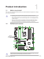
Chapter 1 Product introduction
1.1 Before you proceed ...................................................................................... 1-1
1.2 Motherboard overview ................................................................................. 1-1
1.3 Central Processing Unit (CPU) .................................................................... 1-7
1.4 System memory ............................................................................................ 1-8
Chapter 2 BIOS and RAID Support
2.1 Knowing BIOS ............................................................................................... 2-1
2.2 BIOS setup program ..................................................................................... 2-2
2.3 ASUS EZ Flash 3 ........................................................................................... 2-3
2.4 ASUS CrashFree BIOS 3 .............................................................................. 2-4
2.5 RAID congurations ..................................................................................... 2-5
Appendix
Notices ..................................................................................................................... A-1
ASUS contact information ...................................................................................... A-6

iv
Safety information
Electrical safety
• To prevent electrical shock hazard, disconnect the power cable from the electrical outlet
before relocating the system.
• When adding or removing devices to or from the system, ensure that the power cables
for the devices are unplugged before the signal cables are connected. If possible,
disconnect all power cables from the existing system before you add a device.
• Before connecting or removing signal cables from the motherboard, ensure that all power
cables are unplugged.
• Seek professional assistance before using an adapter or extension cord. These devices
could interrupt the grounding circuit.
• Ensure that your power supply is set to the correct voltage in your area. If you are not
sure about the voltage of the electrical outlet you are using, contact your local power
company.
• If the power supply is broken, do not try to x it by yourself. Contact a qualied service
technician or your retailer.
Operation safety
• Before installing the motherboard and adding components, carefully read all the manuals
that came with the package.
• Before using the product, ensure all cables are correctly connected and the power cables
are not damaged. If you detect any damage, contact your dealer immediately.
• To avoid short circuits, keep paper clips, screws, and staples away from connectors,
slots, sockets and circuitry.
• Avoid dust, humidity, and temperature extremes. Do not place the product in any area
where it may be exposed to moisture.
• Place the product on a stable surface.
• If you encounter technical problems with the product, contact a qualied service
technician or your retailer.
• Your motherboard should only be used in environments with ambient temperatures
between 0°C and 40°C.

v
About this guide
This user guide contains the information you need when installing and conguring the
motherboard.
How this guide is organized
This guide contains the following parts:
• Chapter 1: Product introduction
This chapter describes the features of the motherboard and the new technology it
supports. It includes descriptions of the switches, jumpers, and connectors on the
motherboard.
• Chapter 2: BIOS and RAID Support
This chapter tells how to boot into the BIOS, upgrade BIOS using the EZ Flash Utility
and support on RAID.
Where to nd more information
Refer to the following sources for additional information and for product and software
updates.
1. ASUS website
The ASUS website provides updated information on ASUS hardware and software
products. Refer to the ASUS contact information.
2. Optional documentation
Your product package may include optional documentation, such as warranty yers,
that may have been added by your dealer. These documents are not part of the
standard package.
Conventions used in this guide
To ensure that you perform certain tasks properly, take note of the following symbols used
throughout this manual.
CAUTION: Information to prevent damage to the components and injuries to
yourself when trying to complete a task.
IMPORTANT: Instructions that you MUST follow to complete a task.
NOTE: Tips and additional information to help you complete a task.

vi
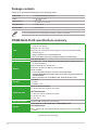
CPU
Intel® Socket LGA1200 for 10th Gen Intel® Core™, Pentium® Gold and
Celeron® Processors*
Supports Intel® 14nm CPU
Supports Intel® Turbo Boost Technology 2.0 and Intel® Turbo Boost Max
Technology 3.0**
* Refer to www.asus.com for CPU support list.
** Intel® Turbo Boost Technology 3.0 support depends on the CPU types.
Chipset Intel® B460 Chipset
Memory
4 x DIMM, Max. 128GB, DDR4 2933/2800/2666/2400/2133 MHz Non-ECC,
Un-buffered Memory*
Dual Channel Memory Architecture
Supports Intel® Extreme Memory Prole (XMP)
ASUS OptiMem
* For 10th Gen Intel® processors, only Core™ i9/i7 CPUs support
2933/2800/2666/2400/2133 natively, others will run at the maximum transfer rate
of DDR4 2666MHz.
** Refer to www.asus.com for the Memory QVL (Qualied Vendors Lists).
Graphics
1 x D-Sub
1 x DVI-D
1 x HDMITM 1.4b
Expansion Slots
Intel® 10th Gen Processors
1 x PCIe 3.0x16 slot (supports x16 mode)
Intel® B460 Chipset
1 x PCIe 3.0 x16 slot (supports x4 mode)
2 x PCIe 3.0 x1 slots
2 x PCI slots
Multi-GPU Support Supports AMD CrossFireX™ Technology
Storage
Total supports 2 x M.2 slots and 6 x SATA 6Gb/s ports
Intel® B460 Chipset
M.2_1 slot (Key M), type 2242/2260/2280 (supports PCIe 3.0 x4 & SATA
modes)*
(continued on the next page)
Package contents
Check your motherboard package for the following items.
Motherboard 1 x PRIME B460-PLUS motherboard
Cables 2 x SATA 6Gb/s cables
Miscellaneous 1 x I/O Shield
1 x M.2 SSD screw package
Application DVD 1 x Support DVD
Documentation 1 x User manual
If any of the above items is damaged or missing, contact your retailer.
PRIME B460-PLUS specications summary

vii
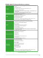
PRIME B460-PLUS specications summary
Storage
M.2_2 slot (Key M), type 2242/2260/2280/22110 (supports PCIe 3.0 x4
mode)
6 x SATA 6Gb/s ports
Intel® Rapid Storage Technology supports Raid 0,1,5,10
Intel® Optane™ Memory Ready**
* When a device in SATA mode is installed on the M.2_1 socket, SATA6G_1 port
cannot be used.
** Only the M.2_2 socket can support Intel® Optane™ memory.
Ethernet 1 x Realtek RTL8111H 1Gb Ethernet
USB
Rear USB (Total 6 ports)
4 x USB 3.2 Gen 1 ports (4 x Type-A)
2 x USB 2.0 ports (2 x Type-A)
Front USB (Total 6 ports)
1 x USB 3.2 Gen 1 header supports additional 2 USB 3.2 Gen 1 ports
2 x USB 2.0 headers support additional 4 USB 2.0 ports
Audio
Realtek ALC887 7.1-Channel High Denition Audio CODEC*
- Jack-detection, Multi-streaming, Front Panel Jack-retasking
- Supports up to 24-Bit/192kHz playback
Audio Features
- LED-illuminated audio trace path design
- Premium Japanese audio capacitors
- Audio Shielding
- Dedicated audio PCB layers
* A chassis with an HD audio module in the front panel is required to support
7.1-channel audio output.
Back Panel I/O Ports
4 x USB 3.2 Gen 1 ports (4 x Type-A)
2 x USB 2.0 ports (2 x Type-A)
1 x D-Sub port
1 x DVI-D port
1 x HDMITM port
1 x Realtek RTL8111H 1Gb Ethernet port
3 x Audio jacks
1 x PS/2 Keyboard/Mouse combo port
Internal I/O
Connectors
Fan and cooling related
1 x 4-pin CPU Fan header
3 x 4-pin Chassis Fan headers
Power related
1 x 24-pin Main Power connector
1 x 8-pin +12V Power connector
Storage related
2 x M.2 slots (Key M)
6 x SATA 6Gb/s ports
USB
1 x USB 3.2 Gen 1 header supports additional 2 USB 3.2 Gen 1 ports
2 x USB 2.0 headers support additional 4 USB 2.0 ports
(continued on the next page)

viii
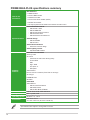
PRIME B460-PLUS specications summary
Internal I/O
Connectors
Miscellaneous
2 x RGB headers
1 x Clear CMOS header
1 x COM Port header
1 x Front Panel Audio header (AAFP)
1 x S/PDIF Out header
1 x 20-3pin System Panel header with Chassis intrude function
Special Features
ASUS 5X PROTECTION III
- ASUS DIGI+ VRM
- ASUS LANGuard
- ASUS Overvoltage Protection
- ASUS SafeSlot Core
- ASUS Stainless-Steel Back I/O
ASUS Q-Design
- ASUS Q-DIMM
- ASUS Q-Slot
ASUS Thermal Solution
- Aluminum heatsink design
ASUS Lighting Control
- Standard RGB headers
Software
Features
ASUS Exclusive Software
Armoury Crate
AI Suite 3
- Performance And Power Saving Utility
TurboV EVO
EPU
Digi+ VRM
Fan Xpert 2+
- EZ update
ASUS CPU-Z
Norton Anti-virus software (Free Trial for 60 days)
AI Charger
DAEMON Tools
WinRAR
UEFI BIOS
ASUS EZ DIY
- ASUS CrashFree BIOS 3
- ASUS EZ Flash 3
- ASUS UEFI BIOS EZ Mode
BIOS 128 Mb Flash ROM, UEFI AMI BIOS
Manageability WOL by PME, PXE
Operating System Windows® 10 - 64 bit
Form Factor ATX Form Factor
12.0 inch x 9.0 inch (30.5 cm x 22.86 cm)
Specications are subject to change without notice.

ix
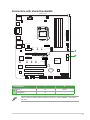
Connectors with shared bandwidth
A
A
PCIEX16_1
PCIEX16_2
PCI_1
PCI_2
PCIEX1_1
PCIEX1_2
ALC
887
M.2_1(SOCKET3)
M.2_1(SOCKET3)
M.2_2(SOCKET3)
RTL
8111H
USB910 USB1112
AAFP
SPDIF_OUT
CLRTC
EATXPWR
BATTERY
Super
I/O
ASM
1083
ASM
1442K
2280 2260 2242
228022110 2260 2242
KBMS_USB78
22.86cm(9.0in)
DDR4 DIMM_B1 (64bit, 288-pin module)
DDR4 DIMM_B2* (64bit, 288-pin module)
DDR4 DIMM_A1 (64bit, 288-pin module)
DDR4 DIMM_A2* (64bit, 288-pin module)
SATA6G_2 SATA6G_1
LAN_U32G1_34
U32G1_56
HDMI
CHA_FAN1
CHA_FAN2
RGB_HEADER2
CPU_FAN
CHA_FAN3
30.5cm(12in)
LGA1200
DIGI
+VRM
COM
EATX12V
U32G1_12
Intel®
B460
128Mb
BIOS
PANEL
AUDIO
SATA6G_5 SATA6G_6
SATA6G_3 SATA6G_4
LANGuard
PCIE SATA IRST
X4 VX
PCIE SATA IRST
X4 V X
DVI
VGA
Conguration 1 2
AM.2_1 x4 SATA
SATA6G_1 V -
When a device in SATA mode is installed on the M.2_1 socket, SATA6G_1 port cannot
be used.

x

ASUS PRIME B460-PLUS 1-1
Product introduction
1
1.1 Before you proceed
Take note of the following precautions before you install motherboard components or change
any motherboard settings.
• Unplugthepowercordfromthewallsocketbeforetouchinganycomponent.
• Beforehandlingcomponents,useagroundedwriststraportouchasafelygrounded
objectorametalobject,suchasthepowersupplycase,toavoiddamagingthemdue
to static electricity.
• Beforeyouinstallorremoveanycomponent,ensurethattheATXpowersupplyis
switched off or the power cord is detached from the power supply. Failure to do so
maycauseseveredamagetothemotherboard,peripherals,orcomponents.
Unplugthepowercordbeforeinstallingorremovingthemotherboard.Failuretodosocan
cause you physical injury and damage motherboard components.
1.2 Motherboard overview
Place this
side towards
the rear of the
chassis
PCIEX16_1
PCIEX16_2
PCI_1
PCI_2
PCIEX1_1
PCIEX1_2
ALC
887
M.2_1(SOCKET3)
M.2_1(SOCKET3)
M.2_2(SOCKET3)
RTL
8111H
USB910 USB1112
AAFP
SPDIF_OUT
CLRTC
EATXPWR
BATTERY
Super
I/O
ASM
1083
ASM
1442K
2280 2260 2242
228022110 2260 2242
KBMS_USB78
22.86cm(9.0in)
DDR4 DIMM_B1 (64bit, 288-pin module)
DDR4 DIMM_B2* (64bit, 288-pin module)
DDR4 DIMM_A1 (64bit, 288-pin module)
DDR4 DIMM_A2* (64bit, 288-pin module)
SATA6G_2 SATA6G_1
LAN_U32G1_34
U32G1_56
HDMI
CHA_FAN1
CHA_FAN2
RGB_HEADER2
CPU_FAN
CHA_FAN3
30.5cm(12in)
LGA1200
DIGI
+VRM
COM
EATX12V
U32G1_12
Intel®
B460
128Mb
BIOS
PANEL
AUDIO
SATA6G_5 SATA6G_6
SATA6G_3 SATA6G_4
LANGuard
PCIE SATA IRST
X4 VX
PCIE SATA IRST
X4 V X
DVI
VGA
5 64 1 24
159410121413
5
4
8
7
11
7
3
6
17
3

1-2 Chapter 1: Product introduction
1.2.1 Layout contents
1. CPU socket
The motherboard comes with a surface mount Intel®SocketLGA1200designedfor10th Gen
Intel® CoreTM,Pentium® Gold and Celeron®Processors.
Formoredetails,refertoCentral Processing Unit (CPU).
2. DDR4 DIMM slots
The motherboard comes with Dual Inline Memory Modules (DIMM) slots designed for DDR4
(Double Data Rate 4) memory modules.
Formoredetails,refertoSystem memory.
3. Expansion slots
ThismotherboardsupportstwoPCIe3.0x16andtwoPCIe3.0x1networkcards,SCSI
cards,andothercardsthatcomplywiththePCIExpressspecications
ThePCIslotssupportcardssuchasLANcards,SCSIcards,USBcards,andothercards
thatcomplywithPCIspecications.
Slot Description Single VGA Dual VGA
PCIe 3.0 x16_1 x16(RecommendedforsingleVGAcard) x16
PCIe 3.0 x16_2 - x4
• InsingleVGAcardmode,usethePCIEX16_1slot(gray)foraPCIex16graphicscard
to get better performance.
• WerecommendthatyouprovidesufcientpowerwhenrunningCrossFireX™mode.
• ConnectachassisfantothemotherboardconnectorlabeledCHA_FAN1/2/3when
usingmultiplegraphicscardsforbetterthermalenvironment.
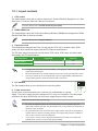
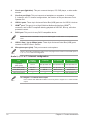
4. Fan headers
The Fan headers allow you to connect fans to cool the system.
5. Power connectors
ThesePowerconnectorsallowyoutoconnectyourmotherboardtoapower
supply.Thepowersupplyplugsaredesignedtotinonlyoneorientation.Findtheproper
orientationandpushdownrmlyuntilthepowersupplyplugsarefullyinserted.
Ensuretoconnectthe8-pinpowerplug.
• Forafullyconguredsystem,werecommendthatyouuseapowersupplyunit
(PSU)thatcomplieswithATX12VSpecication2.0(orlaterversion)andprovidesa
minimumpowerof350W.
• WerecommendthatyouuseaPSUwithahigherpoweroutputwhenconguringa
systemwithmorepower-consumingdevices.Thesystemmaybecomeunstableor
may not boot up if the power is inadequate.
• Ifyouwanttousetwoormorehigh-endPCIExpressx16cards,useaPSUwith
1000Wpowerorabovetoensurethesystemstability.
FAN PWM
FAN IN
FAN PWR
GND

ASUS PRIME B460-PLUS 1-3
6. M.2 Slots (Key M)
TheM.2slotsallowyoutoinstallM.2devicessuchasM.2SSDmodules.
• M.2_1slot(KeyM),type2242/2260/2280(supportsSATA&PCIe3.0x4modes).
• M.2_2slot(KeyM),type2242/2260/2280/22110(supportsPCIe3.0x4mode).
• OnlyM.2_2slotcansupportIntel®Optane™Memory.
• WhenadeviceinSATAmodeisinstalledontheM.2_1slot,SATA6G_1isdisabled.
7. SATA 6Gb/s ports
TheSATA6Gb/sportsallowyoutoconnectSATAdevicessuchasopticaldiscdrivesand
harddiskdrivesviaaSATAcable.
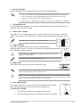
8. USB 3.2 Gen 1 header
TheUSB3.2Gen1headerallowsyoutoconnectaUSB3.2Gen1moduleforadditional
USB3.2Gen1ports.TheUSB3.2Gen1headerprovidesdatatransferspeedsofupto5
Gb/s.
TheUSB3.2Gen1moduleispurchasedseparately.
9. USB 2.0 headers
TheUSB2.0headersallowyoutoconnectaUSBmodulefor
additionalUSB2.0ports.TheUSB2.0headersprovidedatatransferspeedsof
upto480Mb/sconnectionspeed.
DONOTconnecta1394cabletotheUSBconnectors.Doingsowill
damage the motherboard!
TheUSB2.0moduleispurchasedseparately.
10. RGB header
TheRGBheaderallowsyoutoconnectRGBLEDstrips.
TheRGBheadersupports5050RGBmulti-colorLEDstrips(12V/G/R/B),withamaximum
powerratingof3A(12V),andnolongerthan3m.
Beforeyouinstallorremoveanycomponent,ensurethattheATXpowersupplyisswitched
offorthepowercordisdetachedfromthepowersupply.Failuretodosomaycausesevere
damagetothemotherboard,peripherals,orcomponents.
11. Clear CMOS header
ThisheaderallowsyoutocleartheCMOSRTCRAMdataofthesystem
setupinformationsuchasdate,time,andsystempasswords.
To erase the RTC RAM:
1. TurnOFFthecomputerandunplugthepowercord.
2. Useametalobjectsuchasascrewdrivertoshortthetwopins.
USB3+5V
IntA_P1_SSRX-
IntA_P1_SSRX+
GND
IntA_P1_SSTX-
IntA_P1_SSTX+
GND
IntA_P1_D-
IntA_P1_D+
GND
PIN 1
USB3+5V
IntA_P2_SSRX-
IntA_P2_SSRX+
GND
IntA_P2_SSTX-
IntA_P2_SSTX+
GND
IntA_P2_D-
IntA_P2_D+
CLRTC
+3V_BAT
GND
PIN 1
USB+5V
USB_P11-
USB_P11+
GND
NC
USB+5V
USB_P12-
USB_P12+
GND
PIN 1

1-4 Chapter 1: Product introduction
3. PlugthepowercordandturnONthecomputer.
4. Holddownthe<Del>keyduringthebootprocessandenterBIOSsetuptore-
enter data.
Ifthestepsabovedonothelp,removetheonboardbatteryandshortthetwopinsagainto
cleartheCMOSRTCRAMdata.AfterclearingtheCMOS,reinstallthebattery.
12. COM Port header
Thisheaderisforaserial(COM)port.Connecttheserialportmodulecable
tothisheader,theninstallthemoduletoaslotopeningatthebackofthe
system chassis.
13. Front panel audio header
Thisheaderisforachassis-mountedfrontpanelaudioI/Omodulethat
supportsHDaudiostandard.Connectoneendofthefrontpanelaudio
I/Omodulecabletothisheader.
• Werecommendthatyouconnectahigh-denitionfrontpanel
audiomoduletothisheadertoavailofthemotherboard’shigh-
denitionaudiocapability.
• Ifyouwanttoconnectahigh-denitionfrontpanelaudio
moduletothisheader,settheFrontPanelTypeiteminthe
BIOSsetupto[HDAudio].Bydefault,thisheaderissetto[HD
Audio].
14. S/PDIF Out header
ThisheaderisforanadditionalSony/PhilipsDigitalInterface(S/PDIF)port.
ConnecttheS/PDIFOutmodulecabletothisheader,theninstallthemoduleto
a slot opening at the back of the system chassis.
15. 20-3 pin System Panel header
Thisheadersupportsseveralchassis-mountedfunctions.
• SystempowerLED(2-pin+PWR_LED-)
This2-pinheaderisforthesystempowerLED.Connectthe
chassispowerLEDcabletothisheader.Thesystempower
LEDlightsupwhenyouturnonthesystempower,andblinks
when the system is in sleep mode.
• HarddiskdriveactivityLED(2-pin+HDD_LED-)
This2-pinheaderisfortheHDDActivityLED.Connectthe
HDDActivityLEDcabletothisheader.TheHDDLEDlightsup
orasheswhendataisreadfromorwrittentotheHDD.
• Systemwarningspeaker(4-pinSPEAKER)
This 4-pin header is for the chassis-mounted system warning speaker. The speaker
allows you to hear system beeps and warnings.
PLED+
PLED-
PWR
Ground
+5V
Ground
Ground
Speaker
CASEOPEN
HDD_LED+
HDD_LED-
GND
Reset
+5V
PLED+
PLED-
GND
PIN 1
+PWR_LED-
+PWR_LED-
SPEAKER
PANEL
+HDD_LED-
PWR_SW
RESET
* Requires an ATX power supply
CHASSIS
AAFP
AGND
NC
SENSE1_RETUR
SENSE2_RETUR
PORT1 L
PORT1 R
PORT2 R
SENSE_SEND
PORT2 L
HD-audio-compliant
pin definition
SPDIF_OUT
+5V
SPDIFOUT
GND
PIN 1
COM
DCD
TXD
GND
RTS
RI
RXD
DTR
DSR
CTS

ASUS PRIME B460-PLUS 1-5
• ATXpowerbutton/soft-offbutton(2-pinPWR_SW)
Thisheaderisforthesystempowerbutton.Pressingthepowerbuttonturnsthe
system on or puts the system in sleep or soft-off mode depending on the operating
systemsettings.Pressingthepowerswitchformorethanfoursecondswhilethe
systemisONturnsthesystemOFF.
• Resetbutton(2-pinRESET)
This 2-pin header is for the chassis-mounted reset button for system reboot without
turning off the system power.
• Chassisintrusionheader(2-pinCHASSIS)
This header is for a chassis-mounted intrusion detection sensor or switch. Connect one
end of the chassis intrusion sensor or switch cable to this header. The chassis intrusion
sensororswitchsendsahigh-levelsignaltothisconnectorwhenachassiscomponent
isremovedorreplaced.Thesignalisthengeneratedasachassisintrusionevent.
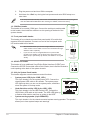
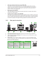
1.2.2 Rear panel connectors
1 2
6 8 97 10
3 4 5
1. PS/2 keyboard/mouse combo port.ThisportisforaPS/2mouseorkeyboard.
2. Video Graphics Adapter (VGA) port.This15-pinportisforaVGAmonitororother
VGA-compatibledevices.
3. Ethernet port.ThisportallowsGigabitconnectiontoaLocalAreaNetwork(LAN)
throughanetworkhub.RefertothetablebelowfortheEthernetportLEDindications.
Ethernet port
Speed
LED
Activity Link
LED
Activity/Link LED Speed LED
Status Description Status Description
Off Nolink OFF 10Mbpsconnection
Orange Linked ORANGE 100Mbpsconnection
Orange(Blinking) Dataactivity GREEN 1Gbps connection
Orange(Blinking
then steady)
Ready to wake
upfromS5mode
Ethernet port LED indications

1-6 Chapter 1: Product introduction
4. Line In port (light blue).Thisportconnectsthetape,CD,DVDplayer,orotheraudio
sources.
5. Line Out port (lime).Thisportconnectsaheadphoneoraspeaker.In4-channel,
5.1-channel,and7.1-channelcongurations,thefunctionofthisportbecomesFront
SpeakerOut.
6. USB 2.0 ports.These4-pinUniversalSerialBus(USB)portsareforUSB2.0devices.
7. HDMITM port.ThisportisforaHigh-DenitionMultimediaInterface(HDMITM)
connector,andisHDCPcompliantallowingplaybackofHDDVD,Blu-ray,andother
protected content.
8. DVI-D port.ThisportisforanyDVI-Dcompatibledevice.
DVI-DcannotbeconvertedtooutputfromRGBSignaltoCRTandisnotcompatiblewith
DVI-I.
9. USB 3.2 Gen 1 (up to 5Gbps) ports.These9-pinUniversalSerialBus(USB)ports
connecttoUSB3.2Gen1devices.
10. Microphone port (pink). This port connects a microphone.
Refertotheaudiocongurationtableonthenextpageforthefunctionoftheaudioportsin
2,4,5.1,or7.1-channelconguration.
Audio2,4,5.1or7.1-channelconguration
Port Headset
2-channel 4-channel 5.1-channel 7.1-channel
LightBlue
(Rear panel) Line In RearSpeakerOut RearSpeakerOut RearSpeakerOut
Lime (Rear panel) LineOut FrontSpeakerOut FrontSpeakerOut FrontSpeakerOut
Pink(Rearpanel) Mic In Mic In Bass/Center Bass/Center
Lime (Front panel) — — — SideSpeakerOut
Tocongurea7.1-channelaudiooutput:
UseachassiswithHDaudiomoduleinthefrontpaneltosupporta7.1-channelaudio
output.

ASUS PRIME B460-PLUS 1-7
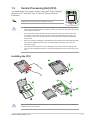
1.3 Central Processing Unit (CPU)
This motherboard comes with a surface mount Intel® SocketLGA1200
designedfor10th Gen Intel®Core™,Pentium® Gold and Celeron®
Processors.
UnplugallpowercablesbeforeinstallingtheCPU.
• EnsurethatyouinstallthecorrectCPUdesignedfortheLGA1200socketonly.DO
NOTinstallaCPUdesignedforLGA1150,LGA1151,LGA1155andLGA1156sockets
ontheLGA1200socket.
• Uponpurchaseofthemotherboard,ensurethatthePnPcapisonthesocketand
thesocketcontactsarenotbent.ContactyourretailerimmediatelyifthePnPcap
ismissing,orifyouseeanydamagetothePnPcap/socketcontacts/motherboard
components.
• Keepthecapafterinstallingthemotherboard.ASUSwillprocessReturnMerchandise
Authorization(RMA)requestsonlyifthemotherboardcomeswiththecaponthe
LGA1200socket.
• Theproductwarrantydoesnotcoverdamagetothesocketcontactsresultingfrom
incorrectCPUinstallation/removal,ormisplacement/loss/incorrectremovalofthePnP
cap.
Installing the CPU
1
4
ApplytheThermalInterfaceMaterialtotheCPUheatsinkandCPUbeforeyouinstallthe
heatsink and fan if necessary.
2
3
A
B
A
B
C
D
5
4
4
5

1-8 Chapter 1: Product introduction
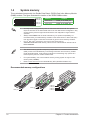
1.4 System memory
This motherboard comes with four Double Data Rate 4 (DDR4) Dual Inline Memory Module
(DIMM)sockets.ThegureillustratesthelocationoftheDDR4DIMMsockets:
Channel Sockets
ChannelA DIMM_A1&DIMM_A2*
ChannelB DIMM_B1&DIMM_B2*
DIMM_B1
DIMM_B2*
DIMM_A1
DIMM_A2*
• YoumayinstallvaryingmemorysizesinChannelAandChannelB.Thesystem
mapsthetotalsizeofthelower-sizedchannelforthedual-channelconguration.Any
excessmemoryfromthehigher-sizedchannelisthenmappedforsingle-channel
operation.
• AlwaysinstallDIMMswiththesameCASlatency.Foroptimalcompatibility,we
recommendthatyouinstallmemorymodulesofthesameversionordatecode(D/C)
fromthesamevendor.Checkwiththeretailertogetthecorrectmemorymodules.
• For10th Gen Intel®processors,onlyCore™i9/i7CPUssupport
2933/2800/2666/2400/2133natively,otherswillrunatthemaximumtransferrateof
DDR42666MHz.
• ThedefaultmemoryoperationfrequencyisdependentonitsSerialPresenceDetect
(SPD),whichisthestandardwayofaccessinginformationfromamemorymodule.
Underthedefaultstate,somememorymodulesforoverclockingmayoperateata
lowerfrequencythanthevendor-markedvalue.
• Forsystemstability,useamoreefcientmemorycoolingsystemtosupportafull
memory load (4 DIMMs).
• Refertowww.asus.comforthelatestMemoryQVL(QualiedVendorsList).
Recommendedmemorycongurations
DIMM_A2*
DIMM_B1
DIMM_B2*
DIMM_A2*
DIMM_B2*
DIMM_A1
DIMM_A2*

ASUS PRIME B460-PLUS 1-9
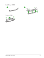
Installing a DIMM
1 2
B
A
A
To remove a DIMM
B
A

1-10 Chapter 1: Product introduction
Pagina se încarcă...
Pagina se încarcă...
Pagina se încarcă...
Pagina se încarcă...
Pagina se încarcă...
Pagina se încarcă...
Pagina se încarcă...
Pagina se încarcă...
Pagina se încarcă...
Pagina se încarcă...
Pagina se încarcă...
Pagina se încarcă...
-
 1
1
-
 2
2
-
 3
3
-
 4
4
-
 5
5
-
 6
6
-
 7
7
-
 8
8
-
 9
9
-
 10
10
-
 11
11
-
 12
12
-
 13
13
-
 14
14
-
 15
15
-
 16
16
-
 17
17
-
 18
18
-
 19
19
-
 20
20
-
 21
21
-
 22
22
-
 23
23
-
 24
24
-
 25
25
-
 26
26
-
 27
27
-
 28
28
-
 29
29
-
 30
30
-
 31
31
-
 32
32


Asus PRIME B460-PLUS Motherboard Manual de utilizare
- Categorie
- Plăci de bază
- Tip
- Manual de utilizare
în alte limbi
Lucrări înrudite
-
Asus TUF GAMING B760M-E D4 Manual de utilizare
-
-
-
-
-
-
-
-
-